| [version en cours de rédaction] | [version en cours de rédaction] |
| Ligne 38 : | Ligne 38 : | ||
All bolts to be pen marked once adhesive applied and correct tension added</translate> | All bolts to be pen marked once adhesive applied and correct tension added</translate> | ||
|Step_Picture_00=R0015086_Assemble_Pneumatics_on_to_electrical_cabinet_loctite_243.png | |Step_Picture_00=R0015086_Assemble_Pneumatics_on_to_electrical_cabinet_loctite_243.png | ||
| + | }} | ||
| + | {{Tuto Step | ||
| + | |Step_Title=<translate>Ensure mains air is connected to module</translate> | ||
| + | |Step_Content=<translate>Connect mains air to module to allow setting of roller beds</translate> | ||
| + | }} | ||
| + | {{Tuto Step | ||
| + | |Step_Title=<translate>Adjust Level</translate> | ||
| + | |Step_Content=<translate>Using the cylinder stroke, Roller bed assemblies will need to be adjusted to a level position | ||
| + | |||
| + | |||
| + | 1 Place engineers level above support bracket as shown | ||
| + | |||
| + | |||
| + | 2 Wind back cylinder lock nut and apply Loctite 243 to thread of cylinder | ||
| + | |||
| + | |||
| + | 3 Adjust cylinder stroke to achieve level | ||
| + | |||
| + | |||
| + | 4 Lock off cylinder nut and confirm level has been maintained , if not adjust and tension lock nut. | ||
| + | |||
| + | |||
| + | 5 (Skip to step 6 if a single bracket roller assembly ) | ||
| + | |||
| + | Repeat on Second Bracket attached to assembly . Previous bracket setting must be checked after adjusting second bracket. Confirm both are level | ||
| + | |||
| + | |||
| + | 5 Mark Lock nut as complete when final setting is complete and locked off</translate> | ||
| + | |Step_Picture_00=R0015267_Assemble_Backfences__Fit_and_Align_Screenshot_2023-09-07_150927.png | ||
| + | |Step_Picture_01=R0015267_Assemble_Backfences__Fit_and_Align_Screenshot_2023-09-07_150952.png | ||
| + | |Step_Picture_02=R0015267_Assemble_Backfences__Fit_and_Align_Screenshot_2023-09-07_151012.png | ||
| + | }} | ||
| + | {{Tuto Step | ||
| + | |Step_Title=<translate>Adjust and Set Height</translate> | ||
| + | |Step_Content=<translate>1 Remove m8 Socket Caps individually on each roller bed as it is being adjusted for height and apply Loctite 243 | ||
| + | |||
| + | |||
| + | 2 Place 2 off 2mm shims on top of green runner strips as indicated | ||
| + | |||
| + | |||
| + | 3 Span across these with 2 meter straight edge | ||
| + | |||
| + | |||
| + | 4 Lift roller assembly up to align with bottom face of straight edge | ||
| + | |||
| + | |||
| + | 5 Tighten and finalise M8 Fixing bolts</translate> | ||
| + | |Step_Picture_00=R0015267_Assemble_Backfences__Fit_and_Align_Screenshot_2023-09-07_151054.png | ||
| + | |Step_Picture_01=R0015267_Assemble_Backfences__Fit_and_Align_Screenshot_2023-09-07_151102.png | ||
| + | |Step_Picture_02=R0015267_Assemble_Backfences__Fit_and_Align_Screenshot_2023-09-07_151108.png | ||
| + | |Step_Picture_03=R0015267_Assemble_Backfences__Fit_and_Align_Screenshot_2023-09-07_151115.png | ||
| + | }} | ||
| + | {{Tuto Step | ||
| + | |Step_Title=<translate>Repeat</translate> | ||
| + | |Step_Content=<translate>Repeat step 5 for all other roller bed assemblies except R0015081 using the same method | ||
| + | |||
| + | |||
| + | To level R0015081 place shims at points indicated and extend straight edge over to allow height setting</translate> | ||
| + | |Step_Picture_00=R0015267_Assemble_Backfences__Fit_and_Align_Screenshot_2023-09-07_151212.png | ||
| + | |Step_Picture_01=R0015267_Assemble_Backfences__Fit_and_Align_Screenshot_2023-09-07_151219.png | ||
| + | }} | ||
| + | {{Tuto Step | ||
| + | |Step_Title=<translate>Quality Check</translate> | ||
| + | |Step_Content=<translate>Once all roller beds have been mounted and aligned , use the 2 meter straight edge to travel across the entire length of the finalised roller beds | ||
| + | |||
| + | |||
| + | Transition should be smooth between roller bed assemblies, with no bumps or drops onto roller beds from previous ones</translate> | ||
| + | |Step_Picture_00=R0000711_Rotary_Base_Assembly_quality-assurance-testing.png | ||
}} | }} | ||
{{Tuto Step | {{Tuto Step | ||
Version du 7 septembre 2023 à 16:13
Alignment requirements and details for Backfence

Difficulté
Moyen
Durée
2 heure(s)
Sommaire
- 1 Introduction
- 2 Étape 1 - unless otherwise stated
- 3 Étape 2 - Ensure mains air is connected to module
- 4 Étape 3 - Adjust Level
- 5 Étape 4 - Adjust and Set Height
- 6 Étape 5 - Repeat
- 7 Étape 6 - Quality Check
- 8 Étape 7 - Assemble backfences
- 9 Étape 8 - Mount backfences to frame
- 10 Étape 9 - Retract middle positions of backfences
- 11 Étape 10 - Wire line setting
- 12 Commentaires
Introduction
Tools Required
Standard Hex Key set
Wire Line
150mm Rule
Parts Required
D0015420 M/C Infeed Backfence Plate x 9
D0015468 Infeed Backfence Bracket x 9
Étape 1 - unless otherwise stated
All bolts to have Loctite 243 adhesive applied unless otherwise stated
All Threaded Pneumatic connections to have Loctite 570 applied
All bolts to be pen marked once adhesive applied and correct tension added

Étape 2 - Ensure mains air is connected to module
Connect mains air to module to allow setting of roller beds
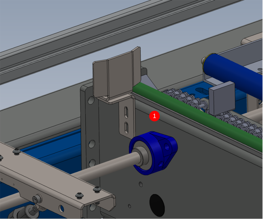
Étape 3 - Adjust Level
Using the cylinder stroke, Roller bed assemblies will need to be adjusted to a level position
1 Place engineers level above support bracket as shown
2 Wind back cylinder lock nut and apply Loctite 243 to thread of cylinder
3 Adjust cylinder stroke to achieve level
4 Lock off cylinder nut and confirm level has been maintained , if not adjust and tension lock nut.
5 (Skip to step 6 if a single bracket roller assembly )
Repeat on Second Bracket attached to assembly . Previous bracket setting must be checked after adjusting second bracket. Confirm both are level
5 Mark Lock nut as complete when final setting is complete and locked off


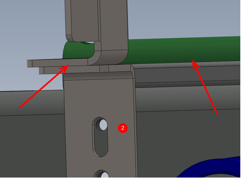
Étape 4 - Adjust and Set Height
1 Remove m8 Socket Caps individually on each roller bed as it is being adjusted for height and apply Loctite 243
2 Place 2 off 2mm shims on top of green runner strips as indicated
3 Span across these with 2 meter straight edge
4 Lift roller assembly up to align with bottom face of straight edge
5 Tighten and finalise M8 Fixing bolts


Étape 5 - Repeat
Repeat step 5 for all other roller bed assemblies except R0015081 using the same method
To level R0015081 place shims at points indicated and extend straight edge over to allow height setting


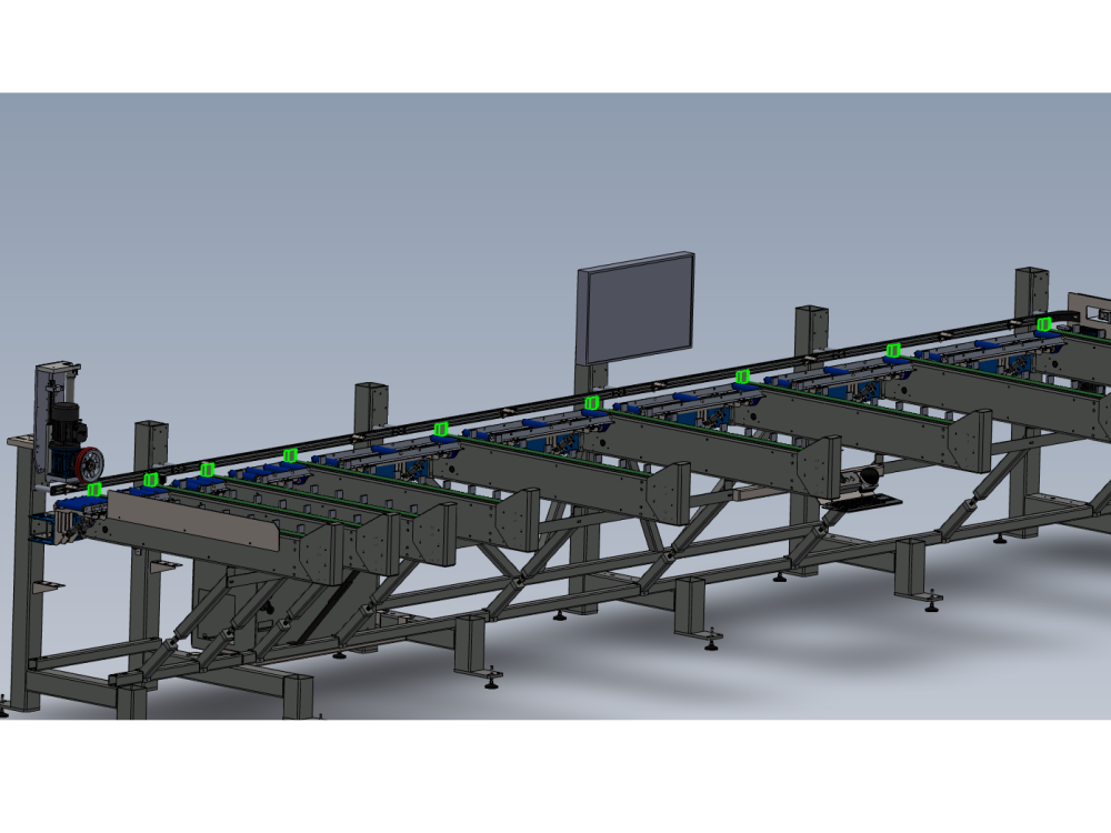
Étape 6 - Quality Check
Once all roller beds have been mounted and aligned , use the 2 meter straight edge to travel across the entire length of the finalised roller beds
Transition should be smooth between roller bed assemblies, with no bumps or drops onto roller beds from previous ones

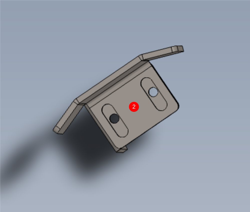
Étape 7 - Assemble backfences
1 Mount D0015420 M/C Infeed Backfence Plate to D0015468 Infeed Backfence Bracket as shown
2 position at middle slot as shown
Use 2 off M6 x 12 Socket cap and A form washers to fix parts together
Do not add adhesive at this stage

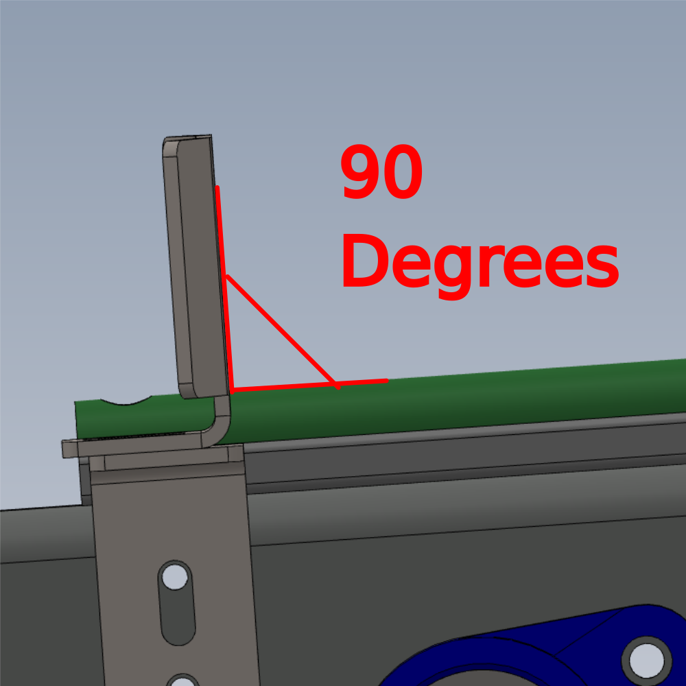
Étape 8 - Mount backfences to frame
1 Mount assembled backfences to frame in position shown on each loader arm
(parts removed for clarity )
Use M6 x 16 Socket caps with m6 penny washers to fix
2 Set height to be as shown
3 Ensure back fence is vertical and at 90 degrees to green runner strip
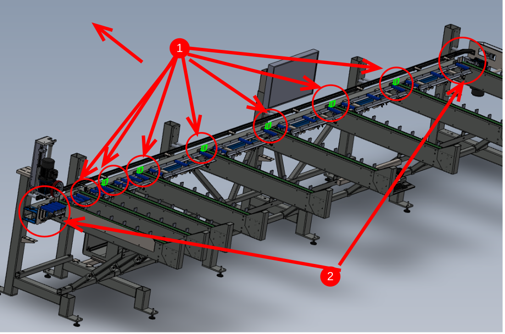
Étape 9 - Retract middle positions of backfences
1 retract indicated backfences in the direction shown to maxuimum movement in slot
2 Check positions shown are middle slot
Étape 10 - Wire line setting
Use dokit Alignment guide using wire line for correct process
Set wire line between 1st and last backfence and adjust middle 7 to correct position
Once aligned , add adhesive to all bolts one at a time
Check that no movement occurs when finalising fixings
Draft
 Français
 English
 Deutsch
 Español
 Italiano
 Português