| [version en cours de rédaction] | [version en cours de rédaction] |
| Ligne 132 : | Ligne 132 : | ||
{{Tuto Step | {{Tuto Step | ||
|Step_Title=<translate>See also</translate> | |Step_Title=<translate>See also</translate> | ||
| − | |Step_Content=<translate>[[Safe Strop Positions - Autoflow Mk4 1]]</translate> | + | |Step_Content=<translate>[[Safe Strop Positions - Autoflow Mk4 1]] |
| + | |||
| + | [[Safe Moving of Top Heavy Machine Modules]]</translate> | ||
}} | }} | ||
{{Notes}} | {{Notes}} | ||
Version actuelle datée du 31 mars 2025 à 14:18
How to safely decommission and load a Stuga Autoflow Mk4.1 machine
Sommaire
- 1 Introduction
- 2 Étape 1 - Move axes to park positions
- 3 Étape 2 - Power off
- 4 Étape 3 - Infeed Conveyor Module - Disconnect
- 5 Étape 4 - Infeed Conveyor Module - Move
- 6 Étape 5 - Infeed Gripper Module - Disconnect
- 7 Étape 6 - Infeed Gripper Module - Stowing
- 8 Étape 7 - Infeed Gripper Module - Attach lifting Equipment
- 9 Étape 8 - Outfeed table disconnect
- 10 Étape 9 - Machining Head and Saw - Disconnects
- 11 Étape 10 - Unlink Upper Guards
- 12 Étape 11 - Split Machining Head and Saw
- 13 Étape 12 - Complete the split
- 14 Étape 13 - See also
- 15 Commentaires
Introduction
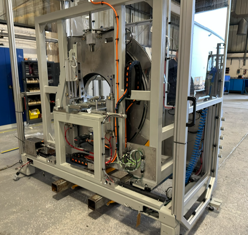
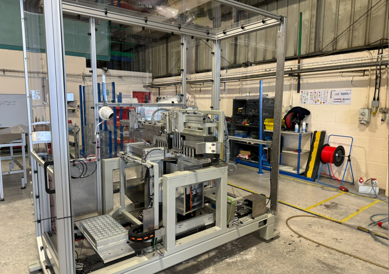
The Autoflow Mk4.1 machine has been designed to separate into modules for safe transport
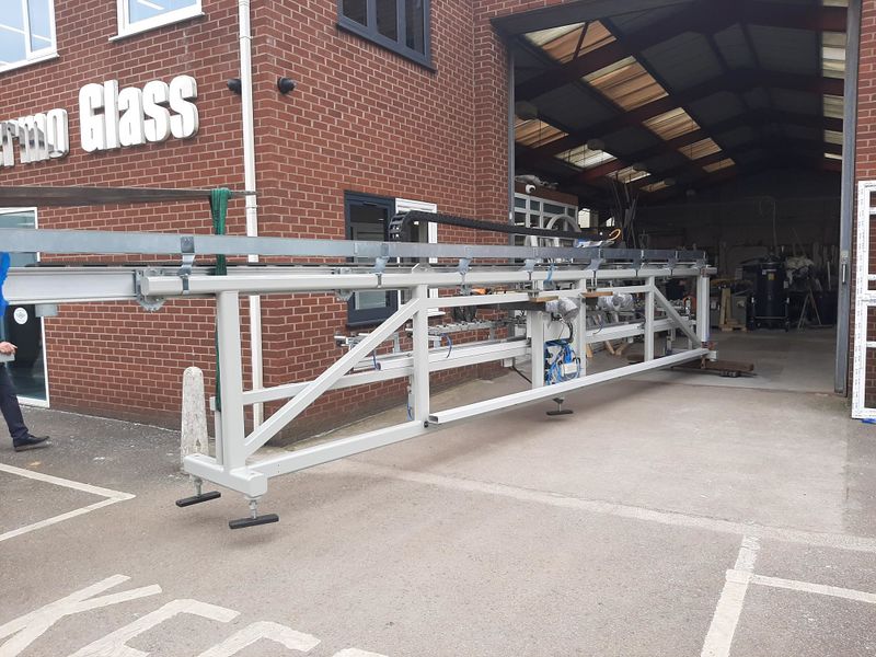
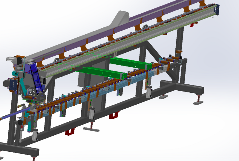
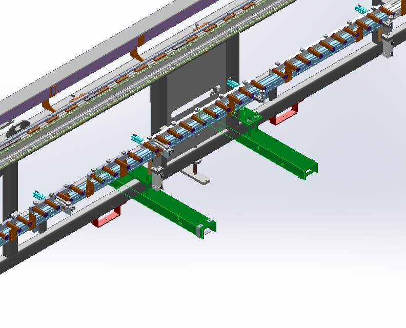
The infeed table gripper carriage and conveyor split into two sections
The machining head and saw split apart like a cam shell. They are joined with a dowel system in joining blocks at the base
The outfeed splits in to a rear bed and front tray
See Also
Étape 1 - Move axes to park positions
- X axis to machining side of lifting points
- Z axis to bottom of travel
- GZ axis to minimum
Étape 2 - Power off
Étape 3 - Infeed Conveyor Module - Disconnect
Ensure the plugs are labelled
Étape 4 - Infeed Conveyor Module - Move
Pull away from backfence towards front of machine
Étape 5 - Infeed Gripper Module - Disconnect
Ensure the plugs are labelled
Étape 6 - Infeed Gripper Module - Stowing
Tie gripper carriage to prevent axis movement in transit
Étape 7 - Infeed Gripper Module - Attach lifting Equipment
Attach safe moving equipment - see R0019264 Autoflow Mk 4,1 Infeed Safe moving equipment
Étape 8 - Outfeed table disconnect
Ensure the plugs are labelled
Étape 9 - Machining Head and Saw - Disconnects
Locate and unplug the electrical and pneumatic interconnections.
Ensure the plugs are labelled
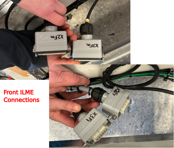
Front Side
- X2F and X3F ILME Connectors. Pull one through one way, one through other way
- Grease Lines - 2 off
- Air Lines Red and Blue
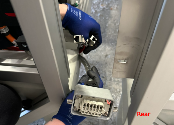
Rear
- ILME Connection
- Network Connection - 2 Off
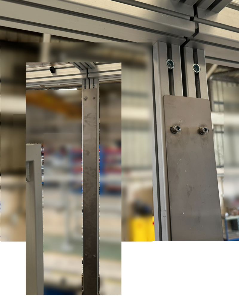
Étape 10 - Unlink Upper Guards
The guard shells are fastened with a plate internally.
Unbolt the Saw side front and rear, then bag and label the screws
Étape 11 - Split Machining Head and Saw
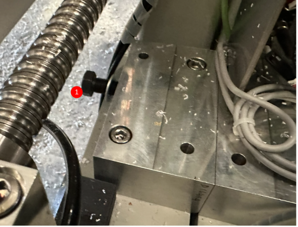
- Remove the M16 front and rear hex head joining bolts, access from saw module. These are the only 2 bolts that fasten the machine together.
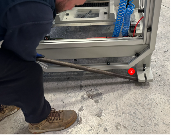
2. Using a crowbar, spit the main modules apart by around 100mm
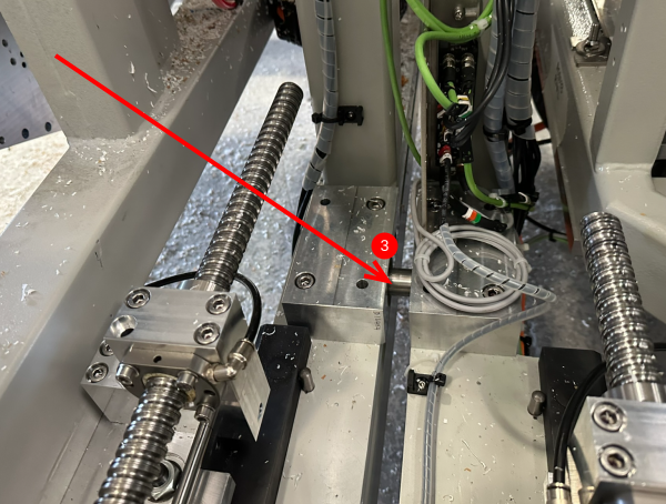
Walk the front and rear by 23-30mm a time until the dowels are clear
3. You will see the location pin exposed in the joining blocks
Draft
 Français
 English
 Deutsch
 Español
 Italiano
 Português