| [version en cours de rédaction] | [version en cours de rédaction] |
m (Stuga Engineer a déplacé la page Fault Finding and Diagnostics Master vers Safety Circuit Fault Finding and Diagnostics Master) |
m (Stuga Engineer a déplacé la page Safety Circuit Fault Finding and Diagnostics Master vers Safety Circuit Principles) |
(Aucune différence)
| |
Version du 29 janvier 2025 à 15:40
A guide on how to fault find an emergency stop circuit fault on any Stuga machine.


Difficulté
Difficile
Durée
60 minute(s)
Sommaire
- 1 Introduction
- 2 Étape 1 - Purpose of the Safety Circuit
- 3 Étape 2 - Different Types of Safety Circuits
- 4 Étape 3 - Identifying Different Circuits
- 5 Étape 4 - Principles of a 'Loop/ Channel'
- 6 Étape 5 - Safety Status and IO
- 7 Étape 6 - Relay Feedback Loop (Restart Circuit)
- 8 Étape 7 - TwinSAFE System
- 9 Étape 8 - Safety Devices and Wiring
- 10 Étape 9 - Other Safety Devices
- 11 Étape 10 - How to Find a Fault with a Safety Circuit (Generic)
- 12 Étape 11 - Machine Specific Information
- 13 Commentaires
Introduction
This tutorial will layout fundmental principles on how to identify issues with an emergency stop circuit and how to use them on any Stuga machine. This will be an ongoing document which can be enhanced by different experiences and evidence of success and failure. Please feel free to add information to help yourself and your colleagues moving forward...
Attention
Pour l'entretien, débranchez l'appareil du secteur
Haute Tension
Étape 1 - Purpose of the Safety Circuit
A machinery safety circuit is designed to protect both the equipment and operators from harm by ensuring safe operation. It monitors critical safety functions, like emergency stops, protective guards, and sensors, to prevent accidents or malfunctions. In case of a failure or hazard detection, the circuit triggers shutdowns or alerts, ensuring that the machine operates within safe limits and reduces the risk of injury or damage.
Étape 2 - Different Types of Safety Circuits
Safety Relay Controllers: These are used to monitor safety devices like emergency stops, interlocks, and door switches. They ensure that the machine stops or enters a safe state when a fault or hazardous condition is detected. This is a hard-wired system using either a single or double channel loop and can have a feedback loop hard-wired into the system with a manual restart button. This system is the most commonly used in the Stuga machinery range.
Safety PLCs (Programmable Logic Controllers): These are specialised PLCs designed to handle safety applications. They provide high levels of safety and redundancy and can integrate both standard control tasks and safety control tasks in the same system, making them suitable for large, complex machinery. We have a number of machines that use a programmable safety system which is know as 'TwinSAFE' and is built into the Beckhoff EtherCAT system. These can be identified in the IO blocks of machine cabinets and have a yellow finish.
Other: There are lots of different types of safety circuit controllers that can be find on different machines. Some of these controllers are very basic and others are very complex.
Étape 3 - Identifying Different Circuits
Picture 1: This is a safety IO slice and is part of the Beckhoff TwinSAFE system.
Picture 2: This is a safety relay which was used on Flowlines and Early ZX machines. This relay can be found in the Saw Infeed (Transfer) cabinet. This relay is typically wired as a single channel loop.
Picture 3: This is a safety relay which was used on Standalone Saws. This relay can be found in the main console electrical cabinet. This relay can vary in colour and some examples of this are blue and yellow. Again, this relay was typically used for a single channel loop. **PICTURES REQUIRED**
Picture 4: This is a safety relay which was introduced on Autoflow 2 machines and then used on ZX5's. This relay can typically be found in the Infeed cabinet on either machine. It is yellow in appearance which makes it prominent inside the cabinet. This relay is used for dual channel loops. **PICTURE REQUIRED**
Picture 5: This is a safety relay which was introduced on later ZX5 machines and now used in all applications from new builds to refurbs. This relay can typically be found in the Infeed cabinet. It is yellow in appearance which makes it prominent inside the cabinet. This relay is used for dual channel loops and provides additional diagnostics and settings on the unit front. **PICTURE REQUIRED**

Étape 4 - Principles of a 'Loop/ Channel'
**Do not use this section for theTwinSAFE system**
The fundamental wiring behind any single or dual channel safety relay is the 'e-stop loop'.
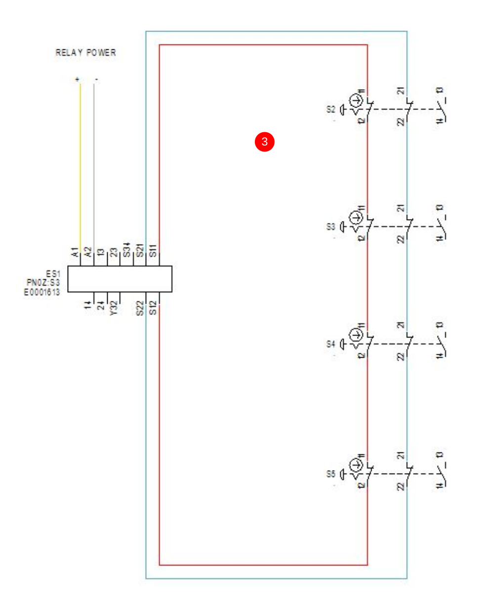
The 'e-stop loop' is a term used for the start and end of the safety circuit. Some systems have 1 loop (single channel) and some have 2 (dual channel). The 'loops' start and end at the safety relay. The most basic funtion of the safety relay is to send out a signal from one of its terminals and if it receives the same signal back on another terminal, it evaluates the circuit as safe. This can be seen in Picture 1. Picture 2 has the same principle, however, the safety relay is now evaluating 2 loops rather than 1. In both pictures, notice there is only 1 safety device connected. In this case, an emergency stop button. To add additonal safety devices, they are simply wired in series before or after another safety device (see Picture 3). The red wires are channel 1 and the blue wires are channel 2. Also notice that the channels always go through Normally Closed (N/C) contacts on any safety device. 'Normally Closed' means that the contact is closed when the device is in its 'Inactive' position. For an emergeny stop button, this condition is when the button is NOT pressed. In a guardswitch, this position is when the key IS inside the switch etc. If you reference Picture 3, N/C contacts allow the signal from terminal S11 to go through all of the emergency stop buttons, and return into S12. The same applies to terminals S21 and S22. This is how the relay evaluates if the circuit is safe or unsafe. If any of the contacts on the emergency stop buttons opens, the signal will be broken and the relay will shut down.

Étape 5 - Safety Status and IO
On newer Stuga machines, each safety device will have a feedback input to the PLC to let the user know which safety device is active. This input is not to be confused with the safety circuit itself. As you can see from Picture 1, we have the estop loops from the previous section but we now have an additional 24Vdc and Input across a Normally Open (N/O) contact on the same button. This contact works in the opposite way to the safety loop contacts. If you look at the symbol, you can see that when the button is in its 'Inactive' state, the 24Vdc line will not be able to pass through to the input. When the button is 'Active (pressed)' the 24Vdc will pass through to the input line and send a 24Vdc signal to the PLC signalling which button has been activated. This is the message that you will see on the user interface of the machine. It is also important to know that the safety relay also provides an input to the PLC to signal whether the safety relay is active (reset) or inactive (shut down). If the input is 'High' from the safety relay, the machine knows that the safety circuit is reset and the machine is safe to run. This can be seen in Picture 2.


Étape 6 - Relay Feedback Loop (Restart Circuit)
**Examples used here include wire colours and wiring principles that apply to the relay used. The principle remains the same for other relay options but wiring colours and terminal connections may differ. See specific machine examples for accurate diagnostic information**
A key function of a safety relay is how it restarts after a shutdown. The function of the restart is determined by how safe the circuit needs to be. Some applications allow an automatic restart of the safety circuit which means as soon as the safety relay evaluates that the circuit is safe, it will automatically restart (reset). The safety circuits on Stuga machines (new and old) all use a manual restart with a reset pushbutton. On older machines (typically the ones that use a single channel circuit) the safety circuit is reset using only a reset button (see Picture 1). On newer machines (typically dual channel machines) a reset button is used and also an interlink with a N/C contact on 2 safety contactors (see Picture 2). In picture 1, if the safety circuit is evaluated as safe, pushing the reset button will restart the relay. In picture 2, if the safety circuit is evaluated as safe, pushing the reset button AND if both K1 and K2 contactors are OFF the relay will restart.
Referencing picture 2, the function of K1 and K2 is controlled by the safety relay. When the safety circuit is restarted, 24Vdc is passed through the safety relay contacts and pulls in the coils on K1 and K2. In turn, this opens the contacts that are used in the feedback loop and closes the contacts that are used for supplying 3 phase power to different equipment such as the saw blade and extraction (see picture 3). When a safety device is triggered, the safety relay will shut down and the 24Vdc which was powering the coils will be dropped and the contactors will open the 3 phase power contacts and close the feedback loop contacts (this is the contactors 'normal' position) (see picture 4). If, for some reason, one of the contactors fails to close one of its contacts, the safety circuit will not be able to restart. This is why it is called a feedback loop and it stops the machine resetting with a faulty safety contactor.


Étape 7 - TwinSAFE System
The TwinSAFE system is a programmable system rather than a hard-wired system. The machines use the same safety devices but they are not evaluated by a safety relay.
The TwinSAFE system treats safety devices as IO devices. An example of this is an emergency stop button. The emergency stop button is wired directly back to an input port on the TwinSAFE slice and the state of the emergency stop button is read by the slice. The emergency stop button is still wired with N/C contacts but there is no N/O for a status feedback as the TwinSAFE system is directly doing the evaluation.
Using various safety IO, the TwinSAFE system is programmed to perform certain actions under certain conditions. In simple terms, if all safety IO meets conditions set in the program, the TwinSAFE system will evaluate this and activate safe outputs (again programmable) which control the safety of the machine.
Wiring the TwinSAFE system is much simpler than a relay system, however, without knowledge of the TwinSAFE programming or how to use this programming for diagnostics, it can be much more difficult to find issues.
The added complication with TwinSAFE is that it works on the EtherCAT system. This means that when there is an issue with the EtherCAT system, the safety circuit will also not reset. The safety circuit not resetting can be a red herring in this system which can be tricky to understand.
Étape 8 - Safety Devices and Wiring
Below is a list of safety devices used on Stuga machines and 'typically' how they are wired and a breif description of how they work.
- Emergency stop buttons - Wired with 2 N/C and 1 N/O contact. The estop loops use the N/C contacts and the feedback (input to PLC) uses the N/O contact.
- Interlock guardswitch - Wired with 2 N/C contacts (out of 3), 1N/O contact and 1 solenoid (Door Unlock). The 2 N/C contacts are split into 2 categories, you have the N/C contact that monitors the state of the solenoid, the N/C contact that monitors the state of the key actuation and a N/C contact that monitors both in series. The N/O contact monitors the state of the key actuation. The solenoid wiring is for unlocking and locking the guardswitch. When no voltage is present on the solenoid wires, the guardswitch will be locked and when voltage is applied, the guardswitch will be unlocked. This is know as a 'power to unlock' guardswitch and this is the type we use on the Stuga machines.
- Guardswitch - Wired with 2 N/C and 1 N/O contact. The estop loops use the N/C contacts and the feedback (input to PLC) uses the N/O contact.
- Safety hinge switch - Wired with 2 N/C and 1 N/O contact. The estop loops use the N/C contacts and the feedback (input to PLC) uses the N/O contact.
- Safety magnetic switch - Wired with 2 N/C and 1 N/O contact. The estop loops use the N/C contacts and the feedback (input to PLC) uses the N/O contact.
Étape 9 - Other Safety Devices
Below is a list of other devices fitted on the Stuga machines which are considered safety related but are not necessarily related or impact the main safety circuit.
- Light curtain - The light curtains are wired with 2 OSSD outputs (Output Signal Switching Device). These are outputs from the light curtain that interact with a designated relay which then controls 2 switches which are wired into the safety circuit. The light curtain is considered part of the safety circuit but it is actually the relay that the light curtain controls which does the safety circuit switching!
- Zero Speed Detector - This is a device that is used to monitor the status of a 3 phase motor. The zero speed detector is not wired into the safety circuit. However, the zero speed detector does stop the interlock guardswitches from unlocking if it does not detect zero speed. It can sometimes be diagnosed that a guardswitch has failed when actually the issue is with the zero speed detector!
- Safety Timer - On some models of the ZX5 you will find a yellow safety timer fitted in the machining centre cabinet. This timer is not wired into the safety circuit but it is controlled by it! This timer allows us a safe amount of time before actuating something. In the case of the machining centre, the timer is used to monitor the safety circuit and when it detects the safety circuit is inactive (emergency stopped pressed for example), it triggers a set time to not allow the door unlock signal to activate. This does 2 things, firstly it only allows the doors to open when the machine is safe and also it allows us to set a time to make sure the machine has come to a complete stop before allowing the doors to open.
Étape 10 - How to Find a Fault with a Safety Circuit (Generic)
There are a number of different ways to find faults with a safety circuit. If you have read through this guide and have another way which you use and works, please add it to this list!
- Continuity test the loops (dead test) **ADD A VIDEO** - As we know, the safety circuit is just 1 or 2 loops that start at the safety relay and end at the safety relay. This means that if we have a complete loop, we will have continuity between the start and end of the loop. If there is no continuity, there is a break in the loop. To test where a fault lies in the system, use a multimeter on the continuity setting (beep function) and start at the safety relay. Each device is wired in series and will come back to a terminal conenction. Find where the first wire goes from the safety relay (wire numbers are key here) and put your first lead on this terminal. The other side of this terminal will be going out to a safety device. Find what device that is (cable numbers and wire tracing) and find out where that wire goes. Once you have found the wire, see what wire comes out of the other side and see where that goes in the cabinet. Once you have these 2 points, you can test continuity between them. If you hear a beep, that safety device contact is working. Do not forget to check both channels if it is a 2 channel system! This test can then be continued through all devices until you do not get a beep. You have then identified A problem (not necessary all of them!). Test all of the devices to make sure you find any and all breaks. Remember, the safety circuit not resetting is not necessarily an issue with the loops!
- Measure the voltages on the loops **ADD A VIDEO** - The channels on a safety relay are typically different voltages and can be measured against each other. If you look at the relay used in step 4, you can use a multimeter on Voltage DC and measure between S11 and S21 and this will give you a voltage. In this method, you are always measuring loop 1 against loop 2 in all devices and rather than listening for a beep, you are looking for a device that returns no voltage.
- Link out the loops - This test is much harder than the first 2 due to having to wire links and move them before and after each test. However, you can do this without a multimeter. If you use the same principle as the continuity test, but rather than always testing across a device, you keep one end of the wire in the relay at all times. This test works best if you link out the entire safety first, then reset, then keep moving one end of the wire back through the safety devices until you are unable to reset.
There are some really important factors to note when fault finding in any scenario. Always be methodical and follow wires and wire numbers. Do not be tempted to jump between different places as it will be hard to keep track and becomes increasingly difficult to log findings. More often than not it is also a waste of time as you end up starting the testing again!
To test the feedback loop on the safety relay, first you can use the continuity test and use a lead at the start of the feedback loop and end of the feedback loop. If the loop is good, you will get a beep when someone presses the reset button. If you do not get a beep, check the continuity over the 2 safety contactors N/C contacts and also the N/O contact of the reset button (it will have to be pressed to beep).
If no multimeter is available, you can link out the feedback loop and the safety relay will automatically reset itself if the safety circuit is complete. If this does work, the wire link can then be used over the 2 safety contactors N/C contacts and the N/O contact of the reset button until it is determined which component has failed.
NEVER LEAVE A MACHINE LINKED OUT. IF THERE IS A SAFETY CIRCUIT ISSUE, THE MACHINE CAN NOT BE USED AND THE COMPONENT WILL NEED TO BE REPLACED AND A FULL SAFETY CIRCUIT FUNCTION TEST WILL NEED TO BE COMPLETED BEFORE PRODUCTION CAN CONTINUE.
Étape 11 - Machine Specific Information
For this document to be valuable and useful, specific information is required from each machine to help make testing easier and quicker for both customers and engineers.
Please add pictures and descriptions to this document and notify Ben who will keep this document tidy and up-to-date.
I hope you see the value in having this document and although it will take time, I hope it will help us all.
Draft
 Français
 English
 Deutsch
 Español
 Italiano
 Português