| [version en cours de rédaction] | [version en cours de rédaction] |
| Ligne 180 : | Ligne 180 : | ||
}} | }} | ||
{{Tuto Step | {{Tuto Step | ||
| − | |Step_Title=<translate></translate> | + | |Step_Title=<translate>Fit drive gear</translate> |
| − | |Step_Content=<translate></translate> | + | |Step_Content=<translate>Fit B0000382 key to shaft |
| + | |||
| + | |||
| + | Fit D0007874 gear to shaft</translate> | ||
| + | |Step_Picture_00=R0000299_Stroke_assembly_rebuild_2024-07-08_08-12-35.png | ||
| + | |Step_Picture_01=R0000299_Stroke_assembly_rebuild_2024-07-08_08-14-13.png | ||
| + | }} | ||
| + | {{Tuto Step | ||
| + | |Step_Title=<translate>Fit fixings</translate> | ||
| + | |Step_Content=<translate>Use M6 x 20 socket countersunk with D0007876 washer | ||
| + | |||
| + | |||
| + | Use M6 x 20 button head with M6x 20 penny washer | ||
| + | |||
| + | |||
| + | Use Loctite 243 and ensure all threads and tapped holes are thoroughly degreased with FE10 solvent | ||
| + | |||
| + | |||
| + | Fit fasteners as shown and tighten both fasteners at the same time, using opposing threads to enable sufficient tensioning</translate> | ||
| + | |Step_Picture_00=R0000299_Stroke_assembly_rebuild_2024-07-08_08-19-06.png | ||
| + | |Step_Picture_01=R0000299_Stroke_assembly_rebuild_2024-07-08_08-20-23.png | ||
| + | |Step_Picture_02=R0000299_Stroke_assembly_rebuild_2024-07-08_08-20-44.png | ||
| + | |Step_Picture_03=R0000299_Stroke_assembly_rebuild_2024-07-08_08-22-55.png | ||
| + | |Step_Picture_04=R0000299_Stroke_assembly_rebuild_2024-07-08_08-23-13.png | ||
| + | }} | ||
| + | {{Tuto Step | ||
| + | |Step_Title=<translate>Degrease faces</translate> | ||
| + | |Step_Content=<translate>Degrease indicated faces with FE10 solvent | ||
| + | |||
| + | |||
| + | Apply 1/3 of tube of M0000603 grease as indicated | ||
| + | |||
| + | |||
| + | Apply Hylomar to face as indicated</translate> | ||
| + | |Step_Picture_00=R0000299_Stroke_assembly_rebuild_2024-07-08_08-24-57.png | ||
| + | |Step_Picture_01=R0000299_Stroke_assembly_rebuild_2024-07-08_08-29-14.png | ||
| + | |Step_Picture_02=R0000299_Stroke_assembly_rebuild_2024-07-08_08-29-55.png | ||
| + | }} | ||
| + | {{Tuto Step | ||
| + | |Step_Title=<translate>Attach to main housing</translate> | ||
| + | |Step_Content=<translate>Combine 2 assemblies as shown. | ||
| + | |||
| + | |||
| + | Use location dowels to position | ||
| + | |||
| + | |||
| + | Fix with 3 off M8 70 socket caps and Loctite 243 | ||
| + | |||
| + | |||
| + | Smooth excess Hylomar with clean rag once fasteners have been finalised</translate> | ||
| + | |Step_Picture_00=R0000299_Stroke_assembly_rebuild_2024-07-08_08-31-43.png | ||
| + | |Step_Picture_01=R0000299_Stroke_assembly_rebuild_2024-07-08_08-33-10.png | ||
| + | |Step_Picture_02=R0000299_Stroke_assembly_rebuild_2024-07-08_08-33-36.png | ||
| + | }} | ||
| + | {{Tuto Step | ||
| + | |Step_Title=<translate>Fit B0000380 bearing to housing</translate> | ||
| + | |Step_Content=<translate>1 Fit 1 off B0000380 bearing to D0007797 as shown. Ensure correct bearing fit is observed | ||
| + | |||
| + | |||
| + | 2 Fit to D0007750 backplate and secure with 4 off M6 x 16 socket countersunk | ||
| + | |||
| + | |||
| + | 3 Fit D0007730 spindle | ||
| + | |||
| + | |||
| + | 4 Fit D0007729 spacer | ||
| + | |||
| + | |||
| + | 5 Fit 2nd B0000380 bearing</translate> | ||
| + | |Step_Picture_00=R0000299_Stroke_assembly_rebuild_2024-07-08_08-40-58.png | ||
| + | |Step_Picture_01=R0000299_Stroke_assembly_rebuild_2024-07-08_08-41-29.png | ||
| + | |Step_Picture_02=R0000299_Stroke_assembly_rebuild_2024-07-08_08-41-51.png | ||
| + | |Step_Picture_03=R0000299_Stroke_assembly_rebuild_2024-07-08_08-42-17.png | ||
| + | |Step_Picture_04=R0000299_Stroke_assembly_rebuild_2024-07-08_08-43-35.png | ||
}} | }} | ||
{{Notes}} | {{Notes}} | ||
Version du 8 juillet 2024 à 09:45
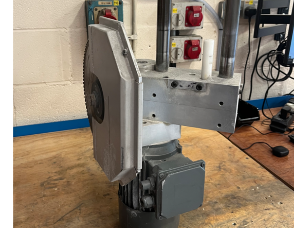
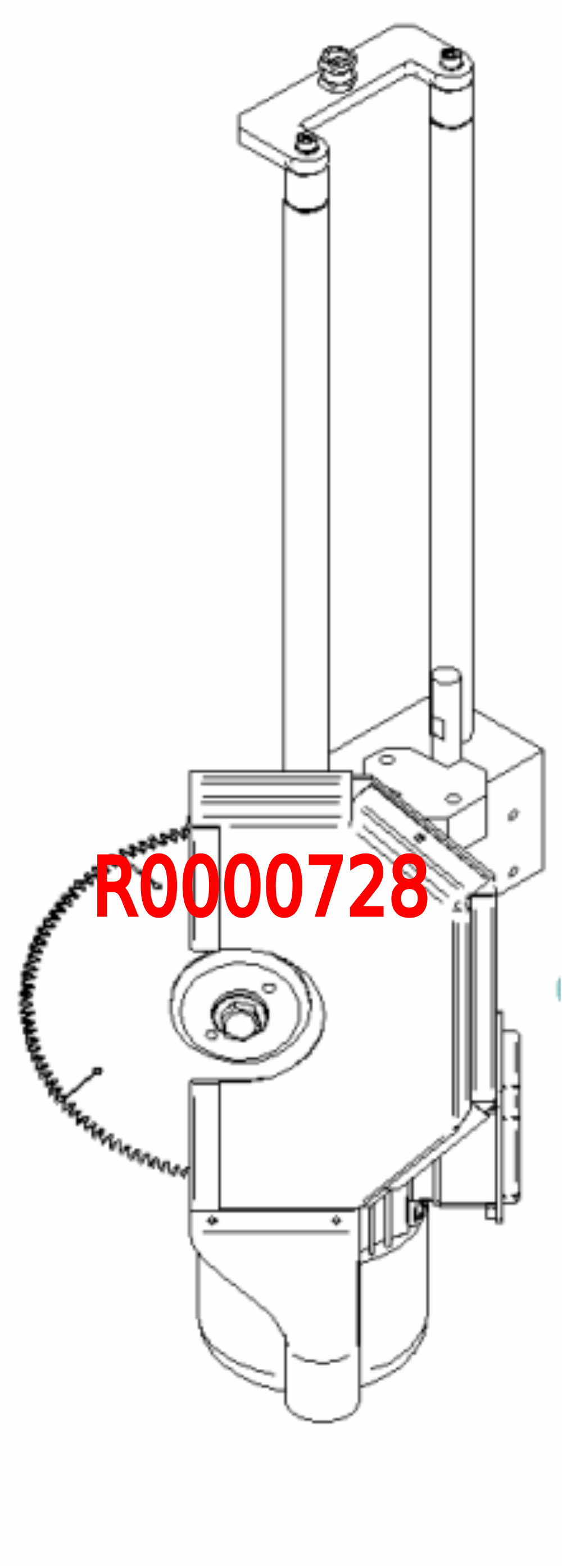
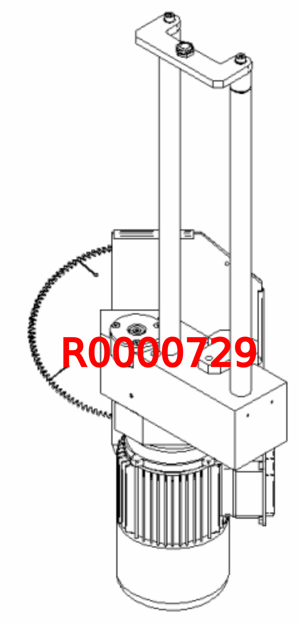
Instructions for correct assembly and setting of stroke assembly gearboxes Original part numbers R0000728 and R0000729

Difficulté
Très difficile
Durée
4 heure(s)
Sommaire
- 1 Introduction
- 2 Étape 1 - Handing clarification
- 3 Étape 2 - Unless otherwise stated
- 4 Étape 3 - Motor Drive pinion
- 5 Étape 4 - Fit Motor Drive gear Housing
- 6 Étape 5 - Fit B0000043 Bearings
- 7 Étape 6 - Fit B0000105 bearing
- 8 Étape 7 - Bevel gear identification
- 9 Étape 8 - Fit Gear to shaft
- 10 Étape 9 - Fit shaft assembly to housing
- 11 Étape 10 - Degrease faces
- 12 Étape 11 - Fit and seal shaft assembly
- 13 Étape 12 - Fit drive gear
- 14 Étape 13 - Fit fixings
- 15 Étape 14 - Degrease faces
- 16 Étape 15 - Attach to main housing
- 17 Étape 16 - Fit B0000380 bearing to housing
- 18 Commentaires
Introduction
The following instructions should be followed to ensure that correct assembly and setting are performed
Tools / consumables Required
Standard hex key set
Standard spanner set
Large adjustable spanner
Drifts and punches
Ballpein hammer
Soft hammer
FE10 Solvent
Hylomar Gasket
Parts Required
Kit R0000299 containing
B0000043 Double Angular bearing 15 I?D 35 O?D 15.9 long rubber seal 3 x 2
B0000105 Double Angular Bearing 15 I/D 35 O/D 15.9 Long x 1
B0000335 3ph Brake motor 2 pole 3000rpm x 1
B0000380 Double Angular Bearing 25 I/D 52 O/D 20.6 Long + rubber seal x 2
D0000059 Damper Bridge x 1
D0000062 Damper Bridge Boss x 2
D0007730 ZX4 V Notch Mk1 Spindle Shaft x1
D0007867 Bevel Gear (Left) x 1
D0007868 Bevel Gear (Right ) x 1
D0007873 Motor Gear x 1
D0007874 Pinion Gear x 1
D0007875 Pinion Shaft x 1Étape 1 - Handing clarification
R0000728 and R0000729 are mirror images to each other
Please inspect pictures to clarify and confirm correct hand to be built
(Supplied unit to be refurbished will always be rebuilt as the same hand )
Étape 2 - Unless otherwise stated
Always use Loctite 243 on all fasteners fitted unless stated different
All bearings should be an acceptable fit, with Loctite 641 and FE10 solvent used if required
All fasteners should be marked once finalised

Étape 3 - Motor Drive pinion
1 Check fit of Motor drive gear D0007873 onto B0000335 motor. Ensure fit is smooth and pinion can be fitted by hand.
2 If gear does not fit onto spindle by hand, remove key from motor shaft and
- Check motor gear fits on shaft with no key present. If not rework bore of motor gear to ensure correct fitment
- Check key passes through motor gear keyway . If not rework keyway until key passes through by hand
- Re fit key and check motor gear now fits by hand onto motor shaft
3 Set motor pinion flush to top of shaft and secure with 2 off M6 x 10 KCP grubscrews and Loctite 243. Ensure these are fully tightened


Étape 4 - Fit Motor Drive gear Housing
1 Degrease mounting faces indicated with FE10 solvent
2 Apply bead of Hylomar as shown to drive pinion housing
3 Fit housing to motor, paying attention to orientation and fix with 4 off M6 x 50 socket caps


Étape 5 - Fit B0000043 Bearings
Fit 2 off B0000043 bearings to housing D0007870
Ensure correct bearing fitment is achieved. Use loctite 641 and thoroughly degrease with FE10 is bearing are loose in bore

Étape 6 - Fit B0000105 bearing
Fit B0000105 bearing to shaft D0007875 , ensuring correct orientation
Use loctite 641 and FE10 if bearing fit is loose

Étape 7 - Bevel gear identification
Ensure bevel gears are identified correctly
D0007868 has an additional raised face on the rear of the gear

Étape 8 - Fit Gear to shaft
Fit Key B0000383 to Shaft , and fit bevel gear D0007868 , ensuring correctly orientated


Étape 9 - Fit shaft assembly to housing
Fit assembled shaft to bearing housing as shown
Again, observe fit of bearings and if required, use Loctite 641 bearing fit and FE10 solvent to correct if bearings are loose


Étape 10 - Degrease faces
Degrease indicated faces with FE10 solvent


Étape 11 - Fit and seal shaft assembly
Apply Hylomar as shown
Apply Loctite 641 to bearing
Fit assembly to main housing


Étape 12 - Fit drive gear
Fit B0000382 key to shaft
Fit D0007874 gear to shaft


Étape 13 - Fit fixings
Use M6 x 20 socket countersunk with D0007876 washer
Use M6 x 20 button head with M6x 20 penny washer
Use Loctite 243 and ensure all threads and tapped holes are thoroughly degreased with FE10 solvent
Fit fasteners as shown and tighten both fasteners at the same time, using opposing threads to enable sufficient tensioning


Étape 14 - Degrease faces
Degrease indicated faces with FE10 solvent
Apply 1/3 of tube of M0000603 grease as indicated
Apply Hylomar to face as indicated


Étape 15 - Attach to main housing
Combine 2 assemblies as shown.
Use location dowels to position
Fix with 3 off M8 70 socket caps and Loctite 243
Smooth excess Hylomar with clean rag once fasteners have been finalised


Étape 16 - Fit B0000380 bearing to housing
1 Fit 1 off B0000380 bearing to D0007797 as shown. Ensure correct bearing fit is observed
2 Fit to D0007750 backplate and secure with 4 off M6 x 16 socket countersunk
3 Fit D0007730 spindle
4 Fit D0007729 spacer
5 Fit 2nd B0000380 bearing


Draft
 Français
 English
 Deutsch
 Español
 Italiano
 Português