| [version en cours de rédaction] | [version en cours de rédaction] |
| Ligne 28 : | Ligne 28 : | ||
D0004972 None Centralise Bracket x 1 | D0004972 None Centralise Bracket x 1 | ||
| − | + | D0004622 centralise cylinder spacer x 1 | |
R0000572 Bench Assemble Centralise Assembly | R0000572 Bench Assemble Centralise Assembly | ||
Version du 19 juin 2024 à 11:34
Centralise mounting details


Difficulté
Moyen
Durée
1 heure(s)
Sommaire
- 1 Introduction
- 2 Étape 1 - Unless otherwise stated
- 3 Étape 2 - Attach centralise cylinder bracket
- 4 Étape 3 - Attach centralise lever
- 5 Étape 4 - Position centralise bar
- 6 Étape 5 - Attach Tie Rod
- 7 Étape 6 - Fit centralise switch bracket
- 8 Étape 7 - Attach damper and None Centralise Bracket
- 9 Commentaires
Introduction
Tools Required
Standard hex key set
Standard spanner set
Steel rule 600mm
Soft hammer
Parts Required
D0004672 Centralise Sensor Bracket x 1
D0004972 None Centralise Bracket x 1
D0004622 centralise cylinder spacer x 1
R0000572 Bench Assemble Centralise Assembly
Étape 1 - Unless otherwise stated
Use locktite 243 on all fasteners
Use loctite 572 on all threaded pneumatic connection
Pen mark all fasteners to show finalised

Étape 2 - Attach centralise cylinder bracket
Attach d0004542 bracket to frame as shown . Use 2 off M8 x 40 socket caps with A form washers

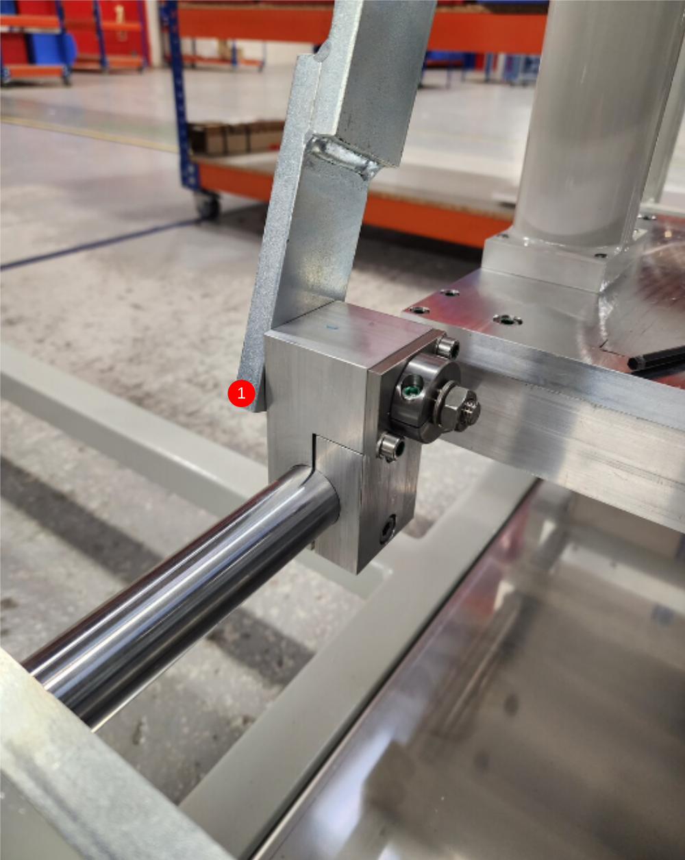
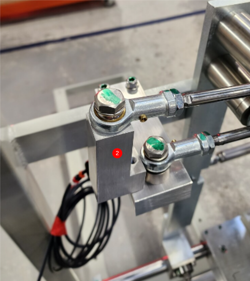
Étape 3 - Attach centralise lever
1 Attach prebuilt centralise lever to bottom turntable shaft, use 2 off M8 x35 socket caps to mount clamp , but do no add tension to fasteners
2 Attach cylinder rod end to centralise bracket as shown using 1 off M10 x 50 set bolt and A form washer . Fit spacer D0004407 between block and spherical bearing . Do not add adhesive to this fastener yet

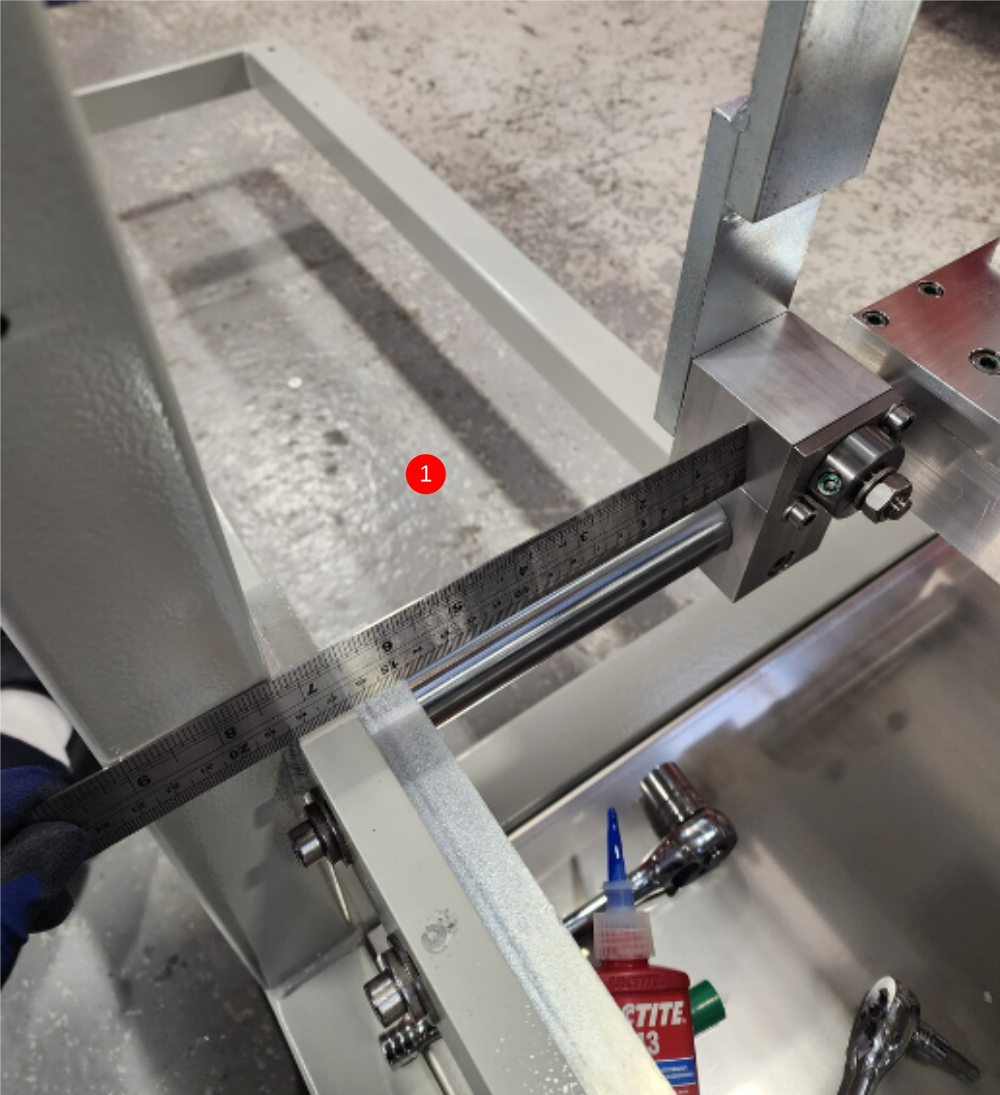
Étape 4 - Position centralise bar
1 Set position of centralise bar to 145mm on bottom shaft
2 Finalise tension on clamp bracket . ENSURE fasteners are tightened equally as this clamp can effect position of top cylinder when tensioned
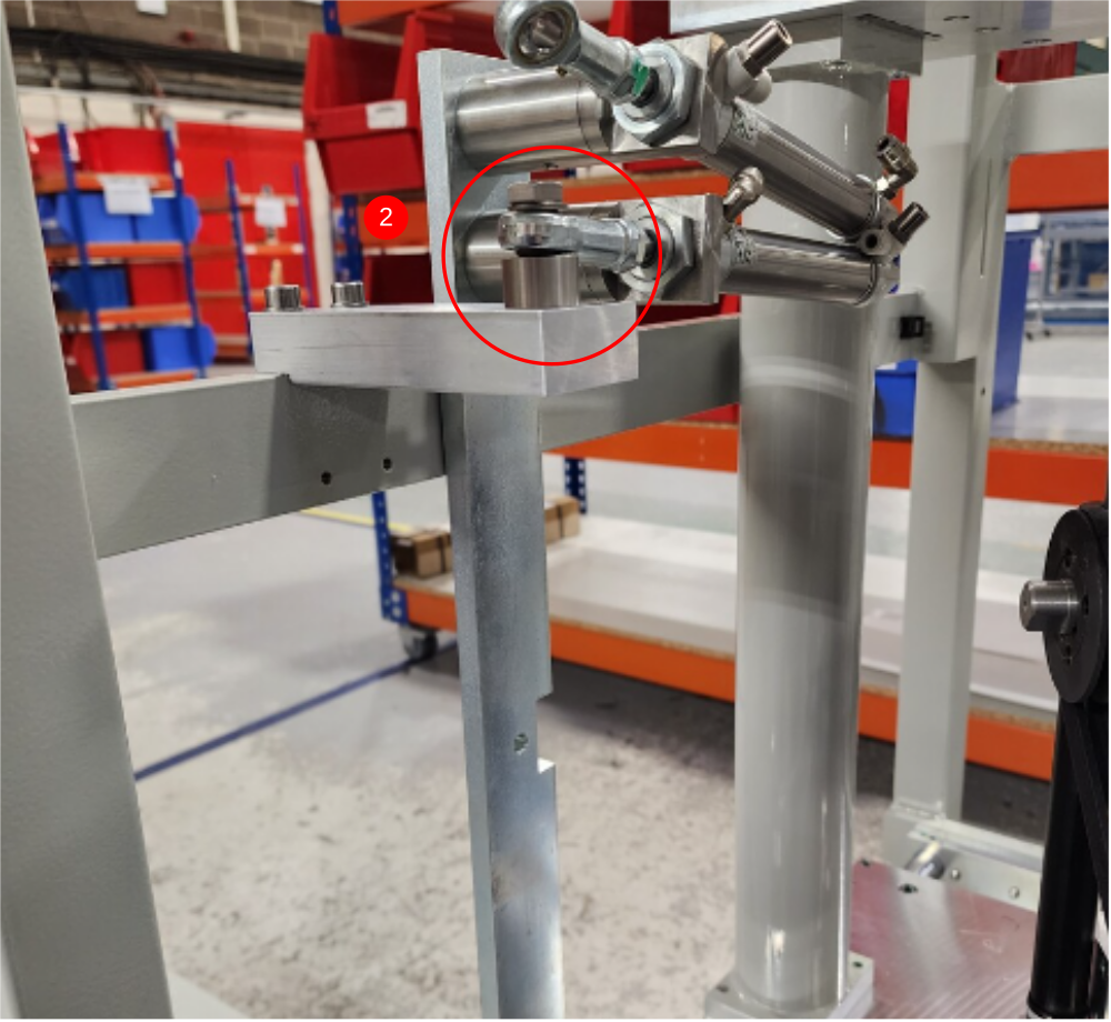
3 Check cylinder position by removing indicated ?M10 set bolt and spacer and checking that spherical bearing is still aligned to M10 tapped hole when cylinder is in a fully closed position
4 Add adhesive to M10 set bolt and finalise bolt
5 Check movement is free and consistent with cylinder attached


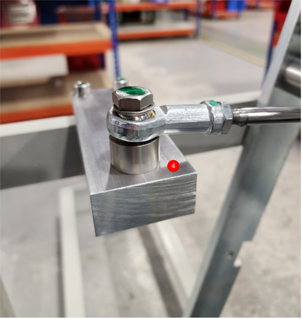
Étape 5 - Attach Tie Rod
Attach tie rod to spindle post and centralise bar as shown
Use fixings as follows
1 M10 x 30 set bolt, A Form washer, Spherical bearing 2 x M10 A form washer
2 Attach end shown (Non adjustable end ) to saw post
3 Attach end shown (adjustable end ) to centralise bar

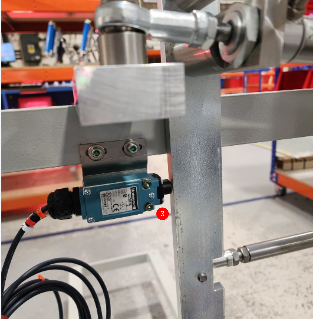
Étape 6 - Fit centralise switch bracket
1 Fit centralise switch bracket to frame using 2 off M5 x 16 socket caps and heavy M5 washers.
2 Fit pre wired X203 switch assembly (from electrical department ) To bracket using 2 off M4 x 40 socket caps, 4 A form washers and 2 off M4 nyloc nuts
3 Set switch position so roller plunge is just made when centralise lever is in its most forward position

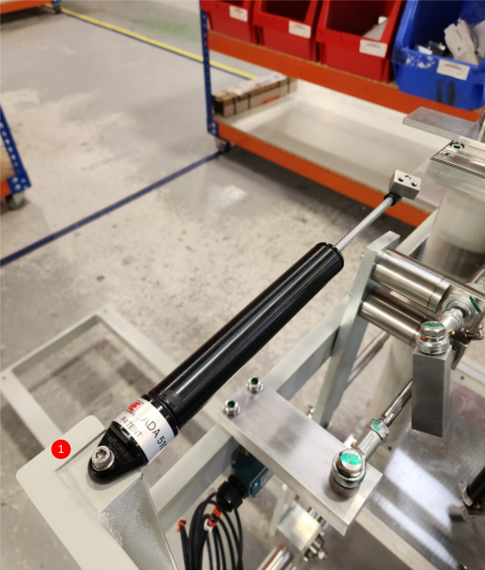
Étape 7 - Attach damper and None Centralise Bracket
1 Attach pre built damper to frame using M6 x 35 socket cap reduced in length by 10mm, M6 A form washer and Securing M5 x 12 flat grubscrew.
Do not fully tension M6 , as movement is required by damper. Hold position of M6 with M5 grubscrew
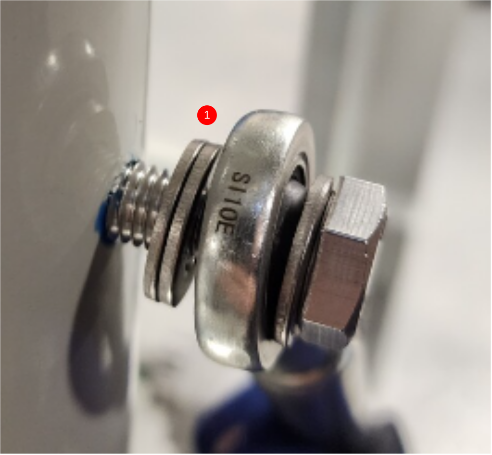
2 Fix None Centralise Bracket to top cylinder as shown using M10 x 30 set bolt and A form washer

Draft
 Français
 English
 Deutsch
 Español
 Italiano
 Português