| [version en cours de rédaction] | [version en cours de rédaction] |
| Ligne 75 : | Ligne 75 : | ||
|Step_Picture_00=R0015272_1st_Stage_fitting_Saw_Outfeed_Screenshot_2023-10-10_094127.png | |Step_Picture_00=R0015272_1st_Stage_fitting_Saw_Outfeed_Screenshot_2023-10-10_094127.png | ||
|Step_Picture_01=R0015272_1st_Stage_fitting_Saw_Outfeed_Screenshot_2023-10-10_094251.png | |Step_Picture_01=R0015272_1st_Stage_fitting_Saw_Outfeed_Screenshot_2023-10-10_094251.png | ||
| + | }} | ||
| + | {{Tuto Step | ||
| + | |Step_Title=<translate>Check and fit M8 rivnuts</translate> | ||
| + | |Step_Content=<translate>Fit 2 off rivnuts to required mounting points for conveyor . | ||
| + | |||
| + | |||
| + | 2 off M8 rivnuts must be installed correctly | ||
| + | |||
| + | |||
| + | 1 Face of frame must be countersunk to allow flush fitment and full contact of rivnut shoulder. | ||
| + | |||
| + | 2 Rivnuts must be tensioned correctly when installed. If in doubt, please request information from supervisor for the correct fitting of rivnuts. | ||
| + | |||
| + | 3 Rivnuts should have a solid fixed into frame and not be able to rotate . To check this, bolt a component to the rivnut and tighten. Then undo fastener and remove component. Rivnut should not move during this process and remain solid</translate> | ||
| + | |Step_Picture_00=R0008013_Clacker_assembly_quality.png | ||
| + | |Step_Picture_01=ZX5_Production_R0000548E_Module_G_to_R0015040_Module_F_alignment_Screenshot_2024-01-10_084541.png | ||
| + | |Step_Picture_01_annotation={"version":"2.4.6","objects":[{"type":"image","version":"2.4.6","originX":"left","originY":"top","left":0,"top":0,"width":373,"height":583,"fill":"rgb(0,0,0)","stroke":null,"strokeWidth":0,"strokeDashArray":null,"strokeLineCap":"butt","strokeDashOffset":0,"strokeLineJoin":"miter","strokeMiterLimit":4,"scaleX":1.61,"scaleY":1.61,"angle":0,"flipX":false,"flipY":false,"opacity":1,"shadow":null,"visible":true,"clipTo":null,"backgroundColor":"","fillRule":"nonzero","paintFirst":"fill","globalCompositeOperation":"source-over","transformMatrix":null,"skewX":0,"skewY":0,"crossOrigin":"","cropX":0,"cropY":0,"src":"https://stuga.dokit.app/images/2/2f/ZX5_Production_R0000548E_Module_G_to_R0015040_Module_F_alignment_Screenshot_2024-01-10_084541.png","filters":[]},{"type":"textbox","version":"2.4.6","originX":"center","originY":"center","left":281.25,"top":159.86,"width":172.57,"height":101.25,"fill":"#FF0000","stroke":"#FF0000","strokeWidth":1,"strokeDashArray":null,"strokeLineCap":"butt","strokeDashOffset":0,"strokeLineJoin":"miter","strokeMiterLimit":4,"scaleX":2.99,"scaleY":2.99,"angle":0,"flipX":false,"flipY":false,"opacity":1,"shadow":null,"visible":true,"clipTo":null,"backgroundColor":"","fillRule":"nonzero","paintFirst":"fill","globalCompositeOperation":"source-over","transformMatrix":null,"skewX":0,"skewY":0,"text":"This is INCORRECT. Should be countersunk","fontSize":20,"fontWeight":"normal","fontFamily":"sans-serif","fontStyle":"normal","lineHeight":1.16,"underline":false,"overline":false,"linethrough":false,"textAlign":"left","textBackgroundColor":"","charSpacing":0,"minWidth":20,"styles":{} },{"type":"wfellipse","version":"2.4.6","originX":"center","originY":"center","left":309,"top":390,"width":200,"height":200,"fill":"rgba(255,0,0,0)","stroke":"#FF0000","strokeWidth":2,"strokeDashArray":null,"strokeLineCap":"butt","strokeDashOffset":0,"strokeLineJoin":"miter","strokeMiterLimit":4,"scaleX":1,"scaleY":1,"angle":0,"flipX":false,"flipY":false,"opacity":1,"shadow":null,"visible":true,"clipTo":null,"backgroundColor":"","fillRule":"nonzero","paintFirst":"fill","globalCompositeOperation":"source-over","transformMatrix":null,"skewX":0,"skewY":0,"rx":100,"ry":100}],"height":938,"width":600} | ||
}} | }} | ||
{{Tuto Step | {{Tuto Step | ||
Version actuelle datée du 10 janvier 2024 à 10:51
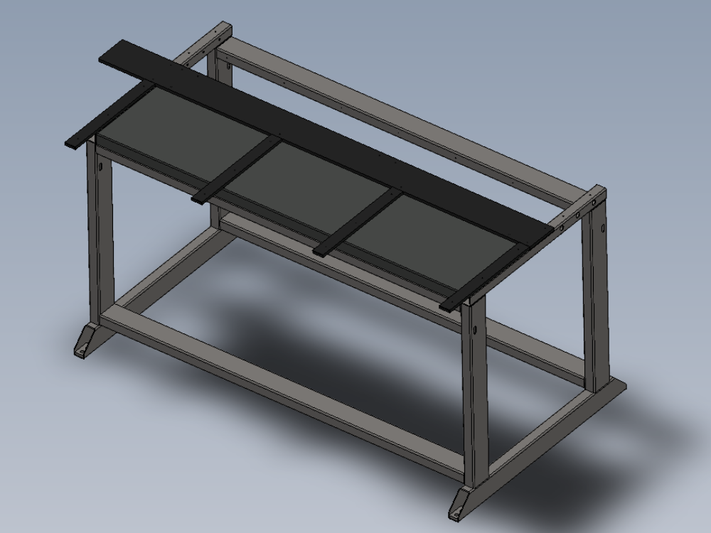
Assembly details for 1st stage fitting

Difficulté
Moyen
Durée
3 heure(s)
Sommaire
Introduction
Tools Required
Standard Hex key set
Standard HSS Drill Set
Standard spanner set
Standard Tap set
Standard 5mm straight hex key ( non ball point )
Hex key extension bar
Parts Required
D0004583 Outfeed Long Rest (5354) x 1
D0004584 Outfeed Side Rest x 4
D0005127 Outfeed Welded Frame (5356) x 1
H0005136 Outfeed Top Tray (5355) x 1
Étape 1 - Unless otherwise stated
Use Loctite 243 on all fasteners
Use Loctite 570 on all threaded pneumatic connections
Pen mark all bolts when finalised

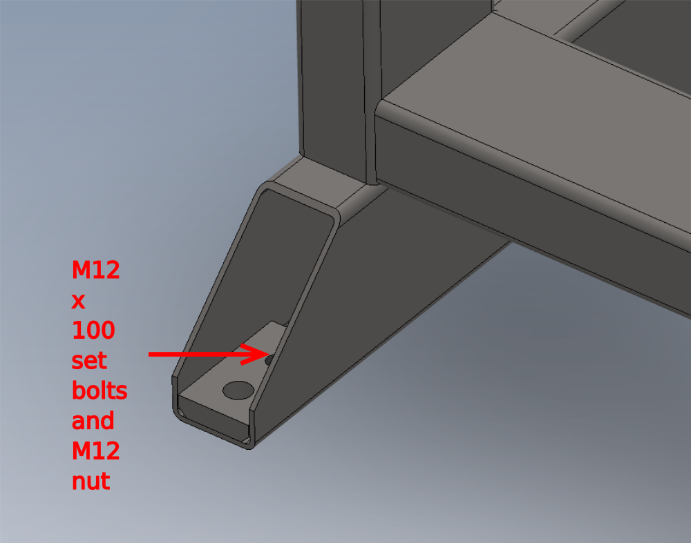
Étape 2 - Clean and tap
Use taps to clean all threads present on frame .
Add 4 off m12 x 100 set bolts with M12 nuts and fit to adjusting points
Use 4 off levelling pads (workshop stock ) to sit beneath adjustment bolts
(pictures required please)

Étape 3 - Ecr work
Ecr raised 10/10/23 to add 2 off M4 tapped holes to frame.
Until processed add by hand as shown


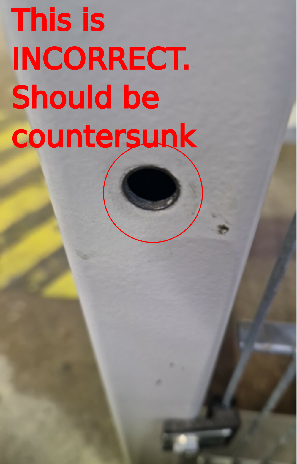
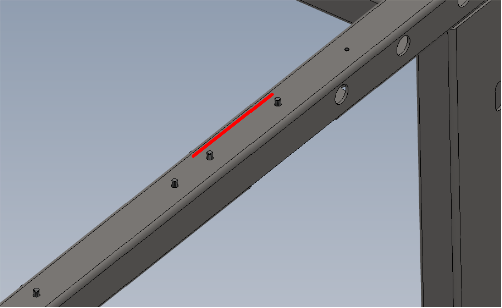
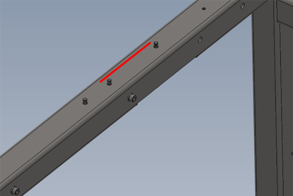
Étape 4 - Check and fit M8 rivnuts
Fit 2 off rivnuts to required mounting points for conveyor .
2 off M8 rivnuts must be installed correctly
1 Face of frame must be countersunk to allow flush fitment and full contact of rivnut shoulder.
2 Rivnuts must be tensioned correctly when installed. If in doubt, please request information from supervisor for the correct fitting of rivnuts.
3 Rivnuts should have a solid fixed into frame and not be able to rotate . To check this, bolt a component to the rivnut and tighten. Then undo fastener and remove component. Rivnut should not move during this process and remain solid

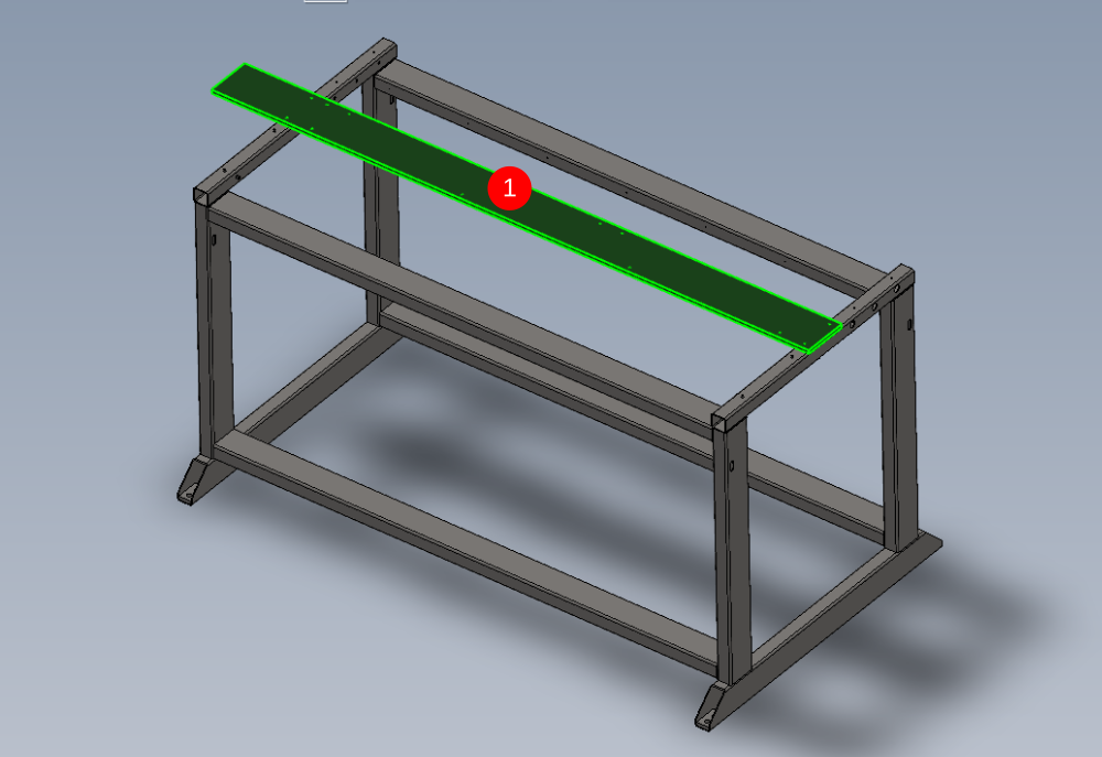
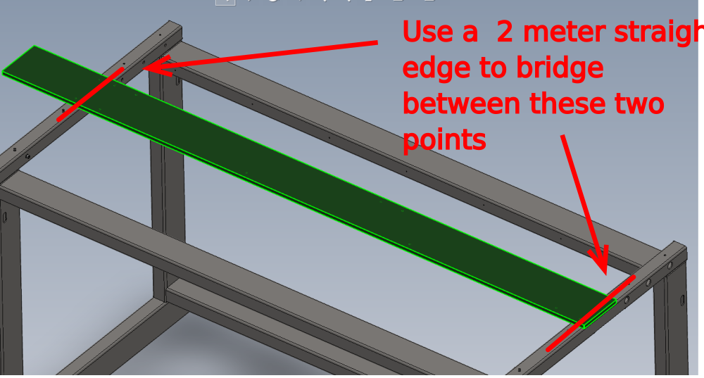
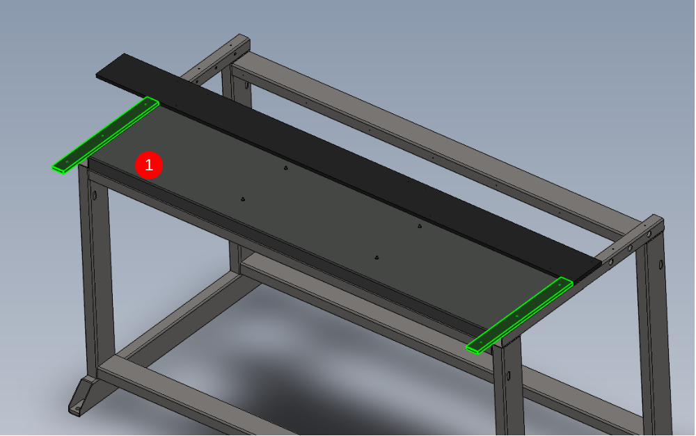
Étape 5 - Mount and check long rest plate
Fit D0004583 Outfeed Long Rest orientated as shown
Tap all holes in long rest before fitting . Only use a plug tap to clean threads in long rest
1 Use 4 off M6 x 12 socket caps with M6 A washers and fix to frame
2 Check flatness with 2 meter straight edge across 2 indicated points.
Straight edge will show a gap in the centre section of the long rest bar
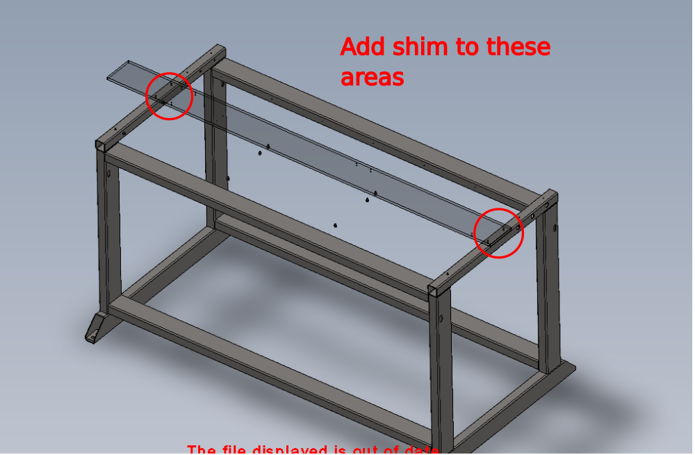
Étape 6 - Adjust Outfeed long rest
Shims can be used to adjust the flatness of the long rest plate
Cut shims to 10mm x 140mm
Place at indicated points between frame and long rest bar .
Re tension bolts once shim is added to show true reflection of change made by shim added
Adjust until long rest bar is flat to straight edge
Tolerance + - 1mm
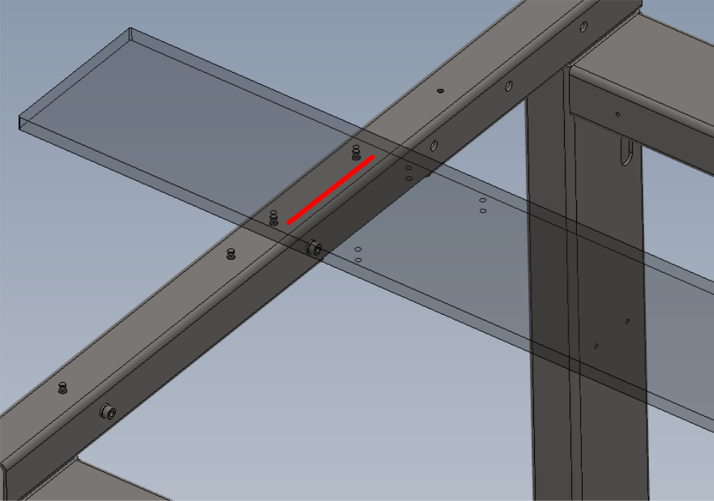
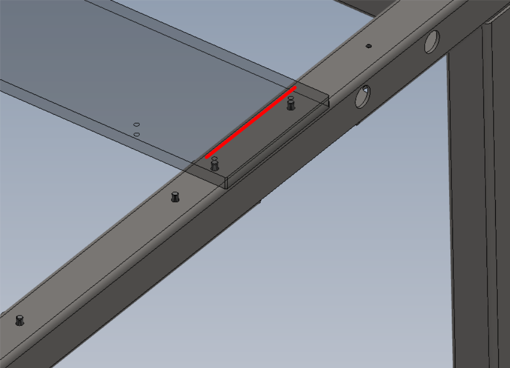
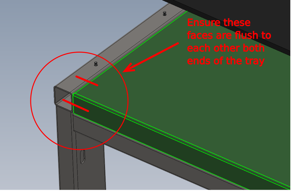
Étape 7 - Fit outfeed top tray
Fit H0005136 Outfeed Top Tray as shown
Ensure indicated faces are set flush to frame
Use 8 off M6 x 12 socket caps and heavy M6 washers to fix to frame

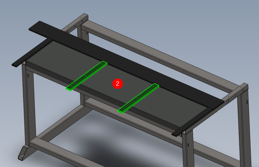
Étape 8 - Fit side rests
Fit 4 of D0004584 Outfeed Side Rest to positions indicated
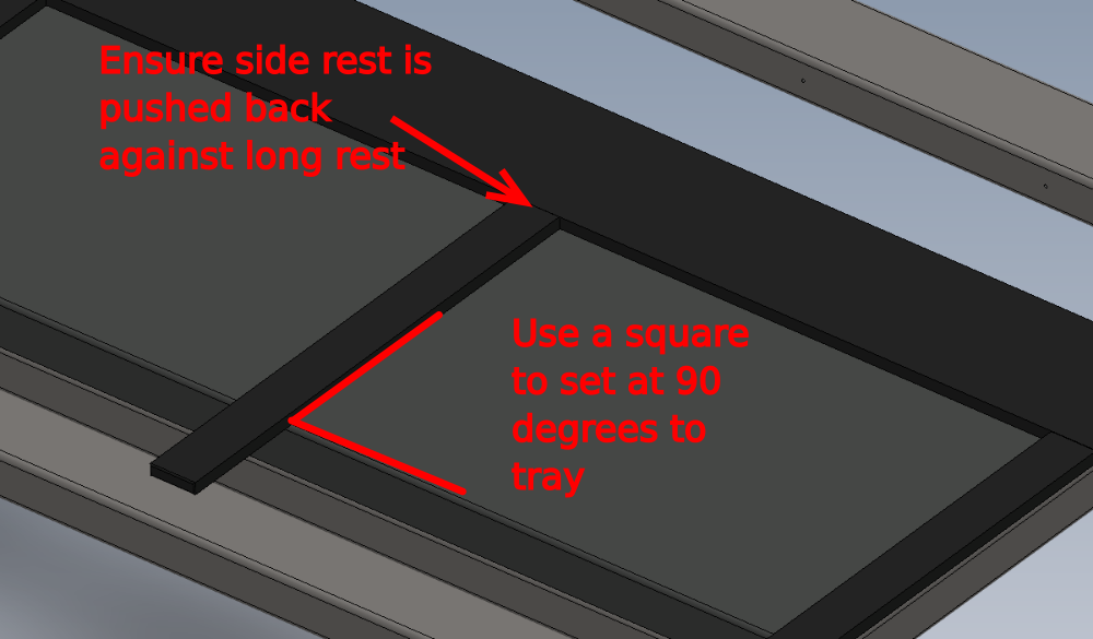
When fitting side rests ensure that they are set as shown S
1 Use M6 x 10 socket caps (4 off) to fit indicated arms to frame
2 Use M6 x 12 socket caps and penny washers (4 off) to fit indicated side rests

Draft
 Français
 English
 Deutsch
 Español
 Italiano
 Português