| [version en cours de rédaction] | [version en cours de rédaction] |
(Page créée avec « {{Tuto Details |Main_Picture=R0015343_Waste_Guidance_Installation_Screenshot_2023-10-31_135102.png |Main_Picture_annotation={"version":"2.4.6","objects":[{"type":"image","... ») |
|||
| Ligne 48 : | Ligne 48 : | ||
Pen mark all fasteners to show finalised</translate> | Pen mark all fasteners to show finalised</translate> | ||
|Step_Picture_00=R0015086_Assemble_Pneumatics_on_to_electrical_cabinet_loctite_243.png | |Step_Picture_00=R0015086_Assemble_Pneumatics_on_to_electrical_cabinet_loctite_243.png | ||
| + | }} | ||
| + | {{Tuto Step | ||
| + | |Step_Title=<translate>Please note</translate> | ||
| + | |Step_Content=<translate>Drive motor must be removed to allow access to fit side sheets | ||
| + | |||
| + | |||
| + | 1 locking grubscrew must be slackened to allow drive motor to be removed. | ||
| + | |||
| + | |||
| + | Ensure drive motor is refitted after installation of waste guidance sheets</translate> | ||
| + | |Step_Picture_00=R0015338_Bench_Assemble_Serial_Plate_caution.png | ||
}} | }} | ||
{{Tuto Step | {{Tuto Step | ||
| Ligne 149 : | Ligne 160 : | ||
{{Notes}} | {{Notes}} | ||
{{PageLang | {{PageLang | ||
| + | |Language=en | ||
|SourceLanguage=none | |SourceLanguage=none | ||
|IsTranslation=0 | |IsTranslation=0 | ||
| − | |||
}} | }} | ||
{{Tuto Status | {{Tuto Status | ||
|Complete=Draft | |Complete=Draft | ||
}} | }} | ||
Version du 4 décembre 2023 à 14:50
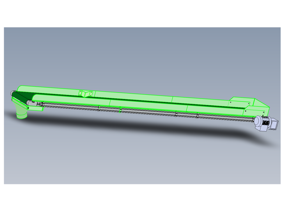
Installation details of waste guidance

Difficulté
Moyen
Durée
2 heure(s)
Sommaire
- 1 Introduction
- 2 Étape 1 - Unless otherwise stated
- 3 Étape 2 - Please note
- 4 Étape 3 - Fit Radius side sheets
- 5 Étape 4 - Fit side sheets
- 6 Étape 5 - Fit deflector
- 7 Étape 6 - Position end plate
- 8 Étape 7 - Drill end plate
- 9 Étape 8 - Fit end plate
- 10 Étape 9 - Fit edging strip
- 11 Étape 10 - Fit lower swarf funnel brackets
- 12 Étape 11 - Add riv nuts
- 13 Étape 12 - Fit swarf funnel
- 14 Étape 13 - Drill and pin
- 15 Étape 14 - Check all fasteners
- 16 Commentaires
Introduction
Tools Required
Standard hex key set
Standard spanner set
Standard HSS drill set
Standard tap set
Parts Required
D0001967 Conveyor End Plate x 1
D0001970 Swarf Funnel Support x 2
D0005616 Conveyor Swarf Funnel x 1
D0010843 Conveyor Deflector Plate x 1
M0000031 Panel Edging Strip; 9 x 6mm (consumable stock )
R0015344 Bench Assemble Conveyor Parts
Étape 1 - Unless otherwise stated
Use Loctite 243 on all fasteners
Use Loctite 572 on all threaded pneumatic connection
Pen mark all fasteners to show finalised

Étape 2 - Please note
Drive motor must be removed to allow access to fit side sheets
1 locking grubscrew must be slackened to allow drive motor to be removed.
Ensure drive motor is refitted after installation of waste guidance sheets

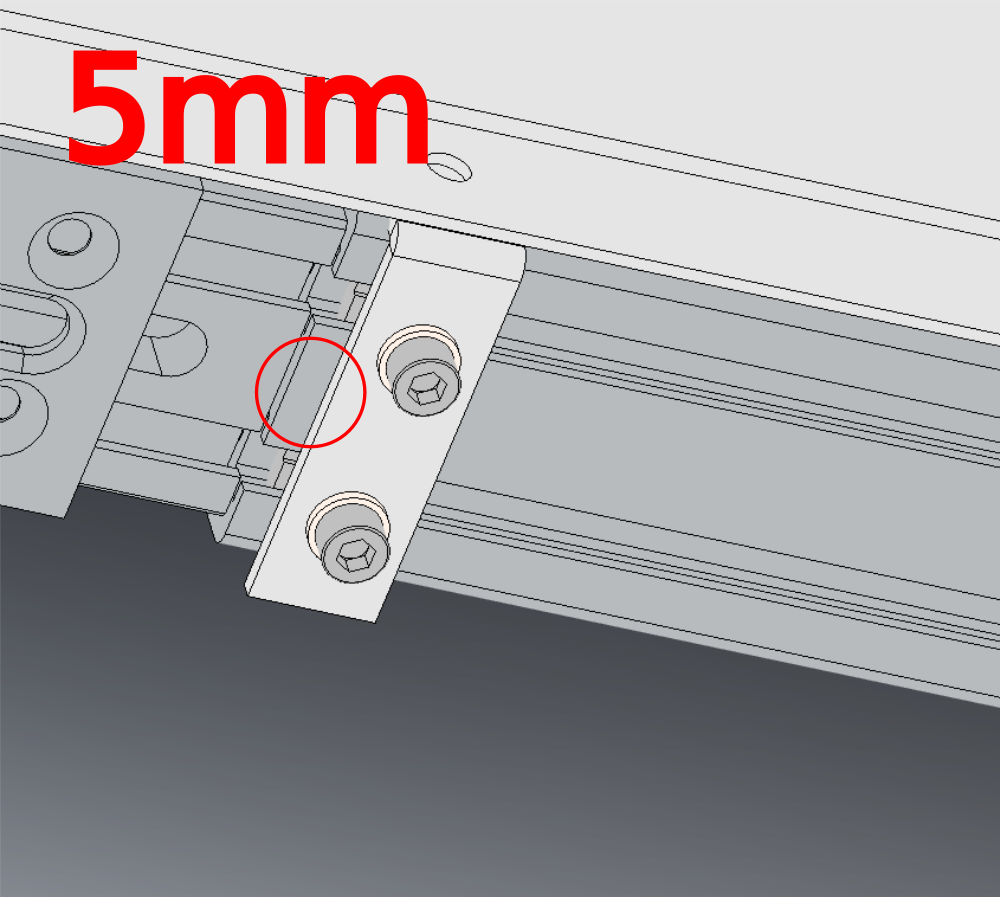
Étape 3 - Fit Radius side sheets
fit 2 off radius side sheets as shown
Secure using m5 d nuts
Position as shown 5mm from edge frame


Étape 4 - Fit side sheets
Fit 4 off side sheet as shown


Étape 5 - Fit deflector
Drill and fit deflector as shown
Provide details to enable ecr to be raised to add mounting holes

Étape 6 - Position end plate
Position conveyor end plate as shown
Ensure end plate does not touch belt
Mark positions for mounting holes and remove end plate

Étape 7 - Drill end plate
Drill M6 clearance holes at marked points
Drill off cable tie bases for motor cable
Provide all details to enable ecr generation

Étape 8 - Fit end plate
Ensure button head M6 fasteners are used backed with m6 nuts
Étape 9 - Fit edging strip
Fit edging strip to top faces
please detail

Étape 10 - Fit lower swarf funnel brackets
secure with M5 caps and d nuts


Étape 11 - Add riv nuts
Add 2 off m6 rivnuts to swarf funnel

Étape 12 - Fit swarf funnel
Fit swarf funnel to conveyor brackets
Secure with M6 cap heads and washers
Picture required for correct setting position of funnel

Étape 13 - Drill and pin
Drill and pin funnel in position with 2 off 3 mm spiral pins
Étape 14 - Check all fasteners
Check all fasteners are finalised and marked
Ensure all settings have been finalised

Draft
 Français
 English
 Deutsch
 Español
 Italiano
 Português