| [version en cours de rédaction] | [version en cours de rédaction] |
m (Gareth Green a déplacé la page Rotary Ring pneumatic test vers R0015300 Rotary Ring pneumatic test) |
|||
| Ligne 11 : | Ligne 11 : | ||
{{Materials}} | {{Materials}} | ||
{{EPI}} | {{EPI}} | ||
| + | {{Tuto Step | ||
| + | |Step_Title=<translate>Lubrication</translate> | ||
| + | |Step_Content=<translate>All lubrication points should be greased | ||
| + | |||
| + | |||
| + | 2 pumps of grease to be added to each linear bearing | ||
| + | |||
| + | |||
| + | 24 off bearings in total | ||
| + | |||
| + | |||
| + | 4 off bearings per double slide base | ||
| + | |||
| + | |||
| + | 2 off bearings per single slide base</translate> | ||
| + | |Step_Picture_00=R0015320_Pneumatic_Output_Test_Screenshot_2023-11-06_113551.png | ||
| + | }} | ||
{{Tuto Step | {{Tuto Step | ||
|Step_Title=<translate>Connect air feed</translate> | |Step_Title=<translate>Connect air feed</translate> | ||
Version du 6 novembre 2023 à 13:48
Pneumatic function test for Rotary Ring

Difficulté
Moyen
Durée
1 heure(s)
Sommaire
Étape 1 - Lubrication
All lubrication points should be greased
2 pumps of grease to be added to each linear bearing
24 off bearings in total
4 off bearings per double slide base
2 off bearings per single slide base

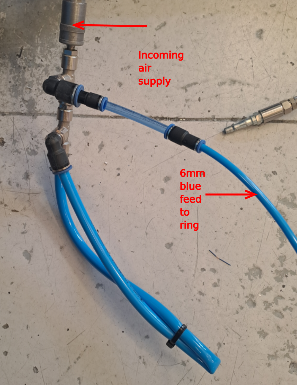
Étape 2 - Connect air feed
Compressed air feed needs connecting to main 6mm blue feed pipe to ring.
Use adapter to enable safe connection via PCL coupling and probe
Étape 3 - Check for air leaks
When air is connect to rotary ring, attention should be paid to any audible air leaks. If any are present, identify source and rectify
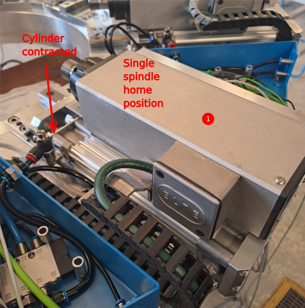
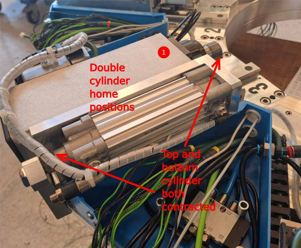
Étape 4 - Home positions
1 When air is connected, all cylinders should be in a contracted state. This is their home position
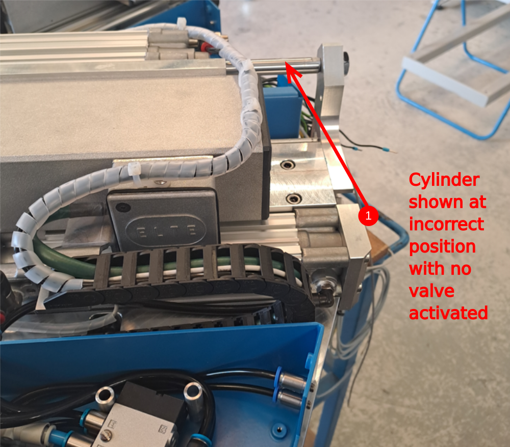
Étape 5 - Home position correction
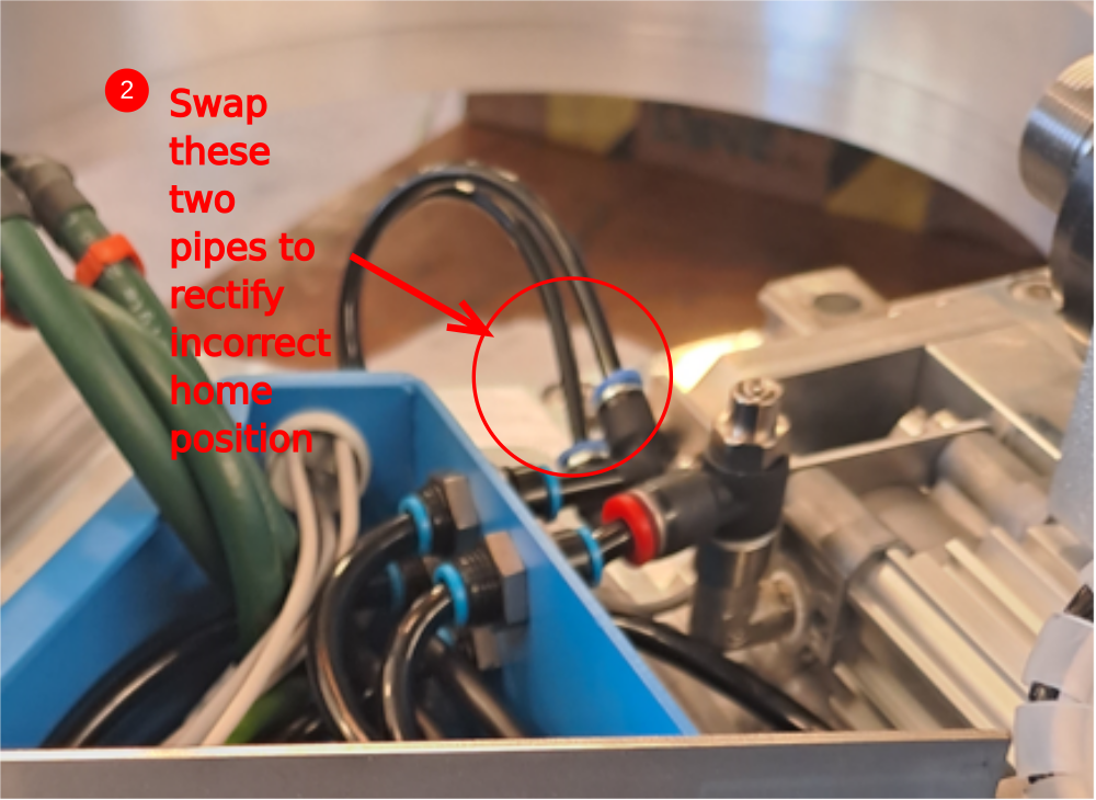
If correct practice has been followed, only the double slide cylinder will have the possibility of being at the incorrect home position . This is easily rectified
1 Image shows incorrect position when air has been connected to mains supply
2 To rectify, disconnect mains air feed and swap the two indicated pipes at the stem elbows
3 Reconnect air and confirm correct home position is now achieved
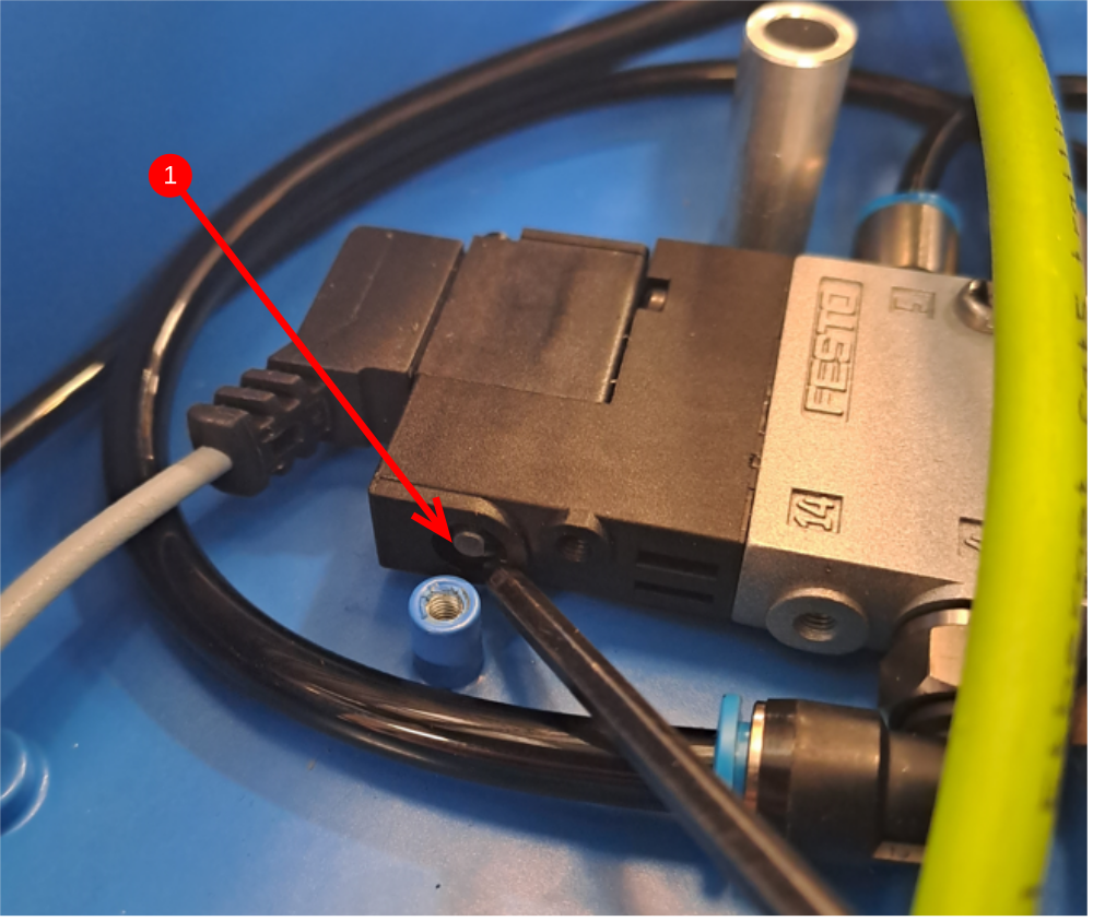
Étape 6 - Manual valve activation
Valves can be activated manually by the control button. When pressed, the valve will fire the associated cylinder to its active position .
1 Manual valve activation button
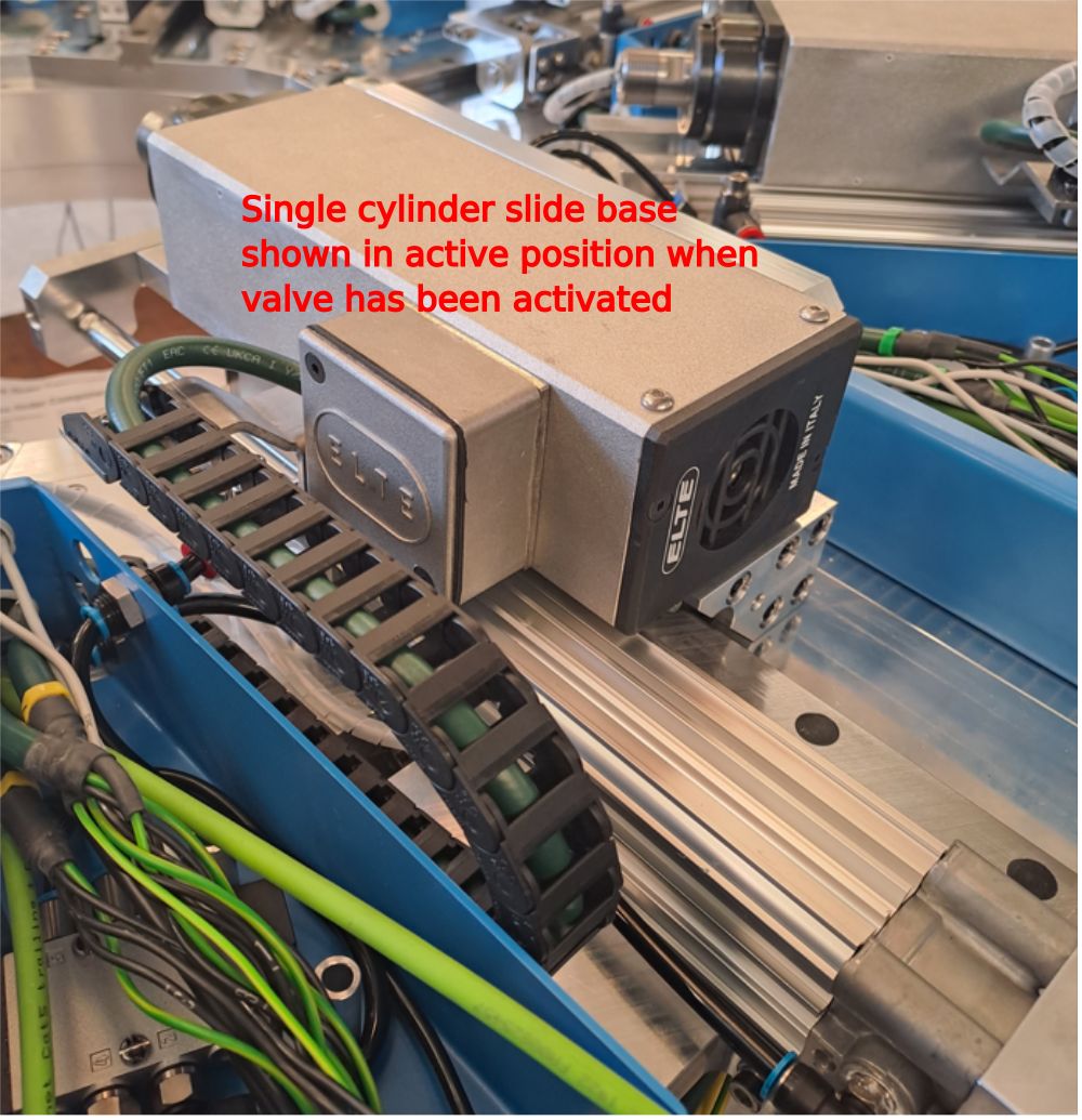
Étape 7 - Test single slide bases
4 off
Check that when valve is activated, spindle assembly goes to the position shown. Fire valve a few times to check movement is consistent. Cylinder speeds and cushioning will be set at a later point
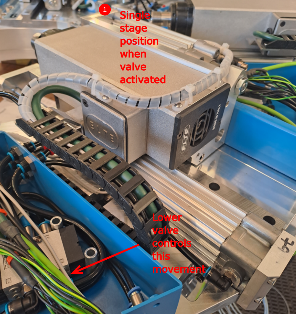
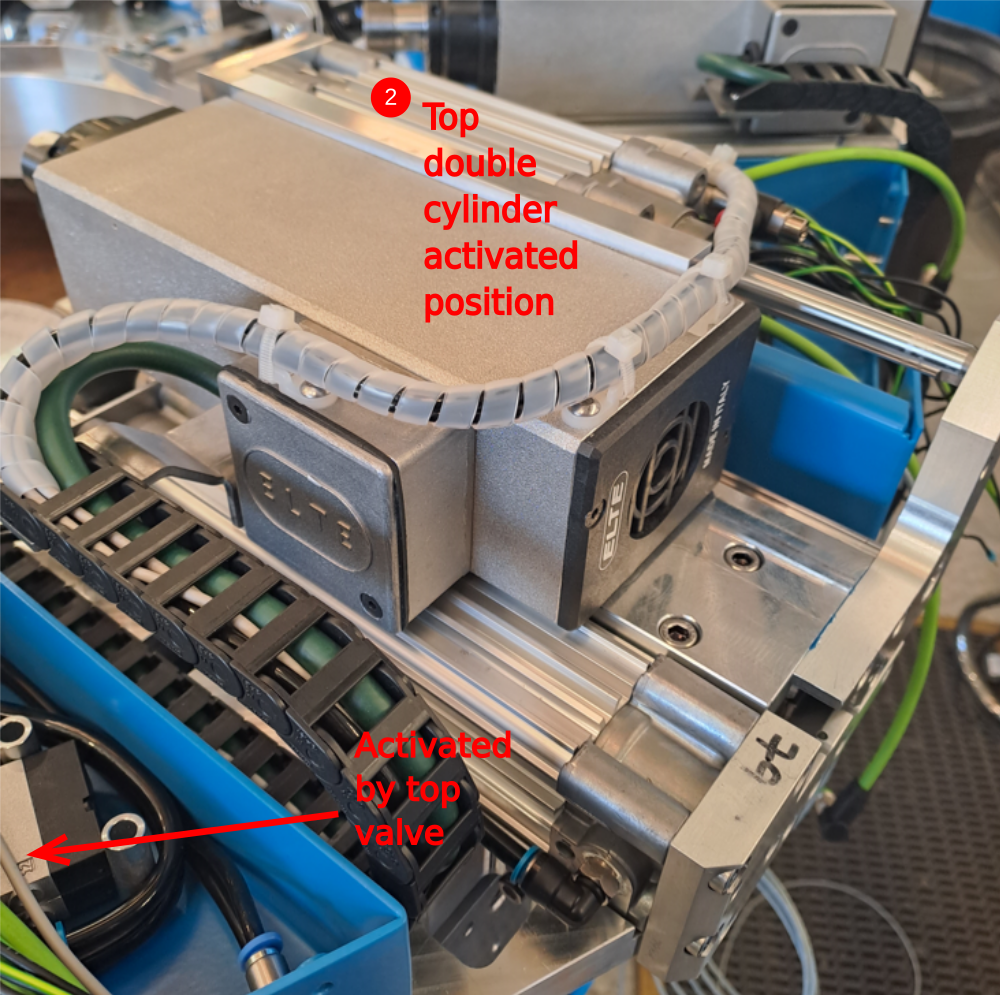
Étape 8 - Test double slide bases
4 off
Check that when valve is activated, spindle assembly goes to the position shown. Fire valve a few times to check movement is consistent. Cylinder speeds and cushioning will be set at a later point
1 Single stage cylinder activated by lower valve , see image for details
2 Double stage cylinder activated by upper valve , see image for details
Étape 9 - Disconnect air
Once pneumatic testing is complete disconnect the air supply
Draft
 Français
 English
 Deutsch
 Español
 Italiano
 Português