| [version en cours de rédaction] | [version en cours de rédaction] |
| Ligne 67 : | Ligne 67 : | ||
| − | Use Drawing shown for positions , and images for orientation</translate> | + | Use Drawing shown for positions , and images for orientation |
| + | |||
| + | Ensure drawing is followed for positions of sensors. These measurements are to set the sensors in a standard position. Commission team may alter these on test, but for production adhere to measurements given</translate> | ||
|Step_Picture_00=R0015266B_mount_completed_assemblies_large-1000004904.jpg | |Step_Picture_00=R0015266B_mount_completed_assemblies_large-1000004904.jpg | ||
|Step_Picture_00_annotation={"version":"2.4.6","objects":[{"type":"image","version":"2.4.6","originX":"left","originY":"top","left":0,"top":0,"width":1280,"height":577,"fill":"rgb(0,0,0)","stroke":null,"strokeWidth":0,"strokeDashArray":null,"strokeLineCap":"butt","strokeDashOffset":0,"strokeLineJoin":"miter","strokeMiterLimit":4,"scaleX":0.47,"scaleY":0.47,"angle":0,"flipX":false,"flipY":false,"opacity":1,"shadow":null,"visible":true,"clipTo":null,"backgroundColor":"","fillRule":"nonzero","paintFirst":"fill","globalCompositeOperation":"source-over","transformMatrix":null,"skewX":0,"skewY":0,"crossOrigin":"","cropX":0,"cropY":0,"src":"https://stuga.dokit.app/images/d/d8/R0015266B_mount_completed_assemblies_large-1000004904.jpg","filters":[]}],"height":270,"width":600} | |Step_Picture_00_annotation={"version":"2.4.6","objects":[{"type":"image","version":"2.4.6","originX":"left","originY":"top","left":0,"top":0,"width":1280,"height":577,"fill":"rgb(0,0,0)","stroke":null,"strokeWidth":0,"strokeDashArray":null,"strokeLineCap":"butt","strokeDashOffset":0,"strokeLineJoin":"miter","strokeMiterLimit":4,"scaleX":0.47,"scaleY":0.47,"angle":0,"flipX":false,"flipY":false,"opacity":1,"shadow":null,"visible":true,"clipTo":null,"backgroundColor":"","fillRule":"nonzero","paintFirst":"fill","globalCompositeOperation":"source-over","transformMatrix":null,"skewX":0,"skewY":0,"crossOrigin":"","cropX":0,"cropY":0,"src":"https://stuga.dokit.app/images/d/d8/R0015266B_mount_completed_assemblies_large-1000004904.jpg","filters":[]}],"height":270,"width":600} | ||
| Ligne 79 : | Ligne 81 : | ||
{{Tuto Step | {{Tuto Step | ||
|Step_Title=<translate>Mount Loader wheel assembly</translate> | |Step_Title=<translate>Mount Loader wheel assembly</translate> | ||
| − | |Step_Content=<translate>Mount loader wheel assemble to frame Using socket caps | + | |Step_Content=<translate>Mount loader wheel assemble to frame Using M10 x 30 socket caps with large M10 penny washers (40mm diameter) |
Version du 17 août 2023 à 15:12
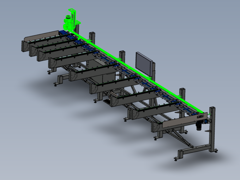
Instructions to mount pre built assemblies to frame

Difficulté
Moyen
Durée
2 heure(s)
Introduction
Tools Required
Standard hex key set
Parts Required
D0015432 Spacer: Ø25.4 x 100mm (12.7mm ID) x 10
D0015479 Sensor Mount Rail 1450 mm Long x 4
D0015480 Sensor Mount Rail 825 Long x 1
F0000299 T Nut Sub Insert M6 (Fat) x 16
R0015030B Bench Assembly Loader Wheel
R0015080 Bench assemble sensor rail
R0015271 Mount buffer bars ( pre fitted to frame )
R0015351 Mount monitor to frame (pre fitted to frame)Étape 1 - Unless otherwise stated
Use loctite 243 on all fasteners
Use Loctite 572 on all threaded pneumatic connections
Pen mark all bolts to show finalised

Étape 2 - Attach sensor rail 1
Use M10 x 120 socket caps to secure sensor rail parts to frame
Attach D0015480 Sensor Mount Rail 825 Long with 2 off D0015432 Spacer: Ø25.4 x 100mm (12.7mm ID)
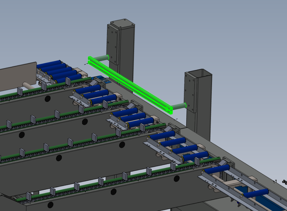
Étape 3 - Attach sensor rails
Use M10 x 120 socket caps to secure sensor rail parts to frame
Attach 4 off D0015479 Sensor Mount Rail 1450 mm Long with 8 off D0015432 Spacer: Ø25.4 x 100mm (12.7mm ID)


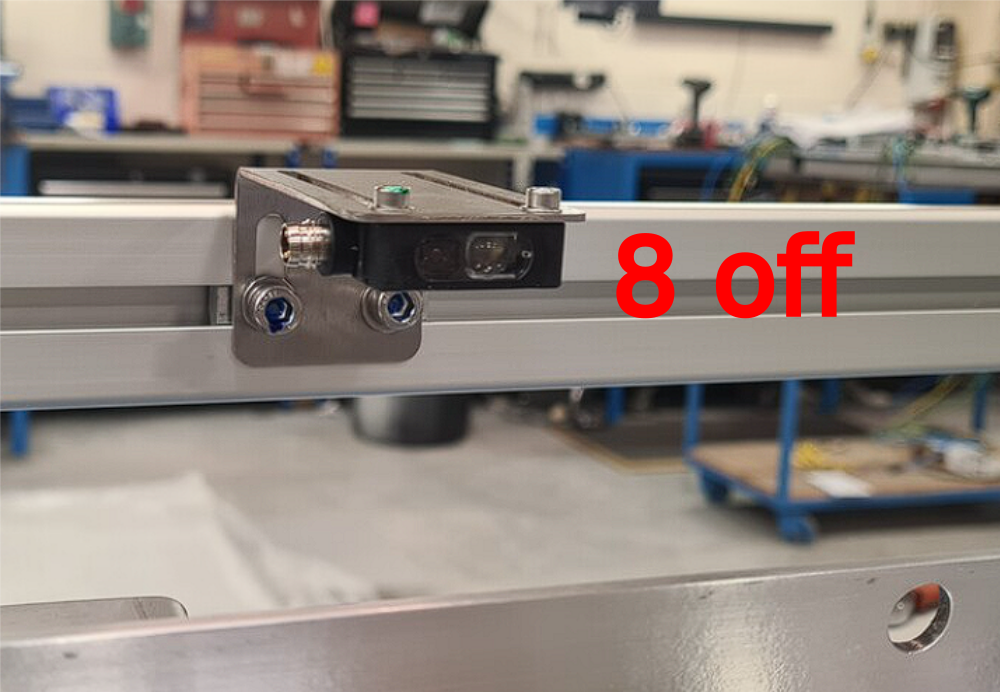
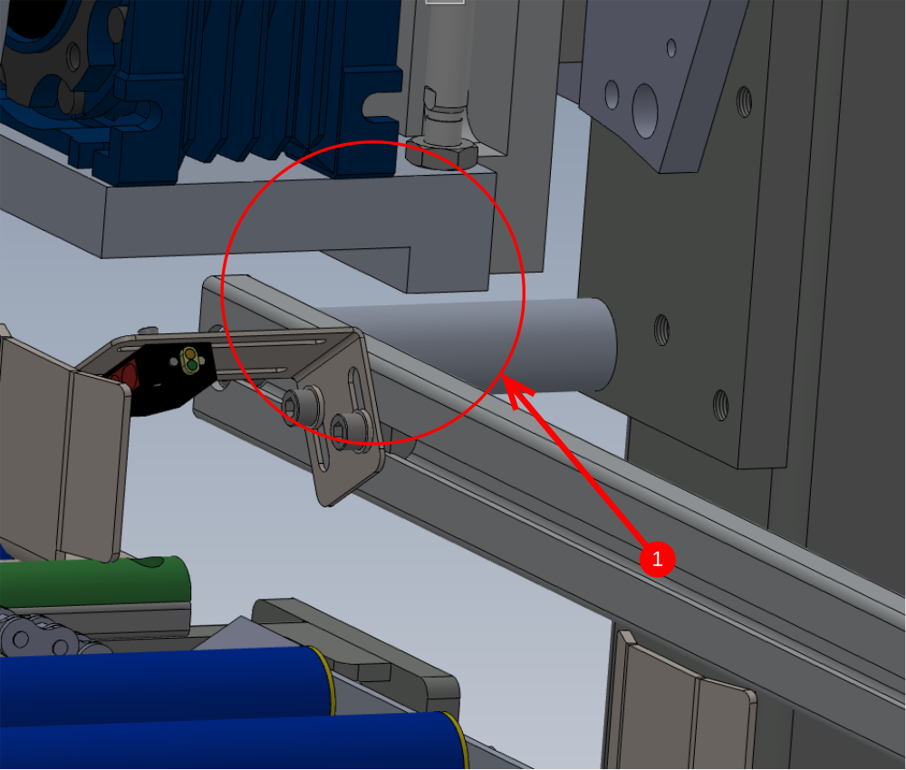
Étape 4 - Mount sensors
Mount sensors from assembly R0015080 with F0000299 M6 D nuts and M6 x 12 socket caps with A form washers
Use Drawing shown for positions , and images for orientation
Ensure drawing is followed for positions of sensors. These measurements are to set the sensors in a standard position. Commission team may alter these on test, but for production adhere to measurements given


Étape 5 - Mount Loader wheel assembly
Mount loader wheel assemble to frame Using M10 x 30 socket caps with large M10 penny washers (40mm diameter)
Quality check
1 When loader wheel pulley is in its lowest position it must not hit the sensor rail assembly. If contact is evident follow step 2
2 Use Washers as spacers ( size required ) to lift the assembly up from the frame mounting point and create clearance between the loader wheel and the sensor rail

Draft
 Français
 English
 Deutsch
 Español
 Italiano
 Português