| [version en cours de rédaction] | [version en cours de rédaction] |
| Ligne 8 : | Ligne 8 : | ||
}} | }} | ||
{{Introduction | {{Introduction | ||
| − | |Introduction=<translate>On Autoflow 2 Sawing Centres, | + | |Introduction=<translate>On Autoflow 2 Sawing Centres following 5 years of use., it has been found that the internal saw centre framework can lose its rigidity. this is probably due to "bruising" or denting of the aluminium joints introducing a slight amount of play. This is exacerbated by the design where it is attached and driven on from the base up |
| − | |||
| − | ==== Parts required: ==== | + | A retrofit kit of parts has previously been created to allow additional reinforcement to be introduced within the structural framework. This kit builds upon the first kit to provide further accuracy enhancements by |
| + | |||
| + | # Adding left right stability with additional slide rails at the top of the subframe | ||
| + | # Adding front / back stability by moving the SY axis leadscrew to the same height as the saw table | ||
| + | |||
| + | ====Parts required: ==== | ||
R0010272 Kit: Saw Frame Rigidity Pt 2 | R0010272 Kit: Saw Frame Rigidity Pt 2 | ||
| Ligne 31 : | Ligne 35 : | ||
}} | }} | ||
{{Tuto Step | {{Tuto Step | ||
| − | |Step_Title=<translate> | + | |Step_Title=<translate>SY axis Assembly</translate> |
| − | + | |Step_Content=<translate></translate> | |
| − | |||
| − | |||
| − | |||
| − | |||
| − | |||
| − | |Step_Content=<translate> | ||
|Step_Picture_00=TB0301_Autoflow_Saw_Head_Reinforcement_-_Additional_Enhancements_03014.jpg | |Step_Picture_00=TB0301_Autoflow_Saw_Head_Reinforcement_-_Additional_Enhancements_03014.jpg | ||
}} | }} | ||
Version du 6 novembre 2020 à 19:58
Autoflow Saw Head Reinforcement – Additional Enhancements

Difficulté
Moyen
Durée
30 minute(s)
Introduction
On Autoflow 2 Sawing Centres following 5 years of use., it has been found that the internal saw centre framework can lose its rigidity. this is probably due to "bruising" or denting of the aluminium joints introducing a slight amount of play. This is exacerbated by the design where it is attached and driven on from the base up
A retrofit kit of parts has previously been created to allow additional reinforcement to be introduced within the structural framework. This kit builds upon the first kit to provide further accuracy enhancements by
- Adding left right stability with additional slide rails at the top of the subframe
- Adding front / back stability by moving the SY axis leadscrew to the same height as the saw table
Parts required:
R0010272 Kit: Saw Frame Rigidity Pt 2
This kit consists of 2 carriage assemblies, specifically designed to provide further rigidity to the top of the Saw Head Assembly. In addition, 2 mounting blocks required to relocate the Saw Y Axis Assembly are also included. This allows the Saw Y Axis Assembly to continue to operate accurately, but improves the life of associated components.Étape 1 - Rails to be loosely installed
The 2 carriage assemblies are as shown. First, the rails need to be loosely installed onto the horizontal Maytec extrusion, allowing for lateral adjustment. Parts D0010710, D00010711 and B0000046 are to be assembled, as shown. Two of these sub-assemblies are required.
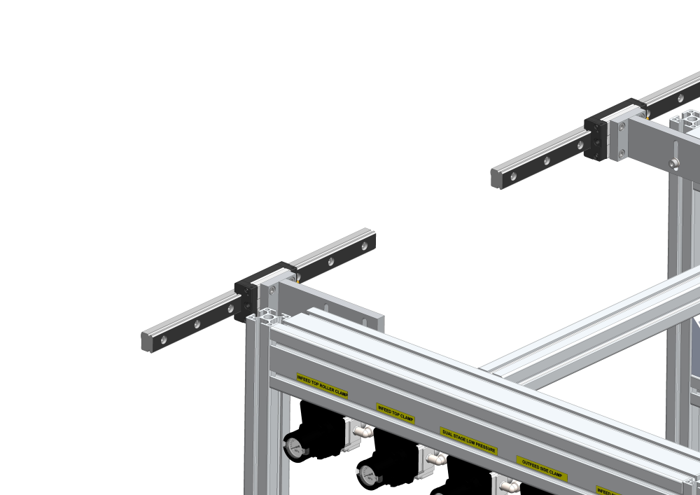
Étape 2 - Bolt to Saw Head Assembly
These are then slid onto the rails and the D0010711 parts can then be bolted to the Saw Head Assembly. Note, the grease nipples are pointing inwards in both instances. The rails can now be tightened up.

Étape 3 - SY axis Assembly

Étape 4 - Higher accuracy and associated component life
The combination of these 2 new parts allows the assembly to be installed in the following position, resulting in a further improvement of accuracy and associated component life.

Draft
 Français
 English
 Deutsch
 Español
 Italiano
 Português