| [version en cours de rédaction] | [version en cours de rédaction] |
| Ligne 37 : | Ligne 37 : | ||
{{Tuto Step | {{Tuto Step | ||
|Step_Title=<translate>Setting the Motor Overload Relay</translate> | |Step_Title=<translate>Setting the Motor Overload Relay</translate> | ||
| − | |Step_Content=<translate></translate> | + | |Step_Content=<translate>Using the example motor from the above step, this Overload Relay would need to be set to 3.00A. |
| + | |||
| + | <br /> | ||
| + | |||
| + | * Lift the plastic cover that covers the dial to the left hand side of the rocker switch. | ||
| + | * Using a small screwdriver, turn the dial to the required amperage (or as close as possible!) It is better to set the dial slightly over than slightly under if you cannot get it exact. | ||
| + | * Replace cover</translate> | ||
| + | |Step_Picture_00=Setting_Motor_Overload_Relays_20201006_100600.jpg | ||
| + | |Step_Picture_00_annotation={"version":"2.4.6","objects":[{"type":"image","version":"2.4.6","originX":"left","originY":"top","left":-32,"top":-516,"width":4032,"height":3024,"fill":"rgb(0,0,0)","stroke":null,"strokeWidth":0,"strokeDashArray":null,"strokeLineCap":"butt","strokeDashOffset":0,"strokeLineJoin":"miter","strokeMiterLimit":4,"scaleX":0.58,"scaleY":0.58,"angle":0,"flipX":false,"flipY":false,"opacity":1,"shadow":null,"visible":true,"clipTo":null,"backgroundColor":"","fillRule":"nonzero","paintFirst":"fill","globalCompositeOperation":"source-over","transformMatrix":null,"skewX":0,"skewY":0,"crossOrigin":"","cropX":0,"cropY":0,"src":"https://stuga.dokit.app/images/b/ba/Setting_Motor_Overload_Relays_20201006_100600.jpg","filters":[]},{"type":"wfarrow2line","version":"2.4.6","originX":"center","originY":"center","left":162.5,"top":212.23,"width":59,"height":82.86,"fill":"rgba(255,0,0,0)","stroke":"#FF0000","strokeWidth":4,"strokeDashArray":null,"strokeLineCap":"round","strokeDashOffset":0,"strokeLineJoin":"miter","strokeMiterLimit":4,"scaleX":1,"scaleY":1,"angle":0,"flipX":false,"flipY":false,"opacity":1,"shadow":null,"visible":true,"clipTo":null,"backgroundColor":"","fillRule":"nonzero","paintFirst":"fill","globalCompositeOperation":"source-over","transformMatrix":null,"skewX":0,"skewY":0,"x1":29.5,"x2":-29.5,"y1":41.430640668523694,"y2":-41.430640668523694,"x2a":-24.416349674879076,"y2a":-20.498452551370292,"x2b":-11.382744166530781,"y2b":-29.778815014806355},{"type":"wfarrow2circle","version":"2.4.6","originX":"center","originY":"center","left":192,"top":253.66,"width":16,"height":16,"fill":"#aaa","stroke":"#666","strokeWidth":0,"strokeDashArray":null,"strokeLineCap":"butt","strokeDashOffset":0,"strokeLineJoin":"miter","strokeMiterLimit":4,"scaleX":1,"scaleY":1,"angle":0,"flipX":false,"flipY":false,"opacity":0.5,"shadow":null,"visible":true,"clipTo":null,"backgroundColor":"","fillRule":"nonzero","paintFirst":"fill","globalCompositeOperation":"source-over","transformMatrix":null,"skewX":0,"skewY":0,"radius":8,"startAngle":0,"endAngle":6.283185307179586},{"type":"wfarrow2circle","version":"2.4.6","originX":"center","originY":"center","left":133,"top":170.8,"width":16,"height":16,"fill":"#aaa","stroke":"#666","strokeWidth":0,"strokeDashArray":null,"strokeLineCap":"butt","strokeDashOffset":0,"strokeLineJoin":"miter","strokeMiterLimit":4,"scaleX":1,"scaleY":1,"angle":0,"flipX":false,"flipY":false,"opacity":0.5,"shadow":null,"visible":true,"clipTo":null,"backgroundColor":"","fillRule":"nonzero","paintFirst":"fill","globalCompositeOperation":"source-over","transformMatrix":null,"skewX":0,"skewY":0,"radius":8,"startAngle":0,"endAngle":6.283185307179586}],"height":448.7603305785124,"width":600} | ||
}} | }} | ||
{{Notes}} | {{Notes}} | ||
Version actuelle datée du 6 octobre 2020 à 14:16
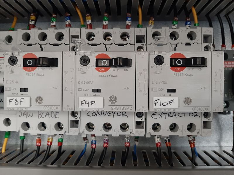
This tutorial will walk you through how to read a motor plate and set the Motor Overload Relays to the information you gain from the motor plate.
Introduction
Étape 1 - Read the Motor Plate
In order to read the motor plate we need to know 3 pieces of information
- Whether the motor is wired in star or delta
- The frequency at which the motor is running
- The voltage at which the motor is running
Whether the motor is wired in star or delta depends on the application. Refer to the electrical diagrams to find out which it is. For example, the saw blade motor is wired in star, whereas most extractor motors are wired in delta.
The UK standard for a three phase electrical supply is 415v at 50Hz. Unless the supply to a motor runs through an inverter (i.e the spindles) this is also the standard for our machines.
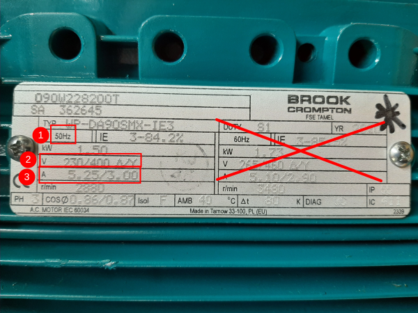
Using the picture on the right as an example, we know the motor will be running at 50Hz (1) so we can disregard the information on the right of the plate as this provides figures for a 60Hz supply.
Looking at the box numbered (2) we can work out that this motor would be wired in delta if it were running on a single phase 230v supply. However, we know that this is a three phase supply and will be wired in star. So when we move on to the box numbered (3) we will be looking at the number on the right hand side of the slash.
Therefore, this particular motor would need an Overload Relay set to 3.00A.
Étape 2 - Setting the Motor Overload Relay
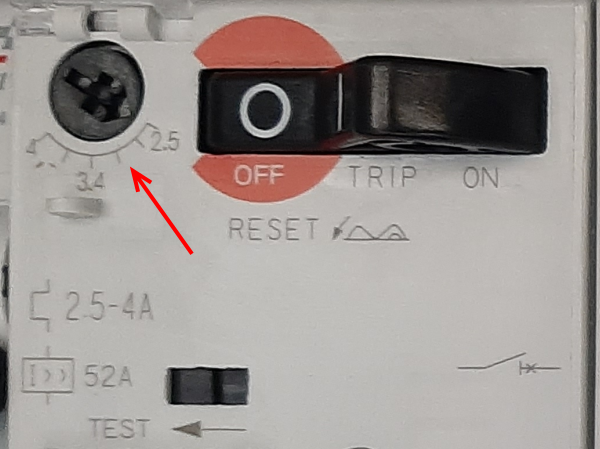
Using the example motor from the above step, this Overload Relay would need to be set to 3.00A.
- Lift the plastic cover that covers the dial to the left hand side of the rocker switch.
- Using a small screwdriver, turn the dial to the required amperage (or as close as possible!) It is better to set the dial slightly over than slightly under if you cannot get it exact.
- Replace cover
Draft


 Français
 English
 Deutsch
 Español
 Italiano
 Português