| [version en cours de rédaction] | [version en cours de rédaction] |
| Ligne 74 : | Ligne 74 : | ||
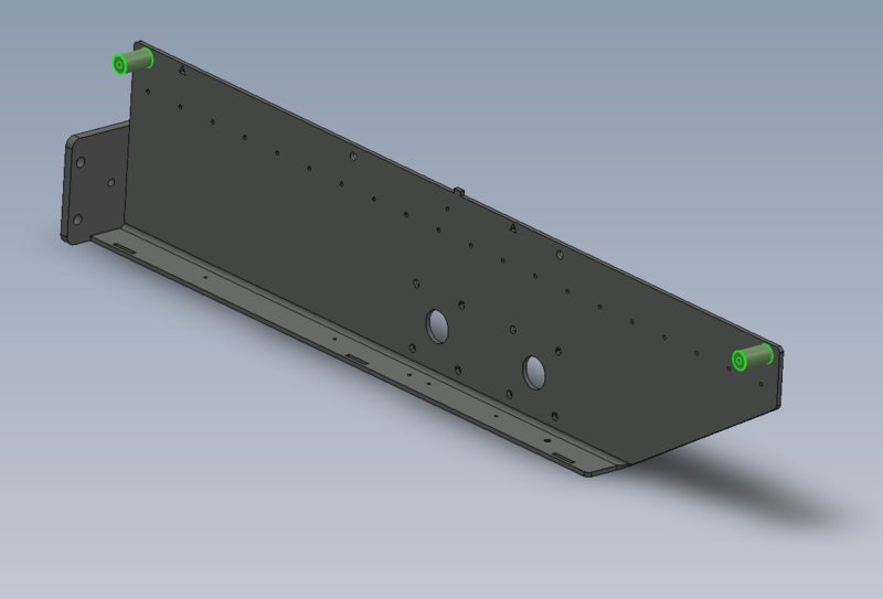
|Step_Content=<translate>2 off per arm | |Step_Content=<translate>2 off per arm | ||
| − | + | Fix using M8 x 20 button head socket</translate> | |
| − | + | |Step_Picture_00=R0015095_Bench_Assemble_Infeed_Support_Arms_Screenshot_2023-07-31_104705.png | |
| − | |||
| − | | | ||
| − | |||
| − | |||
| − | |||
}} | }} | ||
{{Notes}} | {{Notes}} | ||
Version du 31 juillet 2023 à 10:47
Instructions to bench assemble infeed support arms
Introduction
Tools Required
Standard hex key set
Standard tap sete
Setting jigs
Parts required
B0001170 Spacer 180 off
B0001155 open rail 18 off
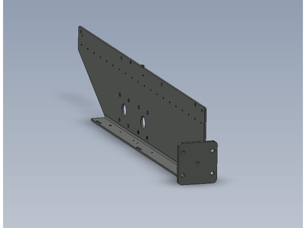
D0015553 Transfer Support arm R/H (right to left machine ) OR D0015552 Transfer Support Arm L/H ( Left to Right machine)
D0015554 x 18Étape 1 - Unless otherwise stated
Use Loctite 243 on all fasteners
Use Loctite 572 on all threaded pneumatic connections
Pen mark all bolts to show finalised
Étape 2 - Hand of parts issued determines handing.
Steps shown below will show location and position of parts and procedure for fitting , not orientation
Étape 4 - Align spacers and fit setting jigs
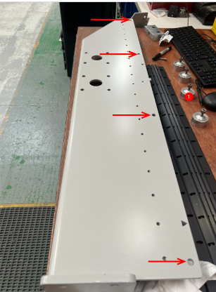
1 Mount 4 off setting jigs to arm on the indicated points
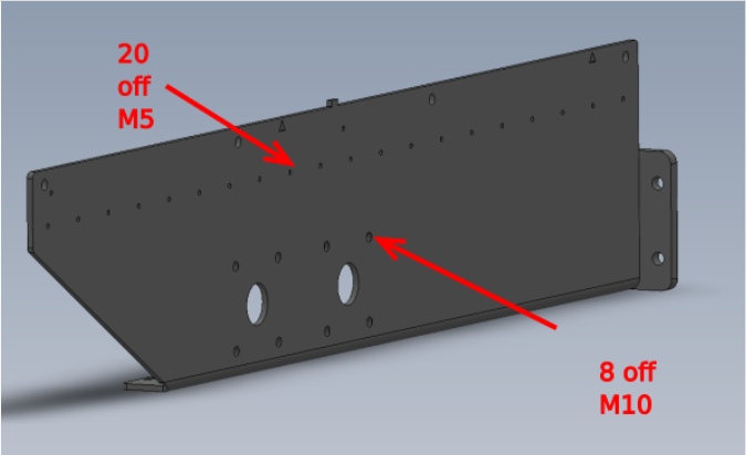
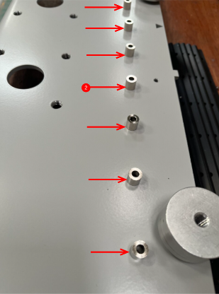
2 align spacers over all m5 holes
Étape 5 - Fix Rail to arm
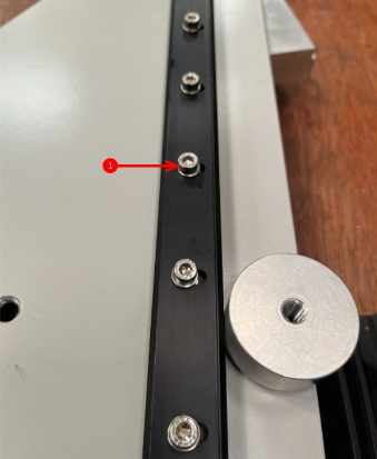
1 Use M5 x 25 socket cap and A form washer with loctite 243 to fix rail to arm
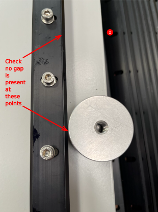
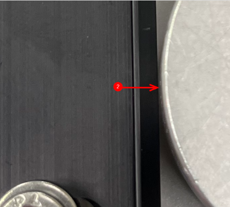
2 Ensure rail touching setting jig as indicated and two rails are pushed completely together
Draft


 Français
 English
 Deutsch
 Español
 Italiano
 Português