| [version en cours de rédaction] | [version en cours de rédaction] |
| (2 révisions intermédiaires par le même utilisateur non affichées) | |||
| Ligne 5 : | Ligne 5 : | ||
|Duration=3 | |Duration=3 | ||
|Duration-type=day(s) | |Duration-type=day(s) | ||
| − | |Tags=6.5m, Extension, Upgrade | + | |Tags=6.5m, Extension, Upgrade, 6.5 |
}} | }} | ||
{{Introduction | {{Introduction | ||
| Ligne 125 : | Ligne 125 : | ||
<br /></translate> | <br /></translate> | ||
|Step_Picture_00=Flowline_6_to_6o5m_Extension_16.jpg | |Step_Picture_00=Flowline_6_to_6o5m_Extension_16.jpg | ||
| + | }} | ||
| + | {{Tuto Step | ||
| + | |Step_Title=<translate>Re-fit X and SX axis Carriages</translate> | ||
| + | |Step_Content=<translate>Fit both X and SX carriages onto new Hepco rails and adjust eccentric journals to fit, then tighten. Once tightened, remove carriages, fit journal covers and then slide back on the Hepco rails. | ||
| + | |||
| + | |||
| + | Now connect all cable and air pipes to carriage, and make sure both limit blocks are fitted to either axis (pics)</translate> | ||
| + | |Step_Picture_00=Flowline_6_to_6o5m_Extension_10.jpg | ||
| + | |Step_Picture_01=Flowline_6_to_6o5m_Extension_11.jpg | ||
}} | }} | ||
{{Tuto Step | {{Tuto Step | ||
| Ligne 174 : | Ligne 183 : | ||
Set 'datumtomat' parameter, then check /correct scaling and datum figures on both axis.</translate> | Set 'datumtomat' parameter, then check /correct scaling and datum figures on both axis.</translate> | ||
|Step_Picture_00=Flowline_6_to_6o5m_Extension_21.jpg | |Step_Picture_00=Flowline_6_to_6o5m_Extension_21.jpg | ||
| − | |||
| − | |||
| − | |||
| − | |||
| − | |||
| − | |||
| − | |||
| − | |||
| − | |||
}} | }} | ||
{{Notes}} | {{Notes}} | ||
| Ligne 191 : | Ligne 191 : | ||
}} | }} | ||
{{Tuto Status | {{Tuto Status | ||
| − | |Complete= | + | |Complete=Published |
}} | }} | ||
Version actuelle datée du 30 mars 2022 à 08:36
Procedure for increasing flowline capacity from 6 to 6.5m

Difficulté
Difficile
Durée
3 jour(s)
Sommaire
- 1 Introduction
- 2 Étape 1 - Remove Guarding/Extraction
- 3 Étape 2 - Removing carriages and replacing Journals
- 4 Étape 3 - Remove Hepco rails
- 5 Étape 4 - Prepare Hepco support base surface
- 6 Étape 5 - Drilling Extension Pieces
- 7 Étape 6 - Fit Extensions
- 8 Étape 7 - Fit 6.5m Hepco Rail
- 9 Étape 8 - Final Bracket Fix
- 10 Étape 9 - Extend Cables and pipes
- 11 Étape 10 - Re-fit X and SX axis Carriages
- 12 Étape 11 - Moving Datum bracket
- 13 Étape 12 - Moving Rear guard mounting bracket
- 14 Étape 13 - Fit extra Transfer support block
- 15 Étape 14 - Re-fit Guarding
- 16 Étape 15 - Fit profile support plate
- 17 Étape 16 - Extend Extraction
- 18 Étape 17 - Set up Parametres
- 19 Commentaires
Introduction
This procedure describes how to upgrade a flowline to increase the standard capacity from 6.0m to 6.5m.
The procedure involves extending the machining centre outfeed travel and saw infeed travel base to 6.0m to cope with a longer rail on each side. These are generally supplied as a new part.
Other ancillary parts that will need extending
- Cables
- Energy Chains
Étape 1 - Remove Guarding/Extraction
Isolate power to extraction and then disconnect the cable from extraction motor. Remove floor bolt nuts from the extraction unit feet, and separate the ducting so that the unit can be moved.
Once moved, disconnect all guarding to the far end of multi outfeed and saw infeed (pictured).
Detach Outfeed beam sensor with the bracket so that the rear guarding support box section can be removed.

Étape 2 - Removing carriages and replacing Journals
Remove both X and SX rear limit stops blocks, then disconnect all energy chain cables and air pipes at the carriage end.
Unclip the energy chain and remove both carriages from the axis.
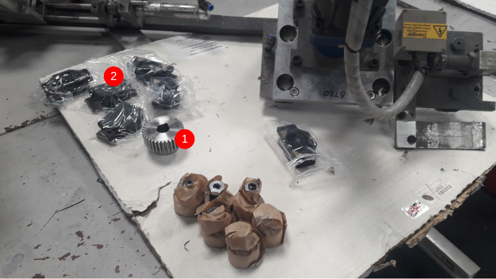
On a bench, remove Gearbox/motor assembly's and replace the pinion gears (item 1), adding a small amount of Loctite on grubscrew when re-tightening.
Now remove all x6 journals and x6 covers from carriage and disregard.
Then Fit:
x3 Concentric Journals - These must be fitted on the TEETH SIDE of the Hepco rail.
x3 Eccentric Journals - Fit on the opposite side and LEAVE LOOSE for now.
Leave the x6 Journal covers off for now (item 2).
Étape 3 - Remove Hepco rails
Detach both Hepco rails by removing the 6mm caphead bolts (pictured).
Once rails are removed, they can be separated into shorter lengths by knocking out the dowel pins towards the centre sections.

Étape 4 - Prepare Hepco support base surface
Clean and remove any dirt/grease/imperfections on the box section ready the the new rails.
If any of the tapped holes are compromised, re-tap 6mm.

Étape 5 - Drilling Extension Pieces
Offer extension piece (box section) up to existing axis beam and clamp on using large G clamps and fixing angle **(*pic required) **
Mark holes in both pieces then drill/ tap 6mm.

Étape 6 - Fit Extensions
Fit angle bracket to extension box sections using 6mm capheads....and locknuts where accessible for extra security (pic).
Do not fit to mainframe yet....only use G clamps until Hepco rail is attached.

Étape 7 - Fit 6.5m Hepco Rail
Fit new Hepco rail using 6mm capheads whilst extension piece is clamped onto frame (pic).
Each new Hepco rail will require pinning together, making sure the joints are as seamless as possible to allow gripper/pusher carriages to pass over freely.
Once rails are fitted to main frames, new holes can be marked/drilled/tapped 6mm (pic) on the extension pieces and secured.

Étape 8 - Final Bracket Fix
Now the last fixes between the angle and main frames can be drilled/tapped and secured.

Étape 9 - Extend Cables and pipes
All Energy chain cable and pipes, as well as the energy chain itself, will need to be 500mm longer.
If there's enough slack on current cables (and are in good condition), then extend and re-route. All other cables and air pipes will need replacing.
The energy chain itself will require extra links fitted (500mm).
Other cables that will need to be extended/or replaced:
Extraction power cable.
SX axis datum switch cable.
Outfeed beam cable.

Étape 10 - Re-fit X and SX axis Carriages
Fit both X and SX carriages onto new Hepco rails and adjust eccentric journals to fit, then tighten. Once tightened, remove carriages, fit journal covers and then slide back on the Hepco rails.
Now connect all cable and air pipes to carriage, and make sure both limit blocks are fitted to either axis (pics)


Étape 11 - Moving Datum bracket
Bracket (pic) that's holding the SX axis datum switch will need to be moved 500mm towards the outfeed end and re-drilled-tapped 6mm.

Étape 12 - Moving Rear guard mounting bracket
Rear guard mounting bracket will then need moving 500mm towards outfeed end.
New holes will require drilling/tapping on the saw infeed side to accommodate the other end of the rear guarding when ready to fit.

Étape 13 - Fit extra Transfer support block
Fit extra support block towards outfeed end o X axis. Make sure its sitting completely flush with the top of the clacker housing trays (pic).

Étape 14 - Re-fit Guarding
Fit guarding, including all required extension pieces.
Re-fit Outfeed beam sensor and set up to reflector.

Étape 15 - Fit profile support plate
Mark/drill and tap holes for rear profile support plate.
Make sure this sits just below multi outfeed level so profile transition is smooth. The support plate has slots if adjustment is required.

Étape 16 - Extend Extraction
Extend extraction ducting and refit unit. Re-wire motor and test direction.

Étape 17 - Set up Parametres
Update 'InfeedLength' Param to 6500. Test both X and SX axis inputs on the io screen.
Test travel of 6.5m profile from multi all the way across to the saw.
Set 'datumtomat' parameter, then check /correct scaling and datum figures on both axis.

Published
 Français
 English
 Deutsch
 Español
 Italiano
 Português