| [version en cours de rédaction] | [version en cours de rédaction] |
(Page créée avec « {{Tuto Details |Description=<translate>The design of the ZX4 Infeed Table was such that the first roller was located by a single block, of which was attached to the first... ») |
|||
| (Une révision intermédiaire par le même utilisateur non affichée) | |||
| Ligne 1 : | Ligne 1 : | ||
{{Tuto Details | {{Tuto Details | ||
| + | |Main_Picture=ZX4_Infeed_Roller_Reinforcement_Annotation_2020-03-31_142909.jpg | ||
| + | |Main_Picture_annotation={"version":"2.4.6","objects":[{"type":"image","version":"2.4.6","originX":"left","originY":"top","left":-216,"top":-230,"width":534,"height":417,"fill":"rgb(0,0,0)","stroke":null,"strokeWidth":0,"strokeDashArray":null,"strokeLineCap":"butt","strokeDashOffset":0,"strokeLineJoin":"miter","strokeMiterLimit":4,"scaleX":1.85,"scaleY":1.85,"angle":0,"flipX":false,"flipY":false,"opacity":1,"shadow":null,"visible":true,"clipTo":null,"backgroundColor":"","fillRule":"nonzero","paintFirst":"fill","globalCompositeOperation":"source-over","transformMatrix":null,"skewX":0,"skewY":0,"crossOrigin":"","cropX":0,"cropY":0,"src":"https://stuga.dokit.app/images/9/91/ZX4_Infeed_Roller_Reinforcement_Annotation_2020-03-31_142909.jpg","filters":[]}],"height":449.74093264248705,"width":600} | ||
|Description=<translate>The design of the ZX4 Infeed Table was such that the first roller was located by a single block, of which was attached to the first arm by 2 bolts and a single dowel. The clearance on the two bolt holes meant that the block could rotate slightly around the dowel, resulting in the roller having a large potential deflection when load was put on it.</translate> | |Description=<translate>The design of the ZX4 Infeed Table was such that the first roller was located by a single block, of which was attached to the first arm by 2 bolts and a single dowel. The clearance on the two bolt holes meant that the block could rotate slightly around the dowel, resulting in the roller having a large potential deflection when load was put on it.</translate> | ||
|Categories=Maintenance | |Categories=Maintenance | ||
| Ligne 13 : | Ligne 15 : | ||
{{EPI}} | {{EPI}} | ||
{{Tuto Step | {{Tuto Step | ||
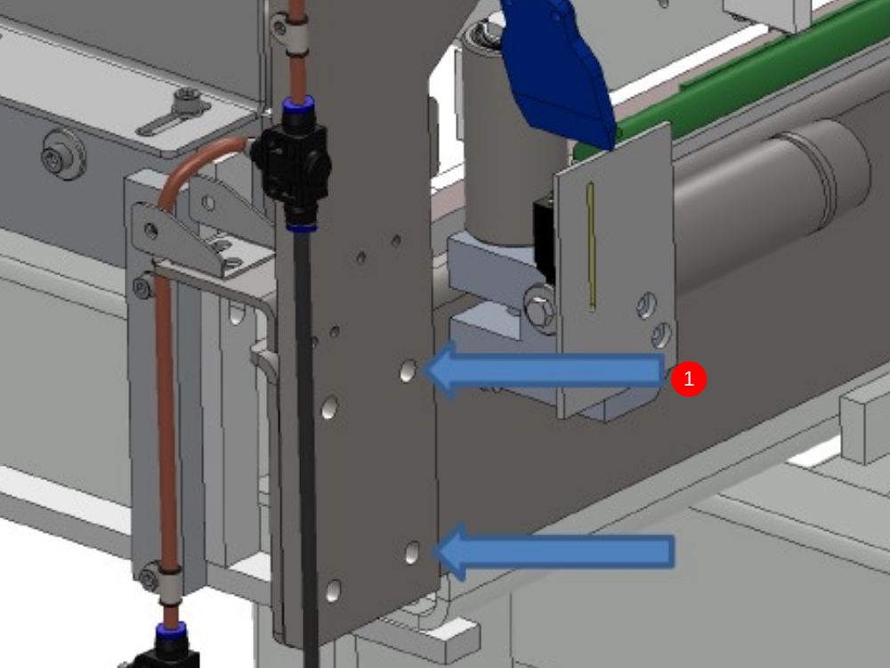
| − | |Step_Title=<translate></translate> | + | |Step_Title=<translate>Remove the 2x M8 bolts as shown.</translate> |
| + | |Step_Content=<translate></translate> | ||
| + | |Step_Picture_00=ZX4_Infeed_Roller_Reinforcement_Annotation_2020-03-31_142855.jpg | ||
| + | |Step_Picture_00_annotation={"version":"2.4.6","objects":[{"type":"image","version":"2.4.6","originX":"left","originY":"top","left":-24,"top":-20,"width":532,"height":416,"fill":"rgb(0,0,0)","stroke":null,"strokeWidth":0,"strokeDashArray":null,"strokeLineCap":"butt","strokeDashOffset":0,"strokeLineJoin":"miter","strokeMiterLimit":4,"scaleX":1.29,"scaleY":1.29,"angle":0,"flipX":false,"flipY":false,"opacity":1,"shadow":null,"visible":true,"clipTo":null,"backgroundColor":"","fillRule":"nonzero","paintFirst":"fill","globalCompositeOperation":"source-over","transformMatrix":null,"skewX":0,"skewY":0,"crossOrigin":"","cropX":0,"cropY":0,"src":"https://stuga.dokit.app/images/1/19/ZX4_Infeed_Roller_Reinforcement_Annotation_2020-03-31_142855.jpg","filters":[]},{"type":"wfnumberedbullet","version":"2.4.6","originX":"left","originY":"top","left":452,"top":242.95,"width":25,"height":25,"fill":"rgb(0,0,0)","stroke":"#FF0000","strokeWidth":0,"strokeDashArray":null,"strokeLineCap":"butt","strokeDashOffset":0,"strokeLineJoin":"miter","strokeMiterLimit":4,"scaleX":1,"scaleY":1,"angle":0,"flipX":false,"flipY":false,"opacity":1,"shadow":null,"visible":true,"clipTo":null,"backgroundColor":"","fillRule":"nonzero","paintFirst":"fill","globalCompositeOperation":"source-over","transformMatrix":null,"skewX":0,"skewY":0,"objects":[{"type":"circle","version":"2.4.6","originX":"center","originY":"center","left":0,"top":0,"width":24,"height":24,"fill":"#FF0000","stroke":null,"strokeWidth":1,"strokeDashArray":null,"strokeLineCap":"butt","strokeDashOffset":0,"strokeLineJoin":"miter","strokeMiterLimit":4,"scaleX":1,"scaleY":1,"angle":0,"flipX":false,"flipY":false,"opacity":1,"shadow":null,"visible":true,"clipTo":null,"backgroundColor":"","fillRule":"nonzero","paintFirst":"fill","globalCompositeOperation":"source-over","transformMatrix":null,"skewX":0,"skewY":0,"radius":12,"startAngle":0,"endAngle":6.283185307179586},{"type":"text","version":"2.4.6","originX":"center","originY":"center","left":0,"top":0,"width":7.79,"height":15.82,"fill":"rgba(255,255,255,255)","stroke":null,"strokeWidth":1,"strokeDashArray":null,"strokeLineCap":"butt","strokeDashOffset":0,"strokeLineJoin":"miter","strokeMiterLimit":4,"scaleX":1,"scaleY":1,"angle":0,"flipX":false,"flipY":false,"opacity":1,"shadow":null,"visible":true,"clipTo":null,"backgroundColor":"","fillRule":"nonzero","paintFirst":"fill","globalCompositeOperation":"source-over","transformMatrix":null,"skewX":0,"skewY":0,"text":"1","fontSize":14,"fontWeight":"normal","fontFamily":"arial","fontStyle":"normal","lineHeight":1.16,"underline":false,"overline":false,"linethrough":false,"textAlign":"left","textBackgroundColor":"","charSpacing":0,"styles":{} }],"number":1}],"height":450.18007202881154,"width":600} | ||
| + | }} | ||
| + | {{Tuto Step | ||
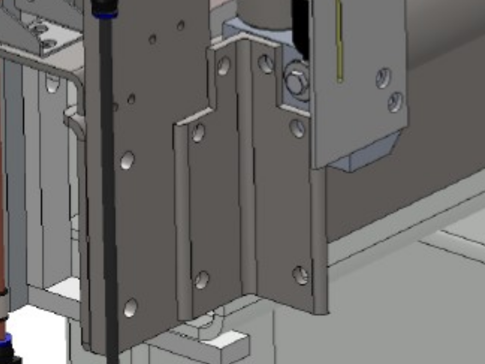
| + | |Step_Title=<translate>Align Infeed roller block</translate> | ||
| + | |Step_Content=<translate>Align the infeed roller block so that it is square (check the roller with a straight edge against the other rollers). Fit the bracket using the 2 off M8 x 25 Bolts. Mark through the clearance holes on the bracket onto the roller block.</translate> | ||
| + | |Step_Picture_00=ZX4_Infeed_Roller_Reinforcement_Annotation_2020-03-31_142909.jpg | ||
| + | }} | ||
| + | {{Tuto Step | ||
| + | |Step_Title=<translate>Remove the new strengthening bracket.</translate> | ||
| + | |Step_Content=<translate></translate> | ||
| + | }} | ||
| + | {{Tuto Step | ||
| + | |Step_Title=<translate>Drill and tap into the infeed roller block</translate> | ||
| + | |Step_Content=<translate>Reinstall strengthening bracket with 2x M8 x 16 Bolts (F0000023) into the infeed roller block, and the 2x M8 x 25 Bolts (F0000025) into the infeed arm.</translate> | ||
| + | }} | ||
| + | {{Tuto Step | ||
| + | |Step_Title=<translate>Recheck alignment of infeed roller</translate> | ||
|Step_Content=<translate></translate> | |Step_Content=<translate></translate> | ||
}} | }} | ||
{{Notes}} | {{Notes}} | ||
{{PageLang | {{PageLang | ||
| + | |Language=en | ||
|SourceLanguage=none | |SourceLanguage=none | ||
|IsTranslation=0 | |IsTranslation=0 | ||
| − | |||
}} | }} | ||
{{Tuto Status | {{Tuto Status | ||
|Complete=Draft | |Complete=Draft | ||
}} | }} | ||
Version actuelle datée du 31 mars 2020 à 15:34
The design of the ZX4 Infeed Table was such that the first roller was located by a single block, of which was attached to the first arm by 2 bolts and a single dowel. The clearance on the two bolt holes meant that the block could rotate slightly around the dowel, resulting in the roller having a large potential deflection when load was put on it.

Difficulté
Moyen
Durée
2 heure(s)
Introduction
A plate has been designed to strengthen the installation of the first roller.
Étape 1 - Remove the 2x M8 bolts as shown.
Étape 2 - Align Infeed roller block
Align the infeed roller block so that it is square (check the roller with a straight edge against the other rollers). Fit the bracket using the 2 off M8 x 25 Bolts. Mark through the clearance holes on the bracket onto the roller block.

Étape 3 - Remove the new strengthening bracket.
Étape 4 - Drill and tap into the infeed roller block
Reinstall strengthening bracket with 2x M8 x 16 Bolts (F0000023) into the infeed roller block, and the 2x M8 x 25 Bolts (F0000025) into the infeed arm.
Étape 5 - Recheck alignment of infeed roller
Draft
 Français
 English
 Deutsch
 Español
 Italiano
 Português