| [version en cours de rédaction] | [version en cours de rédaction] |
(Page créée avec « {{Tuto Details |Description=<translate>This document records the result of the process carried out today to “normalise” the design and part notation for the PCBs that... ») |
|||
| Ligne 4 : | Ligne 4 : | ||
|Tags=TB0408, Stuga, PCB, Normalisation | |Tags=TB0408, Stuga, PCB, Normalisation | ||
}} | }} | ||
| − | <translate>= Technical Bulletin = | + | <translate>=Technical Bulletin= |
{| class="wikitable" border="1" cellspacing="0" cellpadding="0" width="673" | {| class="wikitable" border="1" cellspacing="0" cellpadding="0" width="673" | ||
| width="118" valign="top" |'''TB Number:''' | | width="118" valign="top" |'''TB Number:''' | ||
| Ligne 15 : | Ligne 15 : | ||
| width="555" valign="top" |All | | width="555" valign="top" |All | ||
|- | |- | ||
| − | | width="118" valign="top" |'''Date:''' | + | | width="118" valign="top" |'''Date:''' |
| width="555" valign="top" |27/06/18 | | width="555" valign="top" |27/06/18 | ||
|- | |- | ||
| width="118" valign="top" |'''Circulate to:''' | | width="118" valign="top" |'''Circulate to:''' | ||
| − | | width="555" valign="top" |Stores; Service; Suppliers | + | | width="555" valign="top" |Stores; Service; Suppliers |
|- | |- | ||
| width="118" valign="top" |'''Title:''' | | width="118" valign="top" |'''Title:''' | ||
| Ligne 30 : | Ligne 30 : | ||
|} | |} | ||
| − | == Summary == | + | ==Summary== |
This document records the result of the process carried out today to “normalise” the design and part notation for the PCBs that Stuga outsource. This follows confusion of poor naming and a lack of part numbers. | This document records the result of the process carried out today to “normalise” the design and part notation for the PCBs that Stuga outsource. This follows confusion of poor naming and a lack of part numbers. | ||
| Ligne 44 : | Ligne 44 : | ||
{{#annotatedImageLight:Fichier:TB0408 Stuga PCB Design Normalisation Image.png|0=143px|hash=|jsondata=|mediaClass=Image|type=frameless|align=right|src=https://stuga.dokit.app/images/c/c6/TB0408_Stuga_PCB_Design_Normalisation_Image.png|href=./Fichier:TB0408 Stuga PCB Design Normalisation Image.png|resource=./Fichier:TB0408 Stuga PCB Design Normalisation Image.png|caption=|size=143px}} | {{#annotatedImageLight:Fichier:TB0408 Stuga PCB Design Normalisation Image.png|0=143px|hash=|jsondata=|mediaClass=Image|type=frameless|align=right|src=https://stuga.dokit.app/images/c/c6/TB0408_Stuga_PCB_Design_Normalisation_Image.png|href=./Fichier:TB0408 Stuga PCB Design Normalisation Image.png|resource=./Fichier:TB0408 Stuga PCB Design Normalisation Image.png|caption=|size=143px}} | ||
| − | == C0000269 Spindle Control ZX Mk1-3 == | + | ==C0000269 Spindle Control ZX Mk1-3== |
· This board replaces the older C0269 that was sourced from Smartdrive before they went out of business. | · This board replaces the older C0269 that was sourced from Smartdrive before they went out of business. | ||
| Ligne 51 : | Ligne 51 : | ||
<br />{{#annotatedImageLight:Fichier:TB0408 Stuga PCB Design Normalisation Image1.png|0=231px|hash=|jsondata=|mediaClass=Image|type=frameless|align=right|src=https://stuga.dokit.app/images/7/7c/TB0408_Stuga_PCB_Design_Normalisation_Image1.png|href=./Fichier:TB0408 Stuga PCB Design Normalisation Image1.png|resource=./Fichier:TB0408 Stuga PCB Design Normalisation Image1.png|caption=|size=231px}} | <br />{{#annotatedImageLight:Fichier:TB0408 Stuga PCB Design Normalisation Image1.png|0=231px|hash=|jsondata=|mediaClass=Image|type=frameless|align=right|src=https://stuga.dokit.app/images/7/7c/TB0408_Stuga_PCB_Design_Normalisation_Image1.png|href=./Fichier:TB0408 Stuga PCB Design Normalisation Image1.png|resource=./Fichier:TB0408 Stuga PCB Design Normalisation Image1.png|caption=|size=231px}} | ||
| − | == C0000436 Spindle Control ZX Mk4 == | + | ==C0000436 Spindle Control ZX Mk4== |
· There is more confusion generated by another spindle card with taller relays, labelled C0000436. | · There is more confusion generated by another spindle card with taller relays, labelled C0000436. | ||
| Ligne 60 : | Ligne 60 : | ||
| − | <br /> | + | <br />{{#annotatedImageLight:Fichier:TB0408 Stuga PCB Design Normalisation Image2.png|0=150px|hash=|jsondata=|mediaClass=Image|type=frameless|align=right|src=https://stuga.dokit.app/images/9/9b/TB0408_Stuga_PCB_Design_Normalisation_Image2.png|href=./Fichier:TB0408 Stuga PCB Design Normalisation Image2.png|resource=./Fichier:TB0408 Stuga PCB Design Normalisation Image2.png|caption=|size=150px}} |
| − | + | ==C0001137 3 Phase Current Monitor== | |
| − | == C0001137 3 Phase Current Monitor == | ||
· Used to monitor the current output on 3 phases and provide 3 channel voltage output | · Used to monitor the current output on 3 phases and provide 3 channel voltage output | ||
| Ligne 70 : | Ligne 69 : | ||
| − | == C0001163 RS Automation Encoder Interface == | + | ==C0001163 RS Automation Encoder Interface== |
{{#annotatedImageLight:Fichier:TB0408 Stuga PCB Design Normalisation Image3.png|0=117px|hash=|jsondata=|mediaClass=Image|type=frameless|align=right|src=https://stuga.dokit.app/images/a/a9/TB0408_Stuga_PCB_Design_Normalisation_Image3.png|href=./Fichier:TB0408 Stuga PCB Design Normalisation Image3.png|resource=./Fichier:TB0408 Stuga PCB Design Normalisation Image3.png|caption=|size=117px}}· Used to convert the bare ended cable wires into a socket for a standard Firewire lead for final connection to encoder input on | {{#annotatedImageLight:Fichier:TB0408 Stuga PCB Design Normalisation Image3.png|0=117px|hash=|jsondata=|mediaClass=Image|type=frameless|align=right|src=https://stuga.dokit.app/images/a/a9/TB0408_Stuga_PCB_Design_Normalisation_Image3.png|href=./Fichier:TB0408 Stuga PCB Design Normalisation Image3.png|resource=./Fichier:TB0408 Stuga PCB Design Normalisation Image3.png|caption=|size=117px}}· Used to convert the bare ended cable wires into a socket for a standard Firewire lead for final connection to encoder input on | ||
| Ligne 82 : | Ligne 81 : | ||
<br /> | <br /> | ||
| − | == C0001206 Smartdrive Replacement Breakout == | + | ==C0001206 Smartdrive Replacement Breakout== |
{{#annotatedImageLight:Fichier:TB0408 Stuga PCB Design Normalisation Image4.png|0=213px|hash=|jsondata=|mediaClass=Image|type=frameless|align=right|src=https://stuga.dokit.app/images/c/c6/TB0408_Stuga_PCB_Design_Normalisation_Image4.png|href=./Fichier:TB0408 Stuga PCB Design Normalisation Image4.png|resource=./Fichier:TB0408 Stuga PCB Design Normalisation Image4.png|caption=|size=213px}}· This board replaces the older C0000157 that was sourced from Smartdrive before they went out of business. | {{#annotatedImageLight:Fichier:TB0408 Stuga PCB Design Normalisation Image4.png|0=213px|hash=|jsondata=|mediaClass=Image|type=frameless|align=right|src=https://stuga.dokit.app/images/c/c6/TB0408_Stuga_PCB_Design_Normalisation_Image4.png|href=./Fichier:TB0408 Stuga PCB Design Normalisation Image4.png|resource=./Fichier:TB0408 Stuga PCB Design Normalisation Image4.png|caption=|size=213px}}· This board replaces the older C0000157 that was sourced from Smartdrive before they went out of business. | ||
| Ligne 99 : | Ligne 98 : | ||
<br /> | <br /> | ||
| − | == C0001180 RS Automation All-in-one Interface == | + | ==C0001180 RS Automation All-in-one Interface== |
| + | |||
| Ligne 106 : | Ligne 106 : | ||
· As of June 2018, main 50 way connector is on August delivery, so full replacement project on hold</translate> | · As of June 2018, main 50 way connector is on August delivery, so full replacement project on hold</translate> | ||
{{PageLang | {{PageLang | ||
| + | |Language=en | ||
|SourceLanguage=none | |SourceLanguage=none | ||
|IsTranslation=0 | |IsTranslation=0 | ||
| − | |||
}} | }} | ||
{{AddComments}} | {{AddComments}} | ||
Version actuelle datée du 14 mars 2020 à 13:08
This document records the result of the process carried out today to “normalise” the design and part notation for the PCBs that Stuga outsource. This follows confusion of poor naming and a lack of part numbers.
Sommaire
Technical Bulletin
| TB Number: | 408-2 |
| Originator: | Gareth Green |
| Machine: | All |
| Date: | 27/06/18 |
| Circulate to: | Stores; Service; Suppliers |
| Title: | Stuga PCB Design Normalisation |
| Version 2 | Error made with C0000436 card, should have been numbered C0000269. Now corrected
C0000436 is a card in its own right, but rarely used. |
Summary
This document records the result of the process carried out today to “normalise” the design and part notation for the PCBs that Stuga outsource. This follows confusion of poor naming and a lack of part numbers.
· All PCB assemblies (BOM) have been renumbered (if necessary) to start with a ‘C’
· All PCB assemblies (BOM) renamed to start “PCB Assembly” and renamed to make more sense and to remove mistakes and confusion
· All PCB board artwork renumbered to have the same number as the parent assembly with “–PCB” on the end
· All PCB board artwork renamed to start “PCB:” and the same name as the assembly
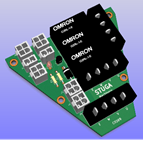
C0000269 Spindle Control ZX Mk1-3
· This board replaces the older C0269 that was sourced from Smartdrive before they went out of business.
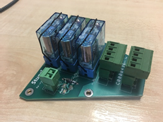
C0000436 Spindle Control ZX Mk4
· There is more confusion generated by another spindle card with taller relays, labelled C0000436.
· This card is used on ZX4 Mk4 machines with EtherCAT system and was later replaced by a simple Schrack relay and terminal blocks
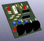
C0001137 3 Phase Current Monitor
· Used to monitor the current output on 3 phases and provide 3 channel voltage output
· This board will not be required in future when the new inverter is implemented
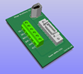
C0001163 RS Automation Encoder Interface
· Used to convert the bare ended cable wires into a socket for a standard Firewire lead for final connection to encoder input on
RS Automation Drive.
· 25 way high density D socket was a trial to maybe utilise the connectors already in existence on older machines,
but in practice it is easier to cut the plug off and use bare ended cores in the screw terminals, therefore this connector is not fitted
· Only needs the firewire and the 6 way Screw termination
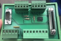
C0001206 Smartdrive Replacement Breakout
· This board replaces the older C0000157 that was sourced from Smartdrive before they went out of business.
· Used to breakout the RS Automation and Samsung drive 50 way connector to the drive connections
· This was previously numbered
o R0010304 for the assembly
o E0001206 for the PCB
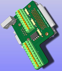
C0001180 RS Automation All-in-one Interface
· This is a new design to replace C0001163 and C0001206 along with a 50way-50 way lead into one direct plug in card
· This saves on components, mounting space and wiring
· As of June 2018, main 50 way connector is on August delivery, so full replacement project on hold
Draft
 Français
 English
 Deutsch
 Español
 Italiano
 Português