| [version en cours de rédaction] | [version en cours de rédaction] |
(Page créée avec « {{Tuto Details |Description=<translate>This module guides the engineer on how to correctly adjust the centralising mechanism on Stuga saws. The engineer will need a reas... ») |
|||
| (2 révisions intermédiaires par le même utilisateur non affichées) | |||
| Ligne 1 : | Ligne 1 : | ||
{{Tuto Details | {{Tuto Details | ||
| + | |Main_Picture=TM016_Arrow_Head_Adjustment_on_Saw_image8.jpg | ||
| + | |Main_Picture_annotation={"version":"2.4.6","objects":[{"type":"image","version":"2.4.6","originX":"left","originY":"top","left":53,"top":5,"width":397,"height":352,"fill":"rgb(0,0,0)","stroke":null,"strokeWidth":0,"strokeDashArray":null,"strokeLineCap":"butt","strokeDashOffset":0,"strokeLineJoin":"miter","strokeMiterLimit":4,"scaleX":1.23,"scaleY":1.23,"angle":0,"flipX":false,"flipY":false,"opacity":1,"shadow":null,"visible":true,"clipTo":null,"backgroundColor":"","fillRule":"nonzero","paintFirst":"fill","globalCompositeOperation":"source-over","transformMatrix":null,"skewX":0,"skewY":0,"crossOrigin":"","cropX":0,"cropY":0,"src":"https://stuga.dokit.app/images/8/81/TM016_Arrow_Head_Adjustment_on_Saw_image8.jpg","filters":[]}],"height":449.80132450331126,"width":600} | ||
|Description=<translate>This module guides the engineer on how to correctly adjust the centralising mechanism on Stuga saws. | |Description=<translate>This module guides the engineer on how to correctly adjust the centralising mechanism on Stuga saws. | ||
The engineer will need a reasonable mechanical knowledge, and a working knowledge of the operation of the machine.</translate> | The engineer will need a reasonable mechanical knowledge, and a working knowledge of the operation of the machine.</translate> | ||
| Ligne 9 : | Ligne 11 : | ||
}} | }} | ||
{{Introduction | {{Introduction | ||
| − | |Introduction=<translate>When in arrow head or centralising mode, the pivot point of the saw blade is moved from the bladetofence position to the central position of the current section. The mechanism that achieves this allows for any width of profile from 45 mm to 130 mm. If the arrow head position is not central to the profile, the centraliser position may need to be adjusted</translate> | + | |Introduction=<translate>When in arrow head or centralising mode, the pivot point of the saw blade is moved from the bladetofence position to the central position of the current section. The mechanism that achieves this allows for any width of profile from 45 mm to 130 mm. If the arrow head position is not central to the profile, the centraliser position may need to be adjusted |
| + | |||
| + | {{Pin|...In our experience, the most likely cause of this problem is either an offcut not allowing the centraliser to close fully, or an issue with the symmetry of the profile}}<br /></translate> | ||
| + | }} | ||
| + | {{Materials | ||
| + | |ItemList={{ItemList | ||
| + | |Item=150mm Rule | ||
| + | }}{{ItemList | ||
| + | |Item=Spanner 17mm | ||
| + | }}{{ItemList | ||
| + | |Item=Spanner 8mm | ||
| + | }}{{ItemList | ||
| + | |Item=D0001387 Stuga 45 Degree Setting Block | ||
| + | }} | ||
}} | }} | ||
| − | |||
{{EPI}} | {{EPI}} | ||
{{Tuto Step | {{Tuto Step | ||
| − | |Step_Title=<translate></translate> | + | |Step_Title=<translate>Check Centraliser Closes fully</translate> |
| − | |Step_Content=<translate></translate> | + | |Step_Content=<translate>To check the centraliser closes fully, activate the ‘Clamp Positioner’ and ‘Centralise’ clamp from the IO screen with no profile in the saw cutting area. The side clamps should close down to around 40mm. '''A regular fault is a small offcut of profile trapped somewhere preventing the centralise clamp closing to the profile'''. |
| + | |||
| + | {{Info|...the “centralise” clamp output is NOT the same as the “side” clamp output, which will not highlight this problem.}}<br /></translate> | ||
| + | }} | ||
| + | {{Tuto Step | ||
| + | |Step_Title=<translate>Check if Profile is Symmetrical</translate> | ||
| + | |Step_Content=<translate>An easy check will demonstrate if there is a profile symmetry issue: | ||
| + | |||
| + | * Cut two lengths of profile [ ] and mark the front face | ||
| + | * Turn one piece around and butt it up to the other piece | ||
| + | |||
| + | This picture shows a poor quality profile where the narrow face is not centralised to the rest of the profile. The outer edges are lined up, but it is clear that the narrow edges on the top face are not.</translate> | ||
| + | |Step_Picture_00=TM016_Arrow_Head_Adjustment_on_Saw_image9.jpg | ||
| + | }} | ||
| + | {{Tuto Step | ||
| + | |Step_Title=<translate>Check 45 / 135 Cut Angles</translate> | ||
| + | |Step_Content=<translate>To check the 45 degree cuts, run off a few 300mm \ / cuts and check the angles</translate> | ||
| + | |Step_Picture_00=TM016_Arrow_Head_Adjustment_on_Saw_image1.jpg | ||
| + | }} | ||
| + | {{Tuto Step | ||
| + | |Step_Title=<translate>Check Side Fences are Parallel</translate> | ||
| + | |Step_Content=<translate>To check side fences are parallel, aluminium reinforcing is best. If none is available use a large outer frame profile in the saw as shown | ||
| + | |||
| + | Move the profile between the 2 side clamps, you should be able to move between the 2 without any side clamp movement when the profile enters or exits the rollers</translate> | ||
| + | |Step_Picture_00=TM016_Arrow_Head_Adjustment_on_Saw_image2.jpeg | ||
| + | |Step_Picture_01=TM016_Arrow_Head_Adjustment_on_Saw_image3.jpeg | ||
| + | }} | ||
| + | {{Tuto Step | ||
| + | |Step_Title=<translate>Adjusting Angle Position</translate> | ||
| + | |Step_Content=<translate>Adjustment can be made to the 45 degree angles with the 45 degree dead stop dampers located below the saw turntable. To adjust, release the locking collar, and turn the damper body. Re-tighten when set.</translate> | ||
| + | |Step_Picture_00=TM016_Arrow_Head_Adjustment_on_Saw_image4.jpg | ||
| + | }} | ||
| + | {{Tuto Step | ||
| + | |Step_Title=<translate>Adjusting Side Fence Parallel</translate> | ||
| + | |Step_Content=<translate>{{Warning|...Incorrect adjustment of these areas can cause serious problems, so should only be carried out by a competent engineer}} | ||
| + | |||
| + | If there is a large error the saw will need altering using the jacking screws on the front. This really is fine adjustment and just tightening up the screws can cause the clamps to move.</translate> | ||
| + | |Step_Picture_00=TM016_Arrow_Head_Adjustment_on_Saw_image6.jpeg | ||
| + | |Step_Picture_01=TM016_Arrow_Head_Adjustment_on_Saw_image5.jpeg | ||
| + | }} | ||
| + | {{Tuto Step | ||
| + | |Step_Title=<translate>Check Current Arrow Head</translate> | ||
| + | |Step_Content=<translate># Manually input 4 off 300mm arrow head cuts on a T section ( < > ) | ||
| + | # Mark each piece 1, 2, 3, 4 for identification, also mark which side was the front. | ||
| + | # Measure the length of each piece and select two pieces that are the same size, within 0.25mm. This can be done by holding them base to base so that the points line up with each other | ||
| + | # With two similarly size pieces, the arrow head position can be accurately measured by offering the profile edges to each other | ||
| + | # If the front to front and front to rear profile lengths line up within 0.5mm then the arrowhead is within 0.25mm of centre. This is OK | ||
| + | # Run the check again on a wide T section, eg midrail to prove that the system is set for all profile widths | ||
| + | # Check the arrow head position on a Z transom. If the arrow head is out, but is Ok for all T sections, check that the z blocks are correctly adjusted for the profile. The profile may be tipping over because it is unsupported. Also bear in mind that the profile may be inaccurate | ||
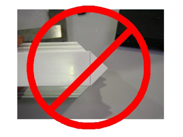
| + | {{Warning|...Do NOT check the arrow head position with a square across the small face. This has been known on several occasions to show an error on the profile, and fools the unwary into an adjustment of the central position. This happens because the narrow part of the profile has not been extruded square to the bottom face.}}{{Idea|...The Z blocks can be used to “bias” the profile under these circumstances, but this is no way a fix for the problem; the profile should be rejected.}}<br /></translate> | ||
| + | |Step_Picture_00=TM016_Arrow_Head_Adjustment_on_Saw_image7.jpg | ||
| + | |Step_Picture_01=TM016_Arrow_Head_Adjustment_on_Saw_image8.jpg | ||
| + | }} | ||
| + | {{Tuto Step | ||
| + | |Step_Title=<translate>Adjusting Arrow Head Position</translate> | ||
| + | |Step_Content=<translate># Go to I/O Screen | ||
| + | # Open the front door | ||
| + | # Working on the '''upper''' cylinder of centralise bar D4367, slacken lock nut to rod end P0049. Using a spanner in flats, turn the cylinder rod clockwise to move the central position towards the backfence or anti-clockwise to move the central position away from the backfence. 1 turn will change the distance by about 0.6 mm. | ||
| + | # Run the check again. | ||
| + | # When satisfactory, tighten lock nut to rod end</translate> | ||
| + | |Step_Picture_00=TM016_Arrow_Head_Adjustment_on_Saw_image10.jpg | ||
| + | |Step_Picture_01=TM016_Arrow_Head_Adjustment_on_Saw_image11.jpg | ||
| + | |Step_Picture_01_annotation={"version":"2.4.6","objects":[{"type":"image","version":"2.4.6","originX":"left","originY":"top","left":0,"top":0,"width":299,"height":226,"fill":"rgb(0,0,0)","stroke":null,"strokeWidth":0,"strokeDashArray":null,"strokeLineCap":"butt","strokeDashOffset":0,"strokeLineJoin":"miter","strokeMiterLimit":4,"scaleX":2.01,"scaleY":2.01,"angle":0,"flipX":false,"flipY":false,"opacity":1,"shadow":null,"visible":true,"clipTo":null,"backgroundColor":"","fillRule":"nonzero","paintFirst":"fill","globalCompositeOperation":"source-over","transformMatrix":null,"skewX":0,"skewY":0,"crossOrigin":"","cropX":0,"cropY":0,"src":"https://stuga.dokit.app/images/9/9f/TM016_Arrow_Head_Adjustment_on_Saw_image11.jpg","filters":[]},{"type":"wfarrow2line","version":"2.4.6","originX":"center","originY":"center","left":312,"top":312,"width":126,"height":104,"fill":"rgba(255,0,0,0)","stroke":"#FF0000","strokeWidth":4,"strokeDashArray":null,"strokeLineCap":"round","strokeDashOffset":0,"strokeLineJoin":"miter","strokeMiterLimit":4,"scaleX":1,"scaleY":1,"angle":0,"flipX":false,"flipY":false,"opacity":1,"shadow":null,"visible":true,"clipTo":null,"backgroundColor":"","fillRule":"nonzero","paintFirst":"fill","globalCompositeOperation":"source-over","transformMatrix":null,"skewX":0,"skewY":0,"x1":-63,"x2":63,"y1":52,"y2":-52,"x2a":52.66805979203509,"y2a":-33.0989150697893,"x2b":42.4830192078801,"y2b":-45.438483469823225},{"type":"wfarrow2circle","version":"2.4.6","originX":"center","originY":"center","left":249,"top":364,"width":16,"height":16,"fill":"#aaa","stroke":"#666","strokeWidth":0,"strokeDashArray":null,"strokeLineCap":"butt","strokeDashOffset":0,"strokeLineJoin":"miter","strokeMiterLimit":4,"scaleX":1,"scaleY":1,"angle":0,"flipX":false,"flipY":false,"opacity":0.5,"shadow":null,"visible":true,"clipTo":null,"backgroundColor":"","fillRule":"nonzero","paintFirst":"fill","globalCompositeOperation":"source-over","transformMatrix":null,"skewX":0,"skewY":0,"radius":8,"startAngle":0,"endAngle":6.283185307179586},{"type":"wfarrow2circle","version":"2.4.6","originX":"center","originY":"center","left":375,"top":260,"width":16,"height":16,"fill":"#aaa","stroke":"#666","strokeWidth":0,"strokeDashArray":null,"strokeLineCap":"butt","strokeDashOffset":0,"strokeLineJoin":"miter","strokeMiterLimit":4,"scaleX":1,"scaleY":1,"angle":0,"flipX":false,"flipY":false,"opacity":0.5,"shadow":null,"visible":true,"clipTo":null,"backgroundColor":"","fillRule":"nonzero","paintFirst":"fill","globalCompositeOperation":"source-over","transformMatrix":null,"skewX":0,"skewY":0,"radius":8,"startAngle":0,"endAngle":6.283185307179586}],"height":454,"width":600} | ||
| + | |Step_Picture_02=TM016_Arrow_Head_Adjustment_on_Saw_image12.jpg | ||
| + | |Step_Picture_02_annotation={"version":"2.4.6","objects":[{"type":"image","version":"2.4.6","originX":"left","originY":"top","left":0,"top":0,"width":299,"height":226,"fill":"rgb(0,0,0)","stroke":null,"strokeWidth":0,"strokeDashArray":null,"strokeLineCap":"butt","strokeDashOffset":0,"strokeLineJoin":"miter","strokeMiterLimit":4,"scaleX":2.01,"scaleY":2.01,"angle":0,"flipX":false,"flipY":false,"opacity":1,"shadow":null,"visible":true,"clipTo":null,"backgroundColor":"","fillRule":"nonzero","paintFirst":"fill","globalCompositeOperation":"source-over","transformMatrix":null,"skewX":0,"skewY":0,"crossOrigin":"","cropX":0,"cropY":0,"src":"https://stuga.dokit.app/images/d/d8/TM016_Arrow_Head_Adjustment_on_Saw_image12.jpg","filters":[]},{"type":"wfarrow2line","version":"2.4.6","originX":"center","originY":"center","left":248.5,"top":210.5,"width":157,"height":55,"fill":"rgba(255,0,0,0)","stroke":"#FF0000","strokeWidth":4,"strokeDashArray":null,"strokeLineCap":"round","strokeDashOffset":0,"strokeLineJoin":"miter","strokeMiterLimit":4,"scaleX":1,"scaleY":1,"angle":0,"flipX":false,"flipY":false,"opacity":1,"shadow":null,"visible":true,"clipTo":null,"backgroundColor":"","fillRule":"nonzero","paintFirst":"fill","globalCompositeOperation":"source-over","transformMatrix":null,"skewX":0,"skewY":0,"x1":-78.5,"x2":78.5,"y1":27.5,"y2":-27.5,"x2a":62.26965334214203,"y2a":-13.33751973114319,"x2b":56.979762579580914,"y2b":-28.437753362454018},{"type":"wfarrow2circle","version":"2.4.6","originX":"center","originY":"center","left":170,"top":238,"width":16,"height":16,"fill":"#aaa","stroke":"#666","strokeWidth":0,"strokeDashArray":null,"strokeLineCap":"butt","strokeDashOffset":0,"strokeLineJoin":"miter","strokeMiterLimit":4,"scaleX":1,"scaleY":1,"angle":0,"flipX":false,"flipY":false,"opacity":0.5,"shadow":null,"visible":true,"clipTo":null,"backgroundColor":"","fillRule":"nonzero","paintFirst":"fill","globalCompositeOperation":"source-over","transformMatrix":null,"skewX":0,"skewY":0,"radius":8,"startAngle":0,"endAngle":6.283185307179586},{"type":"wfarrow2circle","version":"2.4.6","originX":"center","originY":"center","left":327,"top":183,"width":16,"height":16,"fill":"#aaa","stroke":"#666","strokeWidth":0,"strokeDashArray":null,"strokeLineCap":"butt","strokeDashOffset":0,"strokeLineJoin":"miter","strokeMiterLimit":4,"scaleX":1,"scaleY":1,"angle":0,"flipX":false,"flipY":false,"opacity":0.5,"shadow":null,"visible":true,"clipTo":null,"backgroundColor":"","fillRule":"nonzero","paintFirst":"fill","globalCompositeOperation":"source-over","transformMatrix":null,"skewX":0,"skewY":0,"radius":8,"startAngle":0,"endAngle":6.283185307179586}],"height":454,"width":600} | ||
| + | }} | ||
| + | {{Tuto Step | ||
| + | |Step_Title=<translate>Absolute Check for Accuracy</translate> | ||
| + | |Step_Content=<translate>Using four cut pieces, arrange them in a cross formation. All edges should line up – Use a square to prove the pieces are properly in-line</translate> | ||
| + | |Step_Picture_00=TM016_Arrow_Head_Adjustment_on_Saw_image13.jpg | ||
}} | }} | ||
{{Notes}} | {{Notes}} | ||
{{PageLang | {{PageLang | ||
| + | |Language=en | ||
|SourceLanguage=none | |SourceLanguage=none | ||
|IsTranslation=0 | |IsTranslation=0 | ||
| − | |||
}} | }} | ||
{{Tuto Status | {{Tuto Status | ||
|Complete=Draft | |Complete=Draft | ||
}} | }} | ||
Version actuelle datée du 12 mars 2020 à 15:52
This module guides the engineer on how to correctly adjust the centralising mechanism on Stuga saws. The engineer will need a reasonable mechanical knowledge, and a working knowledge of the operation of the machine.
Sommaire
[masquer]- 1 Introduction
- 2 Pièces et outils
- 3 Étape 1 - Check Centraliser Closes fully
- 4 Étape 2 - Check if Profile is Symmetrical
- 5 Étape 3 - Check 45 / 135 Cut Angles
- 6 Étape 4 - Check Side Fences are Parallel
- 7 Étape 5 - Adjusting Angle Position
- 8 Étape 6 - Adjusting Side Fence Parallel
- 9 Étape 7 - Check Current Arrow Head
- 10 Étape 8 - Adjusting Arrow Head Position
- 11 Étape 9 - Absolute Check for Accuracy
- 12 Commentaires
Introduction
When in arrow head or centralising mode, the pivot point of the saw blade is moved from the bladetofence position to the central position of the current section. The mechanism that achieves this allows for any width of profile from 45 mm to 130 mm. If the arrow head position is not central to the profile, the centraliser position may need to be adjusted
- Pièces et outils
Pièces et outils
Étape 1 - Check Centraliser Closes fully
To check the centraliser closes fully, activate the ‘Clamp Positioner’ and ‘Centralise’ clamp from the IO screen with no profile in the saw cutting area. The side clamps should close down to around 40mm. A regular fault is a small offcut of profile trapped somewhere preventing the centralise clamp closing to the profile.
Étape 2 - Check if Profile is Symmetrical
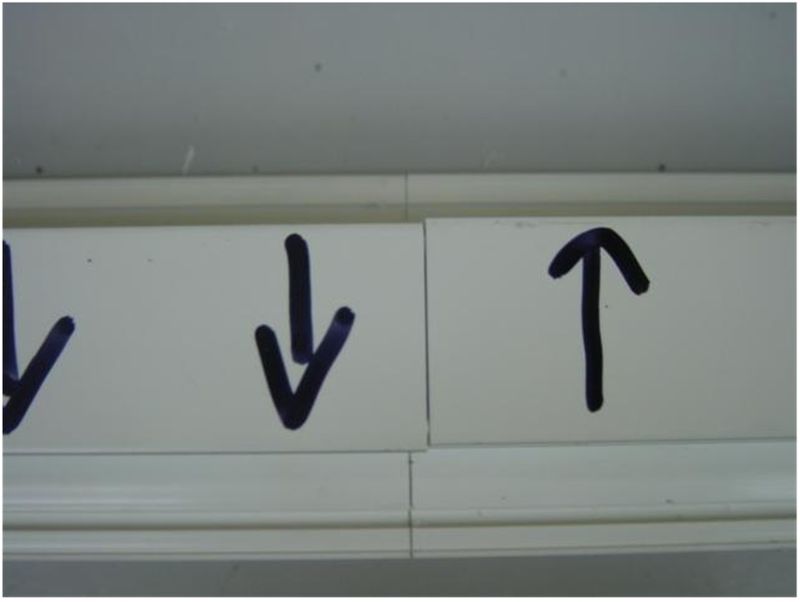
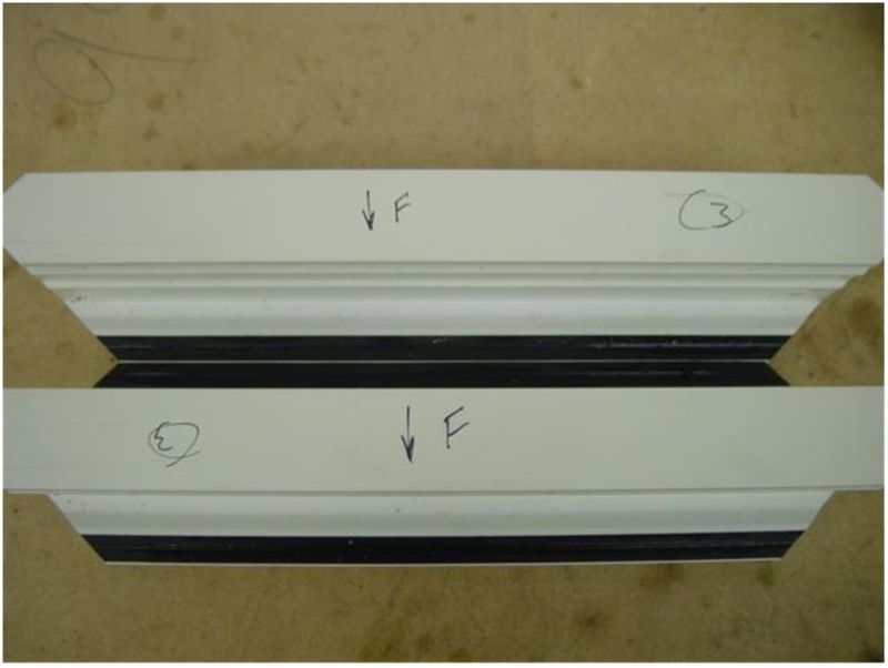
An easy check will demonstrate if there is a profile symmetry issue:
- Cut two lengths of profile [ ] and mark the front face
- Turn one piece around and butt it up to the other piece
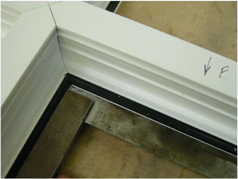
This picture shows a poor quality profile where the narrow face is not centralised to the rest of the profile. The outer edges are lined up, but it is clear that the narrow edges on the top face are not.
Étape 3 - Check 45 / 135 Cut Angles
To check the 45 degree cuts, run off a few 300mm \ / cuts and check the angles
Étape 4 - Check Side Fences are Parallel
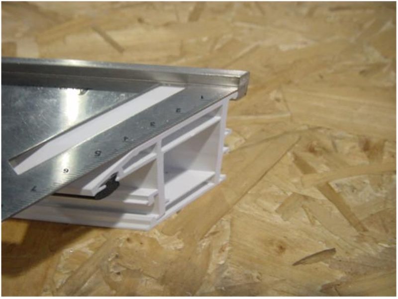
To check side fences are parallel, aluminium reinforcing is best. If none is available use a large outer frame profile in the saw as shown
Move the profile between the 2 side clamps, you should be able to move between the 2 without any side clamp movement when the profile enters or exits the rollers
Étape 5 - Adjusting Angle Position
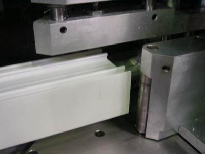
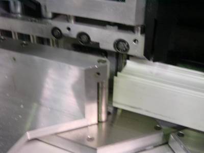
Adjustment can be made to the 45 degree angles with the 45 degree dead stop dampers located below the saw turntable. To adjust, release the locking collar, and turn the damper body. Re-tighten when set.
Étape 6 - Adjusting Side Fence Parallel
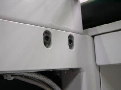
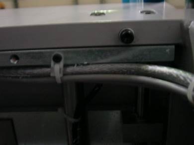
If there is a large error the saw will need altering using the jacking screws on the front. This really is fine adjustment and just tightening up the screws can cause the clamps to move.
Étape 7 - Check Current Arrow Head
- Manually input 4 off 300mm arrow head cuts on a T section ( < > )
- Mark each piece 1, 2, 3, 4 for identification, also mark which side was the front.
- Measure the length of each piece and select two pieces that are the same size, within 0.25mm. This can be done by holding them base to base so that the points line up with each other
- With two similarly size pieces, the arrow head position can be accurately measured by offering the profile edges to each other
- If the front to front and front to rear profile lengths line up within 0.5mm then the arrowhead is within 0.25mm of centre. This is OK
- Run the check again on a wide T section, eg midrail to prove that the system is set for all profile widths
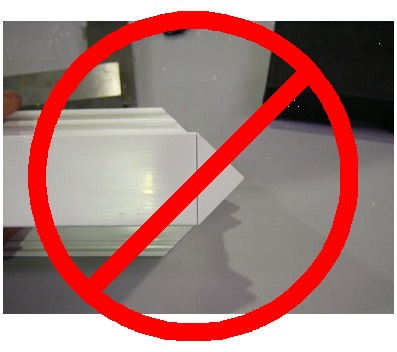
- Check the arrow head position on a Z transom. If the arrow head is out, but is Ok for all T sections, check that the z blocks are correctly adjusted for the profile. The profile may be tipping over because it is unsupported. Also bear in mind that the profile may be inaccurate
Étape 8 - Adjusting Arrow Head Position
- Go to I/O Screen
- Open the front door
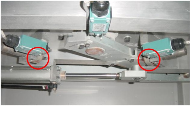
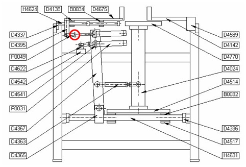
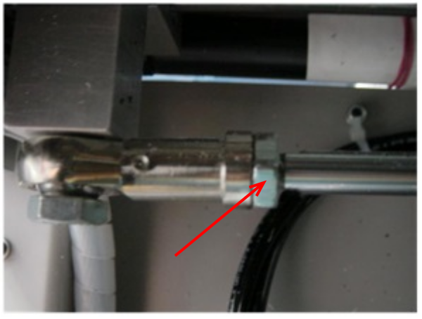
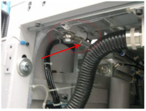
- Working on the upper cylinder of centralise bar D4367, slacken lock nut to rod end P0049. Using a spanner in flats, turn the cylinder rod clockwise to move the central position towards the backfence or anti-clockwise to move the central position away from the backfence. 1 turn will change the distance by about 0.6 mm.
- Run the check again.
- When satisfactory, tighten lock nut to rod end
Étape 9 - Absolute Check for Accuracy
Using four cut pieces, arrange them in a cross formation. All edges should line up – Use a square to prove the pieces are properly in-line
Draft
 Français
 English
 Deutsch
 Español
 Italiano
 Português