| [version en cours de rédaction] | [version en cours de rédaction] |
| (5 révisions intermédiaires par 2 utilisateurs non affichées) | |||
| Ligne 10 : | Ligne 10 : | ||
}} | }} | ||
{{Introduction | {{Introduction | ||
| − | |Introduction=<translate>This upgrade replaces the crank arm assemblies on Z065, Z066 and Z067 with a direct drive system to improve reliability</translate> | + | |Introduction=<translate>This upgrade replaces the crank arm assemblies on Z065, Z066 and Z067 with a direct drive system to improve reliability |
| + | |||
| + | This procedure involves mechanical fitting, electrical wiring and help from a TwinCAT3 competent engineer at HQ for software changes | ||
| + | |||
| + | {{Warning|...The drives must be programmed before parts sent out}}{{Warning|...Motors must be rewired for Delta and NOT Star}} | ||
| + | <br /></translate> | ||
}} | }} | ||
{{Materials}} | {{Materials}} | ||
| Ligne 24 : | Ligne 29 : | ||
Decel time | Decel time | ||
| − | <br /></translate> | + | [[Programming Eaton DE Drive|https://stuga.dokit.app/wiki/Programming_Eaton_DE_Drive]]<br /></translate> |
}} | }} | ||
{{Tuto Step | {{Tuto Step | ||
| Ligne 142 : | Ligne 147 : | ||
|Step_Title=<translate>Add 2 off single pole breaker Module C</translate> | |Step_Title=<translate>Add 2 off single pole breaker Module C</translate> | ||
|Step_Content=<translate>Tidy wires away for the spare 2 phases</translate> | |Step_Content=<translate>Tidy wires away for the spare 2 phases</translate> | ||
| + | |Step_Picture_00=Fitting_Zx5_Crank_Upgrade_DSC_0317.JPG | ||
}} | }} | ||
{{Tuto Step | {{Tuto Step | ||
|Step_Title=<translate>Add 2 off Eaton Drive to Module C</translate> | |Step_Title=<translate>Add 2 off Eaton Drive to Module C</translate> | ||
|Step_Content=<translate>May need to move trunking or mount directly to side of enclosure.</translate> | |Step_Content=<translate>May need to move trunking or mount directly to side of enclosure.</translate> | ||
| + | |Step_Picture_00=Fitting_Zx5_Crank_Upgrade_DSC_0321.JPG | ||
}} | }} | ||
{{Tuto Step | {{Tuto Step | ||
|Step_Title=<translate>Add single pole breaker Module E</translate> | |Step_Title=<translate>Add single pole breaker Module E</translate> | ||
|Step_Content=<translate></translate> | |Step_Content=<translate></translate> | ||
| + | |Step_Picture_00=Fitting_Zx5_Crank_Upgrade_DSC_0322.JPG | ||
}} | }} | ||
{{Tuto Step | {{Tuto Step | ||
| Ligne 158 : | Ligne 166 : | ||
|Step_Title=<translate>Add 1 Off Eaton drive to Module E</translate> | |Step_Title=<translate>Add 1 Off Eaton drive to Module E</translate> | ||
|Step_Content=<translate></translate> | |Step_Content=<translate></translate> | ||
| + | |Step_Picture_00=Fitting_Zx5_Crank_Upgrade_DSC_0326.JPG | ||
}} | }} | ||
{{Tuto Step | {{Tuto Step | ||
| Ligne 198 : | Ligne 207 : | ||
{{Tuto Step | {{Tuto Step | ||
|Step_Title=<translate>Map new Links</translate> | |Step_Title=<translate>Map new Links</translate> | ||
| − | |Step_Content=<translate | + | |Step_Content=<translate>Overwrite existing links if any exist |
| − | + | ||
| − | + | <br />See the wiring for MC2C and MC2E in Step 22 for the link IORefs and locations</translate> | |
| − | |||
| − | |||
| − | |||
| − | |||
| − | |||
| − | |||
| − | |||
| − | |||
| − | |||
| − | |||
| − | |||
| − | |||
| − | |||
| − | |||
| − | |||
| − | |||
| − | |||
| − | |||
| − | |||
| − | |||
| − | |||
| − | |||
| − | |||
| − | |||
| − | |||
| − | |||
| − | |||
| − | |||
| − | |||
| − | |||
| − | |||
| − | |||
| − | |||
| − | |||
| − | |||
|Step_Picture_00=Fitting_Zx5_Crank_Upgrade_Annotation_2019-10-16_141758.jpg | |Step_Picture_00=Fitting_Zx5_Crank_Upgrade_Annotation_2019-10-16_141758.jpg | ||
}} | }} | ||
| Ligne 267 : | Ligne 241 : | ||
{{Tuto Step | {{Tuto Step | ||
|Step_Title=<translate>Test Function</translate> | |Step_Title=<translate>Test Function</translate> | ||
| − | |Step_Content=<translate>Key Pointers | + | |Step_Content=<translate># Ensure all Out and home sensors are working and correctly oriented. Home is towards rear of machine, Fwd or Out is towards front. |
| + | # Ensure the clutches are set to slip if the crank bottoms out | ||
| + | # Test direction of all cranks (Fwd is towards front). Switch phases on motors if direction needs to change. The PLC has hard code to switch the outputs off when the sensors are covered | ||
| + | |||
| + | Key Pointers | ||
| − | * End stops should be set so the rack can never run off the pinion - always a full tooth engaged | + | *End stops should be set so the rack can never run off the pinion - always a full tooth engaged |
| − | * Each crank motion stops when the input is seen, and then decelerates. Therefore, set the crank input position to allow for this deceleration before hitting end stop. Normally about 30mm</translate> | + | *Each crank motion stops when the input is seen, and then decelerates. Therefore, set the crank input position to allow for this deceleration before hitting end stop. Normally about 30mm |
| + | *The crank clutches should be set to slip before damage is done to the crank end stops in the event that the sensors do not work</translate> | ||
}} | }} | ||
{{Notes}} | {{Notes}} | ||
Version actuelle datée du 22 novembre 2019 à 15:28
Fitting the crank upgrade to Z065, Z066, Z067

Difficulté
Difficile
Durée
2 jour(s)
Sommaire
- 1 Introduction
- 2 Étape 1 - Program Eaton Drives before they leave
- 3 Étape 2 - Remove Link arm connecting to rack and pinion
- 4 Étape 3 - Remove pivot shaft and arm
- 5 Étape 4 - Undo clutch and remove Cam
- 6 Étape 5 - Add sprocket to clutch
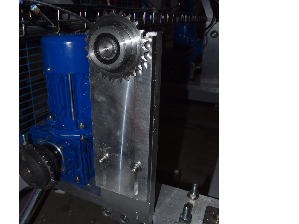
- 7 Étape 6 - Fix idler plate to upright
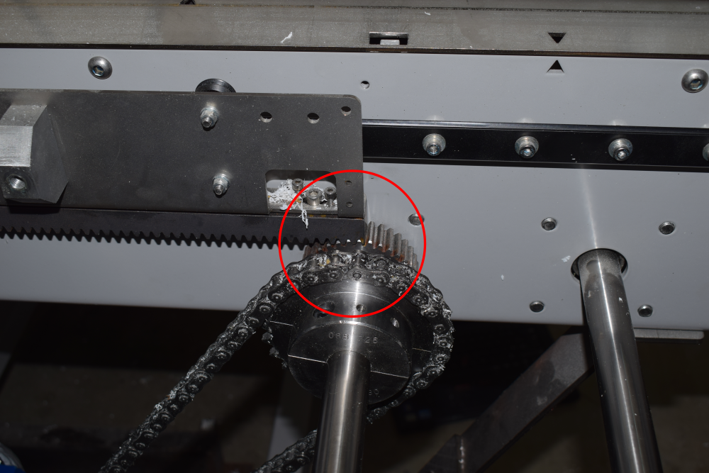
- 8 Étape 7 - Fix split sprocket onto drive shaft
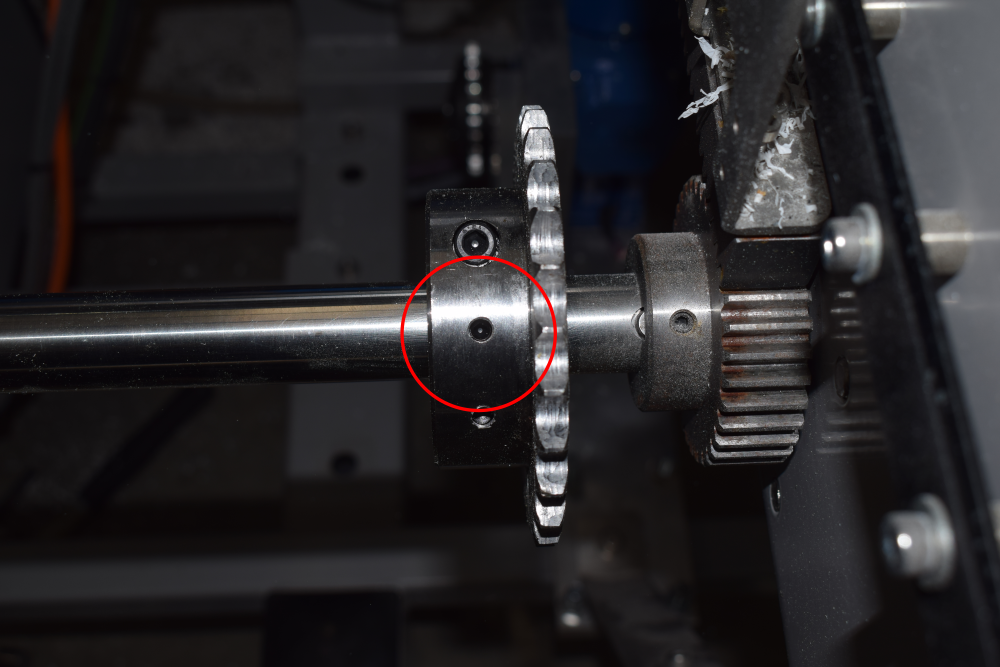
- 9 Étape 8 - Drill and pin split sprocket to shaft
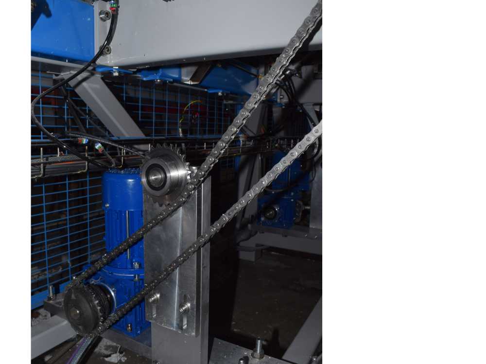
- 10 Étape 9 - Add chain minimum length sprocket to sprocket
- 11 Étape 10 - Fit Module C Crank Home sensor plate to Arm 5
- 12 Étape 11 - Fit Module C Crank Out sensor plate to Arm 5
- 13 Étape 12 - Fit Module D Crank Home sensor plate to Arm 5
- 14 Étape 13 - Fit Module D Crank Out sensor plate to Arm 5
- 15 Étape 14 - Fit Module E Crank Out sensor plate to Arm 5
- 16 Étape 15 - Fit Module E Crank Home sensor plate to Arm 5
- 17 Étape 16 - Remove 2 off breaker and contactor Module C
- 18 Étape 17 - Add 2 off single pole breaker Module C
- 19 Étape 18 - Add 2 off Eaton Drive to Module C
- 20 Étape 19 - Add single pole breaker Module E
- 21 Étape 20 - Remove breaker and contactor Module E
- 22 Étape 21 - Add 1 Off Eaton drive to Module E
- 23 Étape 22 - For each Eaton Drive
- 24 Étape 23 - Wire Sensor Cables to EtherCAT boxes
- 25 Étape 24 - Latest Front End software installed
- 26 Étape 25 - Map new Links
- 27 Étape 26 - Activate Configuration
- 28 Étape 27 - Add new IO Refs to IODef.mul
- 29 Étape 28 - Latest Front End software installed
- 30 Étape 29 - Test Function
- 31 Commentaires
Introduction
This upgrade replaces the crank arm assemblies on Z065, Z066 and Z067 with a direct drive system to improve reliability
This procedure involves mechanical fitting, electrical wiring and help from a TwinCAT3 competent engineer at HQ for software changes
Étape 1 - Program Eaton Drives before they leave
Running frequency
Control mode
Accel time
Decel time
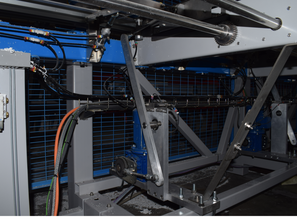
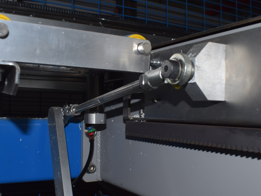
Étape 2 - Remove Link arm connecting to rack and pinion
Étape 3 - Remove pivot shaft and arm


Étape 4 - Undo clutch and remove Cam


Étape 5 - Add sprocket to clutch
B0001166


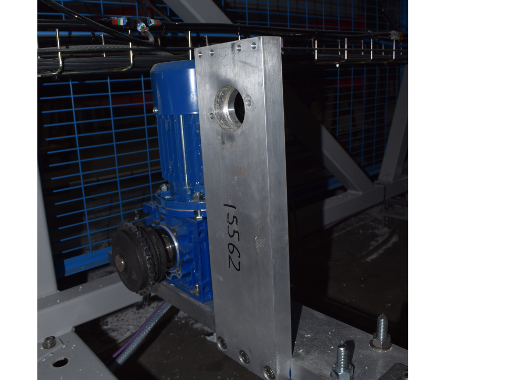
Étape 6 - Fix idler plate to upright
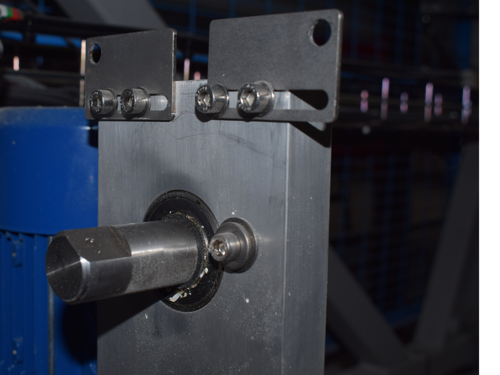
Étape 7 - Fix split sprocket onto drive shaft


Étape 8 - Drill and pin split sprocket to shaft
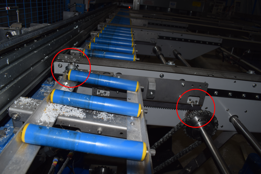
Étape 9 - Add chain minimum length sprocket to sprocket
Use idler to create tension
Étape 10 - Fit Module C Crank Home sensor plate to Arm 5
Sensor cables run to rear Module C cabinet - EtherCAT fieldbus boxes

Étape 11 - Fit Module C Crank Out sensor plate to Arm 5
This one has an extension that may or not be required. See Module D Crank Out Sensor for more info.
Sensor cables run to rear Module C cabinet - EtherCAT fieldbus boxes

Étape 12 - Fit Module D Crank Home sensor plate to Arm 5
Sensor cables run to rear Module C cabinet - EtherCAT fieldbus boxes

Étape 13 - Fit Module D Crank Out sensor plate to Arm 5
This one has an extension
Sensor cables run to rear Module C cabinet - EtherCAT fieldbus boxes


Étape 14 - Fit Module E Crank Out sensor plate to Arm 5
Sensor cables run to rear Module E cabinet - EtherCAT fieldbus boxes


Étape 15 - Fit Module E Crank Home sensor plate to Arm 5
This one has an extension
Sensor cables run to rear Module E cabinet - EtherCAT fieldbus boxes


Étape 16 - Remove 2 off breaker and contactor Module C


Étape 17 - Add 2 off single pole breaker Module C
Tidy wires away for the spare 2 phases

Étape 18 - Add 2 off Eaton Drive to Module C
May need to move trunking or mount directly to side of enclosure.

Étape 19 - Add single pole breaker Module E

Étape 20 - Remove breaker and contactor Module E
Étape 21 - Add 1 Off Eaton drive to Module E

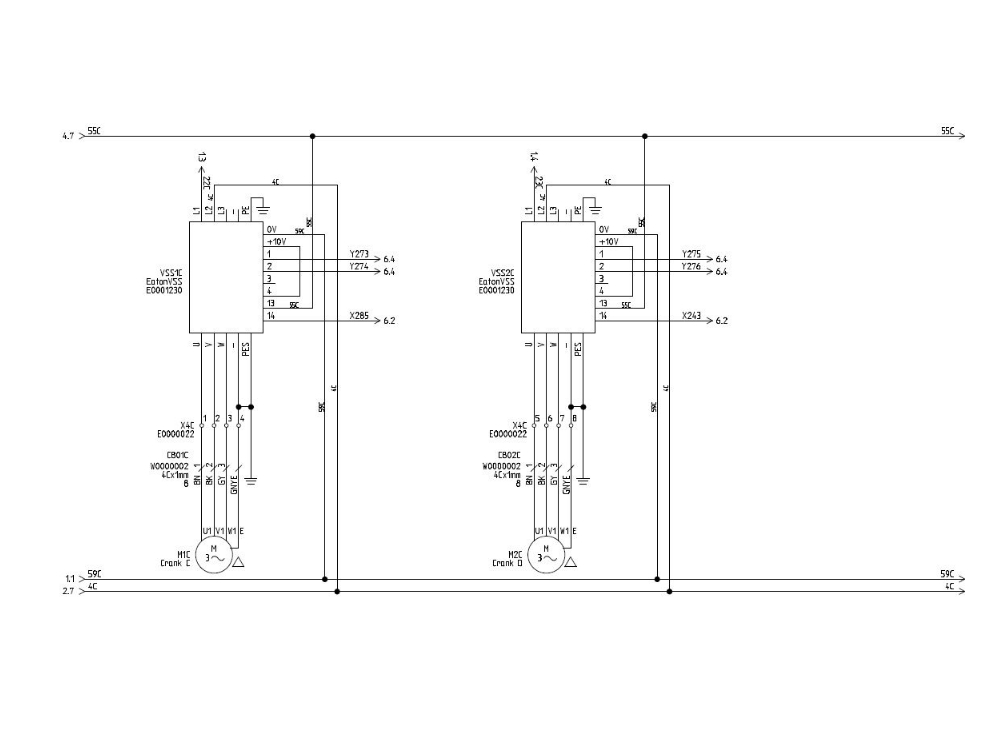
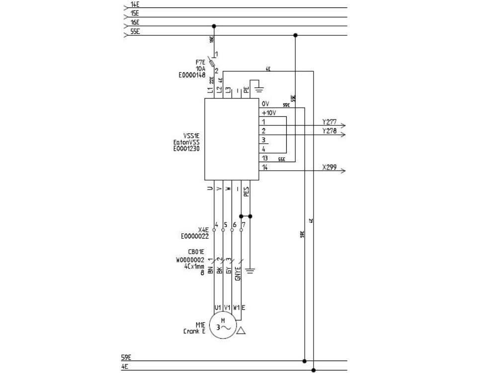
Étape 22 - For each Eaton Drive
- 1 phase
- Neutral
- Earth
- Fwd and Reverse signals
- Wire motor cables directly to bottom of drives
Étape 23 - Wire Sensor Cables to EtherCAT boxes
Module C and D cranks to back of Module C cabinet
Module E crank to back of Module E cabinet


Étape 24 - Latest Front End software installed
- Backup Old multi folder
- Copy in new winMulti version to c:\multi overwriting what is there


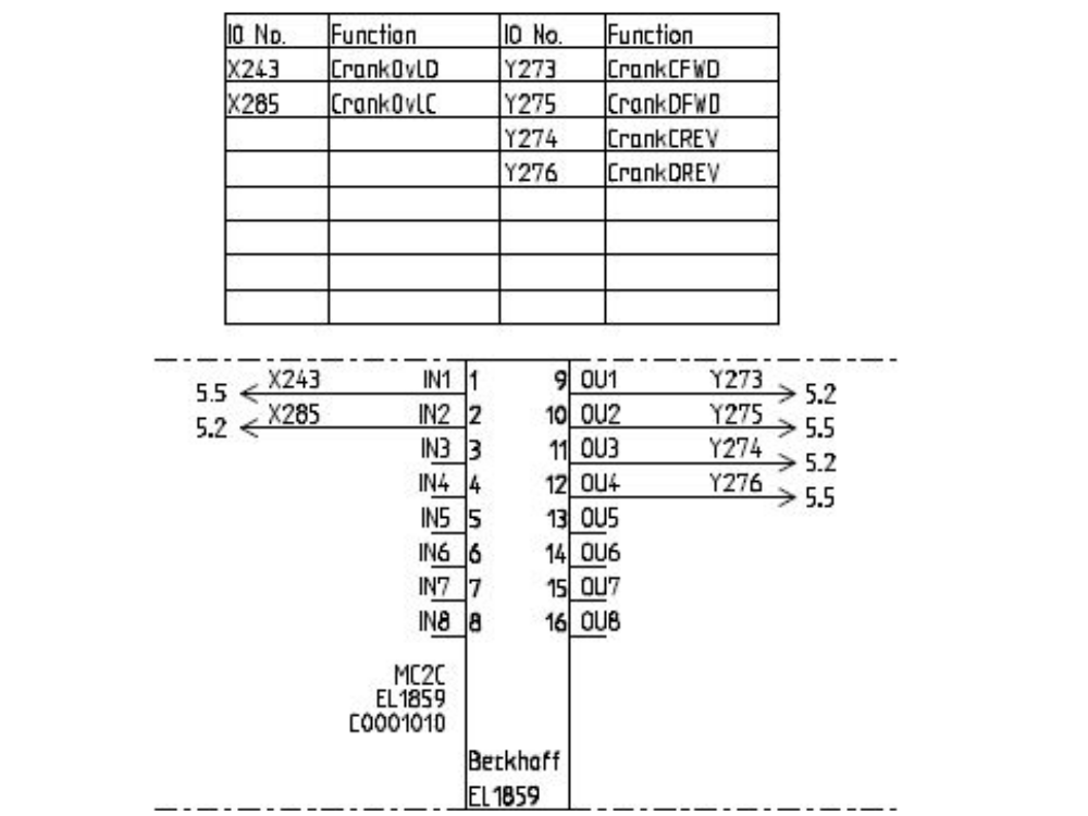
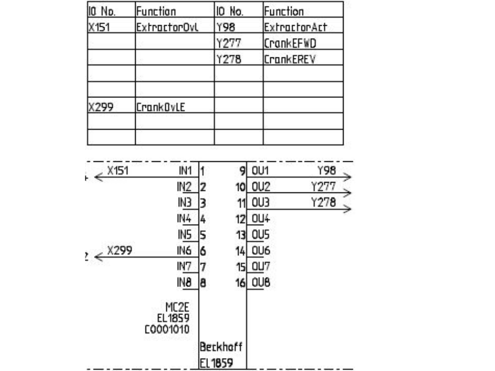
Étape 25 - Map new Links
Overwrite existing links if any exist
See the wiring for MC2C and MC2E in Step 22 for the link IORefs and locations

Étape 26 - Activate Configuration
And restart in run mode when prompted
Étape 27 - Add new IO Refs to IODef.mul
Ask HQ to download a relevant IODef.mul file
OuC_CrankFWD,273,2,0,0,False,False,3,8,-,False,0
OuC_CrankREV,274,2,0,0,False,False,3,9,-,False,0
OuD_CrankFWD,275,2,0,0,False,False,3,10,-,False,0
OuD_CrankREV,276,2,0,0,False,False,3,11,-,False,0
OuE_CrankFWD,277,2,0,0,False,True,64,0,-,False,0
OuE_CrankREV,278,2,0,0,False,True,64,1,-,False,0
And these removed
Étape 28 - Latest Front End software installed
- Backup Old multi folder
- Copy in new winMulti version to c:\multi overwriting what is there
Étape 29 - Test Function
- Ensure all Out and home sensors are working and correctly oriented. Home is towards rear of machine, Fwd or Out is towards front.
- Ensure the clutches are set to slip if the crank bottoms out
- Test direction of all cranks (Fwd is towards front). Switch phases on motors if direction needs to change. The PLC has hard code to switch the outputs off when the sensors are covered
Key Pointers
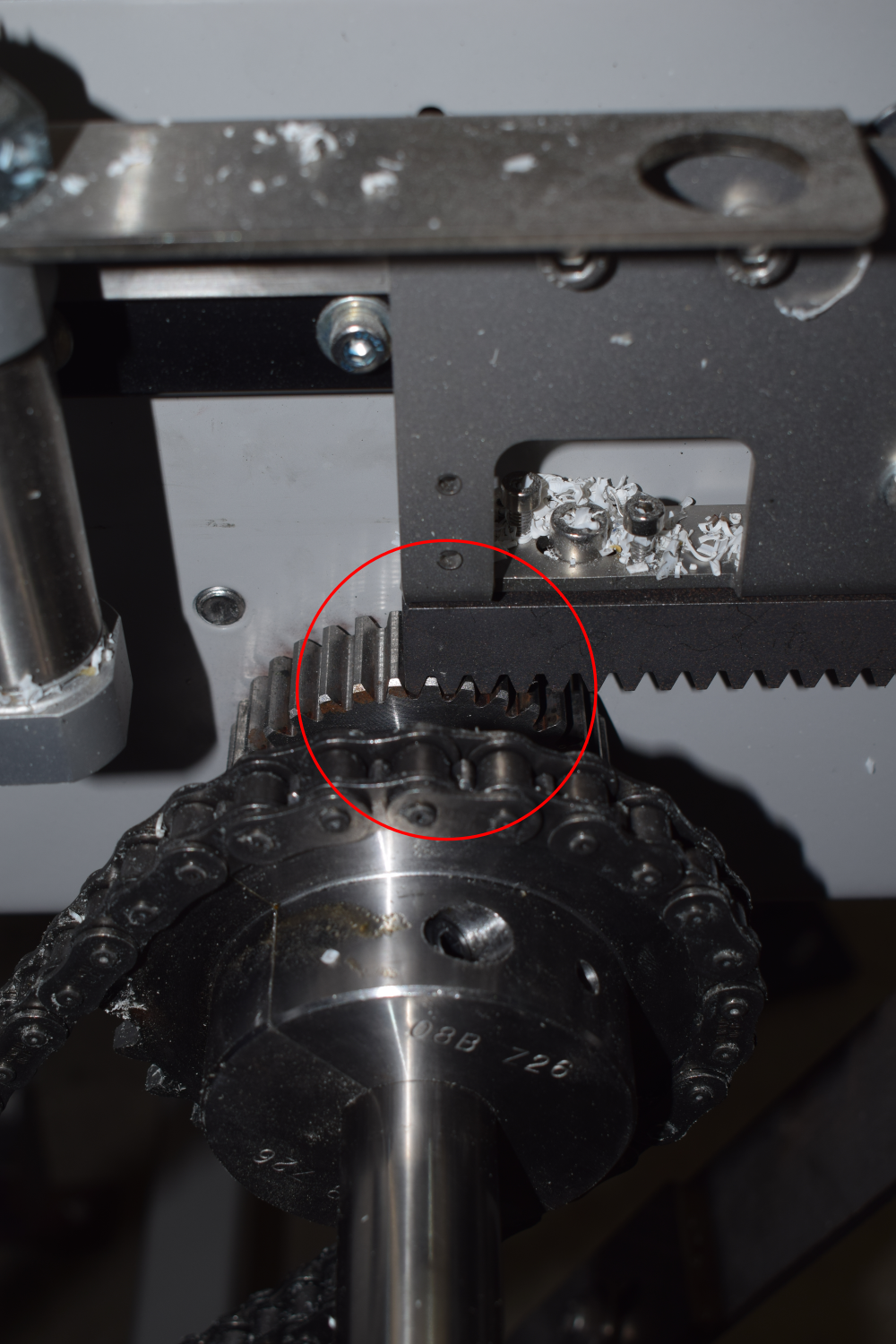
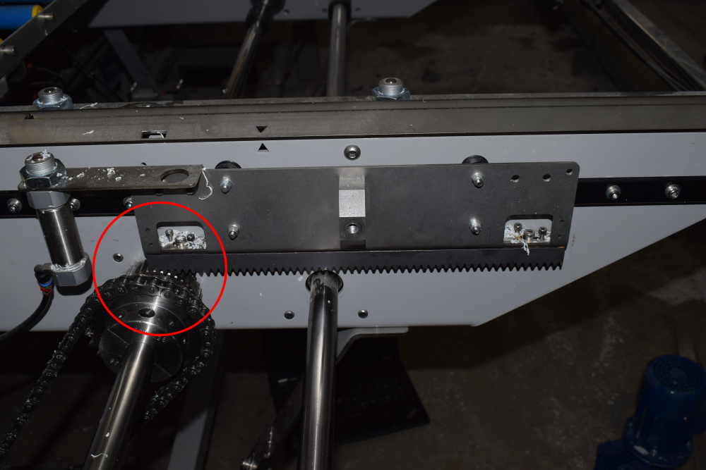
- End stops should be set so the rack can never run off the pinion - always a full tooth engaged
- Each crank motion stops when the input is seen, and then decelerates. Therefore, set the crank input position to allow for this deceleration before hitting end stop. Normally about 30mm
- The crank clutches should be set to slip before damage is done to the crank end stops in the event that the sensors do not work
Draft
 Français
 English
 Deutsch
 Español
 Italiano
 Português