| [version en cours de rédaction] | [version en cours de rédaction] |
| Ligne 46 : | Ligne 46 : | ||
- Safety loop order from safety relay: | - Safety loop order from safety relay: | ||
| − | # Cabinet Estop Button | + | #Cabinet Estop Button |
| − | # Infeed Table Console Estop Button | + | #Infeed Table Console Estop Button |
| − | # Infeed Table Safety Gate Guardswitch | + | #Infeed Table Safety Gate Guardswitch |
| − | # Infeed Table End Estop Button | + | #Infeed Table End Estop Button |
| − | # Machining Centre Front Door Interlock Switch | + | #Machining Centre Front Door Interlock Switch |
| − | # Machining Centre Rear Door Interlock Switch | + | #Machining Centre Rear Door Interlock Switch |
| − | # Sawing Centre Front Door Interlock Switch | + | #Sawing Centre Front Door Interlock Switch |
| − | # Sawing Centre Rear Door Interlock Switch | + | #Sawing Centre Rear Door Interlock Switch |
| − | # Sawing Centre Outfeed Table Estop Button | + | #Sawing Centre Outfeed Table Estop Button |
| − | # Sawing Centre Outfeed Table Safety Gate Guardswitch</translate> | + | #Sawing Centre Outfeed Table Safety Gate Guardswitch |
| + | |||
| + | |||
| + | Notes: | ||
| + | |||
| + | To allow the door unlock signal to work, the safety circuit must be inactive (dumped).</translate> | ||
|Step_Picture_00=Autoflow_Safety_Circuit_Fault_Finding_AF_Mk4.1_Page_1.JPG | |Step_Picture_00=Autoflow_Safety_Circuit_Fault_Finding_AF_Mk4.1_Page_1.JPG | ||
|Step_Picture_01=Autoflow_Safety_Circuit_Fault_Finding_AF_Mk4.1_Page_2.JPG | |Step_Picture_01=Autoflow_Safety_Circuit_Fault_Finding_AF_Mk4.1_Page_2.JPG | ||
Version actuelle datée du 1 avril 2025 à 15:57
This tutorial will guide you through how to find a fault on a safety circuit on all revisions of the Autoflow machine.
Difficulté
Très difficile
Durée
60 minute(s)
Introduction
Étape 1 - Autoflow 2 A2001-A2004
Étape 2 - Autoflow 2 A2005-A2016
Étape 3 - Autoflow 2 A2017-A2022
Étape 4 - Autoflow 2 A2023-A2025 (and A2031)
Étape 5 - Autoflow Mk4 A2026-A2030
Étape 6 - Autoflow Mk4.1 A2032+
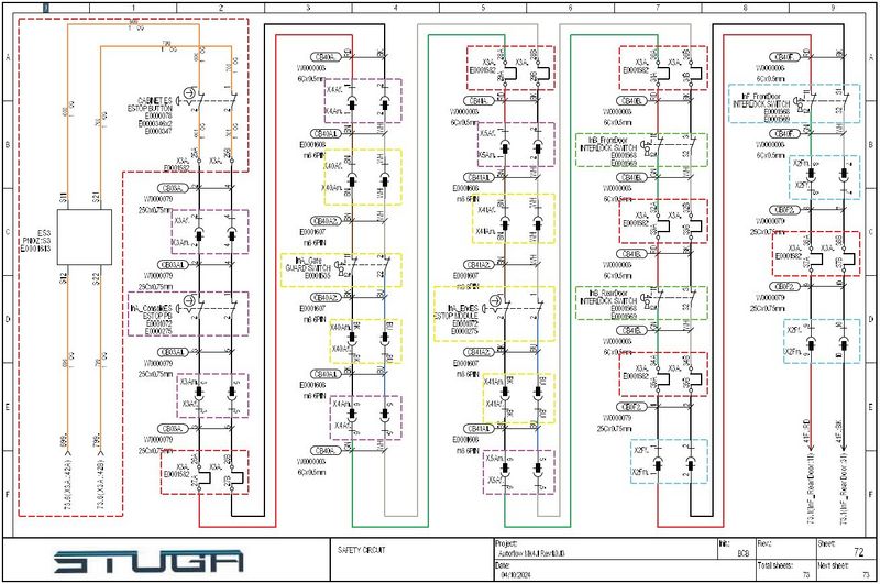
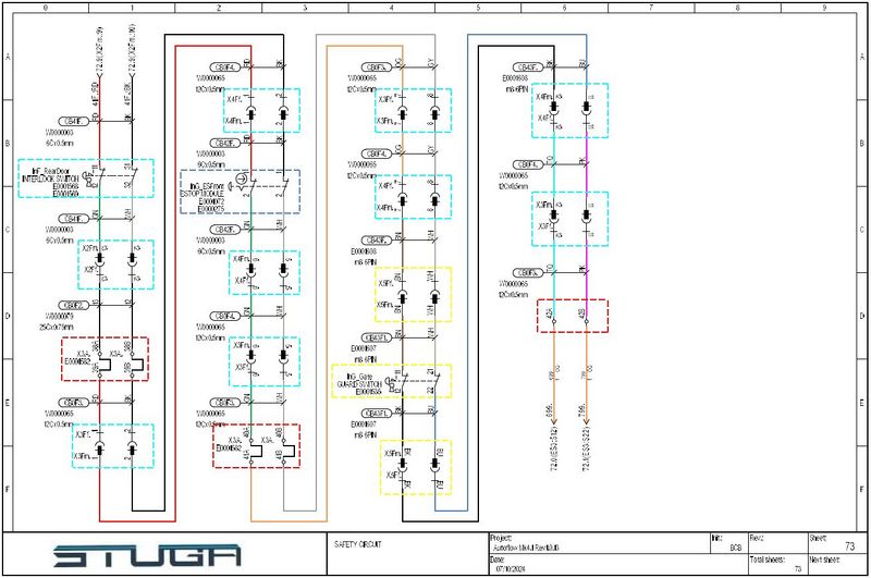
- Dual channel safety circuit controlled by an E0001613 Pilz PNOZs3 safety relay.
- Feedback circuit goes through 2x 24Vdc contactors.
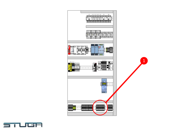
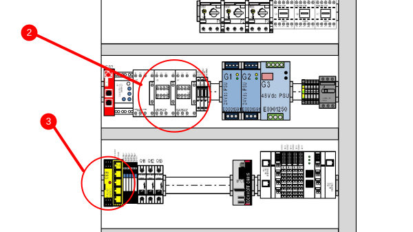
- Picture reference 1 shows where the safety terminals are in the cabinet.
- Safety loop order from safety relay:
- Cabinet Estop Button
- Infeed Table Console Estop Button
- Infeed Table Safety Gate Guardswitch
- Infeed Table End Estop Button
- Machining Centre Front Door Interlock Switch
- Machining Centre Rear Door Interlock Switch
- Sawing Centre Front Door Interlock Switch
- Sawing Centre Rear Door Interlock Switch
- Sawing Centre Outfeed Table Estop Button
- Sawing Centre Outfeed Table Safety Gate Guardswitch
Notes:
To allow the door unlock signal to work, the safety circuit must be inactive (dumped).
Draft


 Français
 English
 Deutsch
 Español
 Italiano
 Português