| [version en cours de rédaction] | [version en cours de rédaction] |
(Page créée avec « {{Tuto Details |Main_Picture=R0015314_Fit_Z_Axis_Drive_components_Screenshot_2023-10-25_093149.png |Main_Picture_annotation={"version":"2.4.6","objects":[{"type":"image","... ») |
|||
| Ligne 363 : | Ligne 363 : | ||
| − | Wind by hand to top travel by rotating leadscrew</translate> | + | Wind by hand to top travel by rotating leadscrew, then again to bottom |
| + | |||
| + | Movement should be smooth and consistent with no tight spots</translate> | ||
| + | |Step_Picture_00=R0000711_Rotary_Base_Assembly_quality-assurance-testing.png | ||
| + | }} | ||
| + | {{Tuto Step | ||
| + | |Step_Title=<translate>Fit servo mount block</translate> | ||
| + | |Step_Content=<translate>Fit servo mount block to driven side | ||
| + | |||
| + | |||
| + | Ensure access hole is facing rear | ||
| + | |||
| + | |||
| + | Dry fit fasteners</translate> | ||
| + | |Step_Picture_00=R0015314_Fit_Z_Axis_Drive_components_Screenshot_2023-10-25_102436.png | ||
| + | }} | ||
| + | {{Tuto Step | ||
| + | |Step_Title=<translate>Attach servo motor</translate> | ||
| + | |Step_Content=<translate>Attach servo motor | ||
| + | |||
| + | |||
| + | Ensure motor is orientated correctly , and servo plug is facing the correct way</translate> | ||
}} | }} | ||
{{Notes}} | {{Notes}} | ||
{{PageLang | {{PageLang | ||
| + | |Language=en | ||
|SourceLanguage=none | |SourceLanguage=none | ||
|IsTranslation=0 | |IsTranslation=0 | ||
| − | |||
}} | }} | ||
{{Tuto Status | {{Tuto Status | ||
|Complete=Draft | |Complete=Draft | ||
}} | }} | ||
Version du 25 octobre 2023 à 11:58
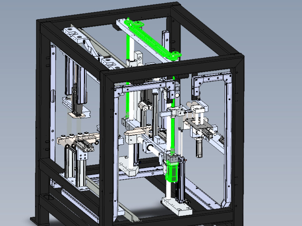
Assembly and setting details for final Z axis component installation

Difficulté
Très difficile
Durée
3 heure(s)
Sommaire
- 1 Introduction
- 2 Étape 1 - Unless otherwise stated
- 3 Étape 2 - Attach leadscrew sleeves
- 4 Étape 3 - Fit front leadscrew
- 5 Étape 4 - Fit rear leadscrew
- 6 Étape 5 - Fix Z axis sleeve to leadscrew
- 7 Étape 6 - Fit top bearings to leadscrews
- 8 Étape 7 - Fit double cylinder brackets
- 9 Étape 8 - Loose fit sprockets
- 10 Étape 9 - Fit chain slide
- 11 Étape 10 - Attach z axis chain
- 12 Étape 11 - Attach chain tensions
- 13 Étape 12 - Adjust sprocket height
- 14 Étape 13 - Tension chain
- 15 Étape 14 - Remove slave side support
- 16 Étape 15 - Fit level to y axis shaft
- 17 Étape 16 - Adjust slave side
- 18 Étape 17 - Tension sprocket
- 19 Étape 18 - Drill leadscrews
- 20 Étape 19 - Check Z axis movement
- 21 Étape 20 - Fit front leadscrew
- 22 Étape 21 - Fit rear leadscrew
- 23 Étape 22 - Fix Z axis sleeve to leadscrew
- 24 Étape 23 - Fit top bearings to leadscrews
- 25 Étape 24 - Fit double cylinder brackets
- 26 Étape 25 - Loose fit sprockets
- 27 Étape 26 - Fit chain slide
- 28 Étape 27 - Attach z axis chain
- 29 Étape 28 - Attach chain tensions
- 30 Étape 29 - Adjust sprocket height
- 31 Étape 30 - Tension chain
- 32 Étape 31 - Remove slave side support
- 33 Étape 32 - Fit level to y axis shaft
- 34 Étape 33 - Adjust slave side
- 35 Étape 34 - Tension sprocket
- 36 Étape 35 - Drill leadscrews
- 37 Étape 36 - Check Z axis movement
- 38 Étape 37 - Fit servo mount block
- 39 Étape 38 - Attach servo motor
- 40 Commentaires
Introduction
Tools Required
Standard hex key set
Standard spanner set
Engineers level 300mm
5mm Carbide drill
150m verniers
Parts Required
A0001069 Energy Chain Series B15.050 (48mm radius) Openable x 2
A0001070 Igus Mounting Br Set for A0001069 Non-Pivot x 2
B0000344 Circlip 15mm External x 2
B0000400 Circlip 17mm External x 2
D0001249 Z Axis Chain Offset Plate x 1
D0001271 Z Axis Chain Mounting Plate x 1
D0001927 Intermediate Housing (AM3032) x 1
D0006498 Z Housing Cap x 2
D0007453 Double Cylinder Bracket OH (D8106) x 1
D0007610 Chain Slide x 1
D0007795 Nut Housing x 1
D0007796 Nut Housing - Mirror x 1
D0007858 Kit: Z Axis Drive Chain ZX + Micro x 1
D0008106 Double Cylinder Bracket (D7453) x 1
H0007714 Z Spocket 20 teeth x 2
R0000963E Bench Assemble Z axis Components x 1
Étape 1 - Unless otherwise stated
Use Loctite 243 on all fasteners
Use Loctite 572 on all threaded pneumatic connection
Pen mark all fasteners to show finalised

Étape 2 - Attach leadscrew sleeves
Fit pre assembled leadscrew sleeves to front and rear Z axis
Bearing fit and solvent if bearing fit is loose
Captivate with Z housing cap


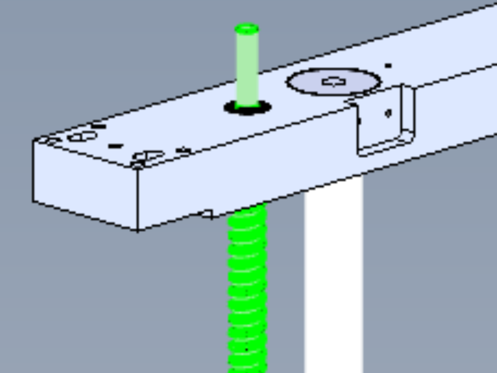
Étape 3 - Fit front leadscrew
Slide onto leadscrew nut Z nut housing
Insert into frame leadscrew
Fit z nut housing to tie beam


Étape 4 - Fit rear leadscrew
Slide onto leadscrew nut Z nut housing
Insert into frame leadscrew
Fit z nut housing to tie beam


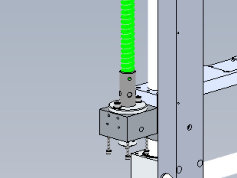
Étape 5 - Fix Z axis sleeve to leadscrew
Align dimples and fix with M8 x 12 kcp grubscrews
Repeat other side
Étape 6 - Fit top bearings to leadscrews
Fit 2 off bearings to top of each leadscrew. Use bearing and solvent if loose .
Captivate with circlip
Étape 7 - Fit double cylinder brackets
Fit double cylinder mounts
Ensure blocks are fitted flush


Étape 8 - Loose fit sprockets
Attach sprockets to leadscrews . Do not finalise fasteners

Étape 9 - Fit chain slide
Fit chain slide to top bar

Étape 10 - Attach z axis chain
Attach Z axis chain around sprockets
Ensure chain join clips are facing upwards

Étape 11 - Attach chain tensions
Attach chain tensioners to top bar
Ensure mounting at highest point up (clearance in fixing holes )

Étape 12 - Adjust sprocket height
Measure height of tensioner sprockets from top bar and set drive sprockets to same measurement
Use verniers
Apply final tension to driven side (side with servo motor mounting point)

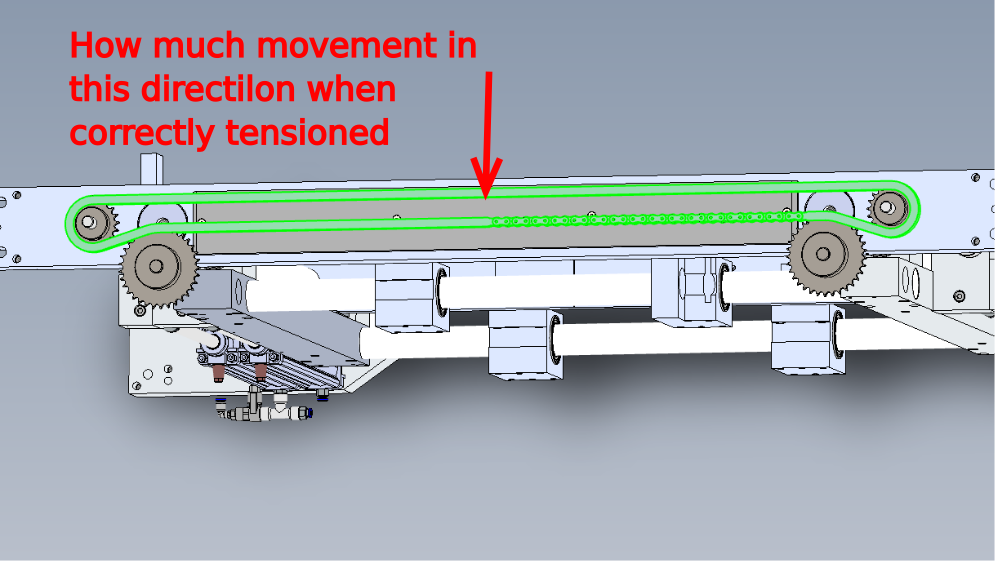
Étape 13 - Tension chain
Tension chain by using adjusting grubscrew on tensioners
Set chain tension to remove slack
Sam, Can you measure the amount of chain flex once set correctly please
Étape 14 - Remove slave side support
Remove slave side bearing support
Étape 15 - Fit level to y axis shaft
Fit engineers level to Y axis shaft

Étape 16 - Adjust slave side
Adjust slave side relationship between sprocket and leadscrew by rotating leadscrew with sprocket fixings loose
Adjust to bring shaft level
Étape 17 - Tension sprocket
Check sprocket height is still correct then apply final tension to fixings in sprocket
Étape 18 - Drill leadscrews
individually remove fixing grubscrews, dimple leadscrew through sprocket with 5mm carbide drill, clean swarf, apply adhesive and refit grubscrew
Repeat for all 4 fixing grubscrews in sprockets

Étape 19 - Check Z axis movement
Remove 2nd axis support and allow Z axis to move to bottom of movement
Wind by hand to top travel by rotating leadscrew
Étape 20 - Fit front leadscrew
Slide onto leadscrew nut Z nut housing
Insert into frame leadscrew
Fit z nut housing to tie beam
Étape 21 - Fit rear leadscrew
Slide onto leadscrew nut Z nut housing
Insert into frame leadscrew
Fit z nut housing to tie beam
Étape 22 - Fix Z axis sleeve to leadscrew
Align dimples and fix with M8 x 12 kcp grubscrews
Repeat other side
Étape 23 - Fit top bearings to leadscrews
Fit 2 off bearings to top of each leadscrew. Use bearing and solvent if loose .
Captivate with circlip
Étape 24 - Fit double cylinder brackets
Fit double cylinder mounts
Ensure blocks are fitted flush
Étape 25 - Loose fit sprockets
Attach sprockets to leadscrews . Do not finalise fasteners
Étape 26 - Fit chain slide
Fit chain slide to top bar
Étape 27 - Attach z axis chain
Attach Z axis chain around sprockets
Ensure chain join clips are facing upwards
Étape 28 - Attach chain tensions
Attach chain tensioners to top bar
Ensure mounting at highest point up (clearance in fixing holes )
Étape 29 - Adjust sprocket height
Measure height of tensioner sprockets from top bar and set drive sprockets to same measurement
Use verniers
Apply final tension to driven side (side with servo motor mounting point)
Étape 30 - Tension chain
Tension chain by using adjusting grubscrew on tensioners
Set chain tension to remove slack
Sam, Can you measure the amount of chain flex once set correctly please
Étape 31 - Remove slave side support
Remove slave side bearing support
Étape 32 - Fit level to y axis shaft
Fit engineers level to Y axis shaft
Étape 33 - Adjust slave side
Adjust slave side relationship between sprocket and leadscrew by rotating leadscrew with sprocket fixings loose
Adjust to bring shaft level
Étape 34 - Tension sprocket
Check sprocket height is still correct then apply final tension to fixings in sprocket
Étape 35 - Drill leadscrews
individually remove fixing grubscrews, dimple leadscrew through sprocket with 5mm carbide drill, clean swarf, apply adhesive and refit grubscrew
Repeat for all 4 fixing grubscrews in sprockets
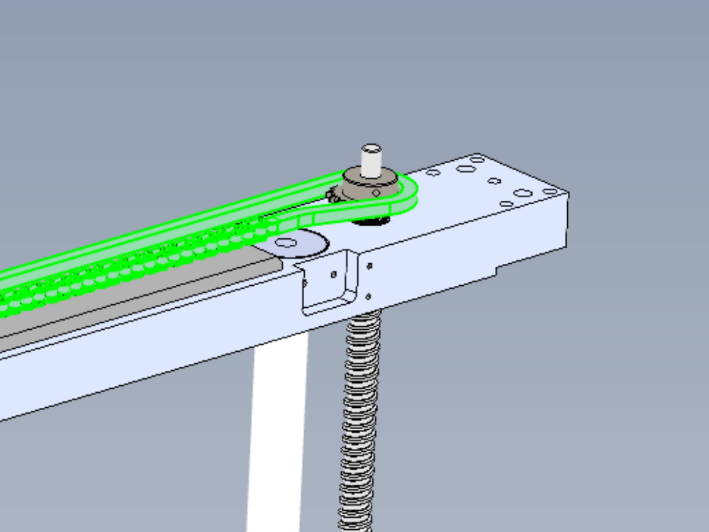
Étape 36 - Check Z axis movement
Remove 2nd axis support and allow Z axis to move to bottom of movement
Wind by hand to top travel by rotating leadscrew, then again to bottom
Movement should be smooth and consistent with no tight spots

Étape 37 - Fit servo mount block
Fit servo mount block to driven side
Ensure access hole is facing rear
Dry fit fasteners

Étape 38 - Attach servo motor
Attach servo motor
Ensure motor is orientated correctly , and servo plug is facing the correct way
Draft
 Français
 English
 Deutsch
 Español
 Italiano
 Português