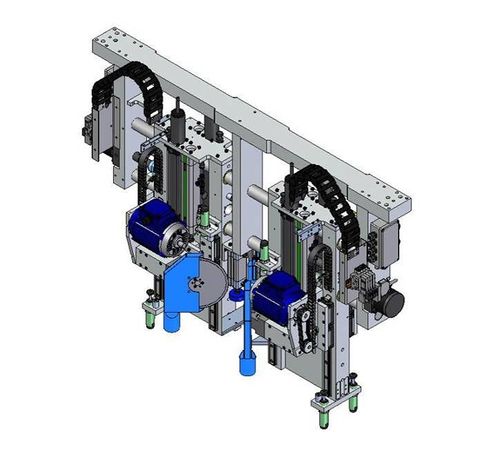
Description and architecture of the ZX4 machining module.
Machining Module
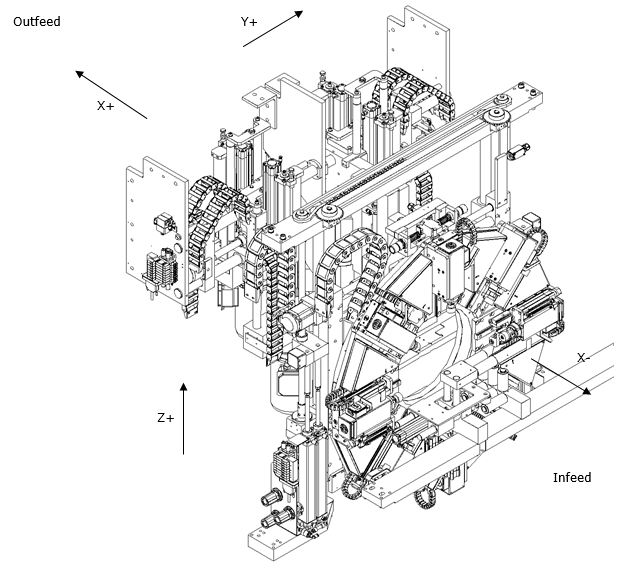
The Machining Centre comprises of the prepping and notching ring assembly. The Vee notching blades are positioned at the rear of the Machining Centre on the ZX4and on the R axis (Ring) on the ZX. All cutting, prepping and notching is contained in this module.
The ZX4 operates on 7 axes and the ZX3 on 5 axes.
| Axis | Description |
| X | Horizontal linear Infeed and Outfeed axis |
| Y | Horizontal linear axis at right angles to the X axis |
| Z | Vertical linear axis at right angles to the X axis |
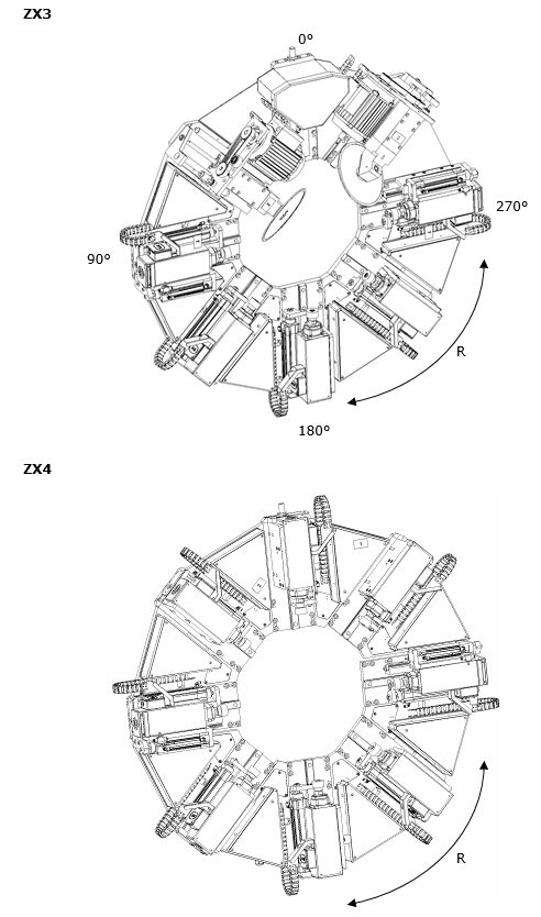
| R | Rotational axis of the Multihead Ring |
| S | Gripper side to side |
| V | Front V notch axis (ZX4) |
| W | Rear V notch axis (ZX4) |
Prepping and Notching Ring
The prepping and notching is performed using the front ring assembly or ‘R’ Axis. This is designed to cut any combination and number of drainage holes, espag preps and routed slots. The ZX3 also uses this axis for Vee Notching .
Vee Notch Assembly (ZX4)
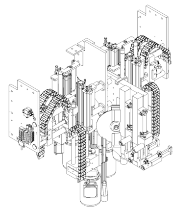
The Vee notch assembly is positioned at the rear of the Machining Centre on a ZX4 and on the R axis on a ZX. This is illustrated below.
Original Version Z001 – Z016
Draft
 Français
 English
 Deutsch
 Español
 Italiano
 Português