Guide for basic Input and Output testing / setup on the ZX5 MH Infeed Module


Difficulté
Moyen
Durée
4 heure(s)
Introduction
The MH infeed on a ZX5 is a module which can be tested individually away from the fully installed machine. Once build stage is complete, to be able to test individually, the Infeed Module needs:
- To be connected to mains power & be powered on
- An air supply to the main blue line
- Network connection (Network Cube)
- HDMI & Keyboard dongle to be plugged into the Beckhoff PLC inside the cabinet.
Input and output activation when testing the sole module is done through the Twincat project rather than through WinMulti
Étape 1 - Open Winmulti software from desktop

Étape 2 - Emergency Stop and Reset Test
Make sure the reset of the Estop circuit works. Be aware when resetting this will reset the air to home all pneumatics.
Test each emergency stop button individually (Button box, infeed rear middle and end) making sure this breaks the circuit when pressed and the air is dumped. The Infeed beam sensor should be tested, when broken should also break the circuit and dump the air.
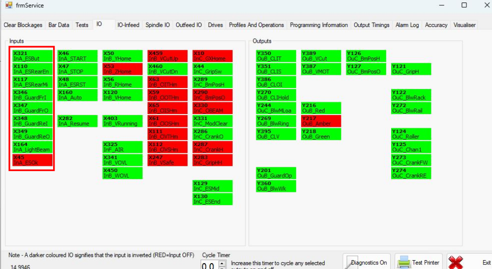
Check on Service menu - IO tab that each input works correctly for each Estop unit.
Étape 3 - Roller Bed Pneumatic test
The home position of the roller beds should be up when the Estop circuit is ok and air is on.
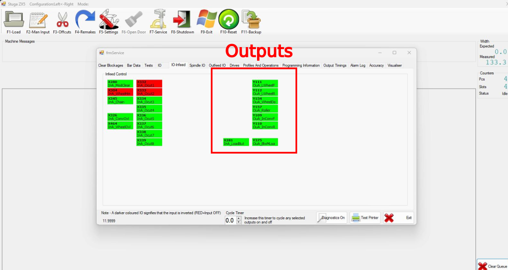
Open the Service menu - IO infeed tab and use the output Y157 OUA_Roller to activate, moving the roller beds to the down position under the infeed plastics.
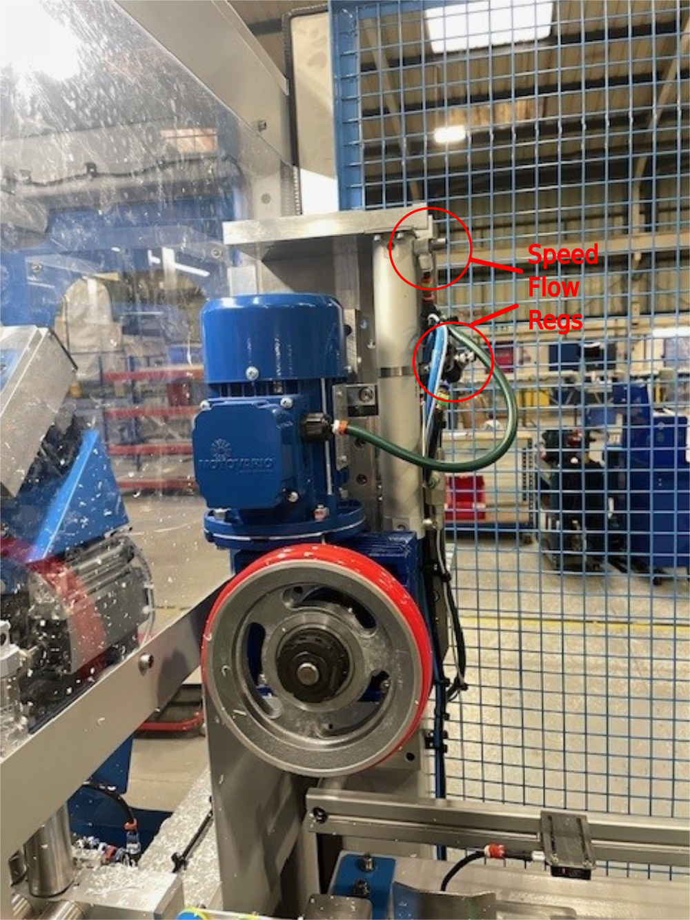
If they are moving the correct orientation, ensure all beds move up and down together, and arrive to position at the same speed or as close to as possible. Speeds should be roughly set when roller bed units are assembled. A rough setting is to wind each flow reg fitting completely in and then wind out 2 full turns.
Some may need tweaking to even out the speeds across all tables.
Étape 4 - Infeed Loader Wheel Pneumatic test
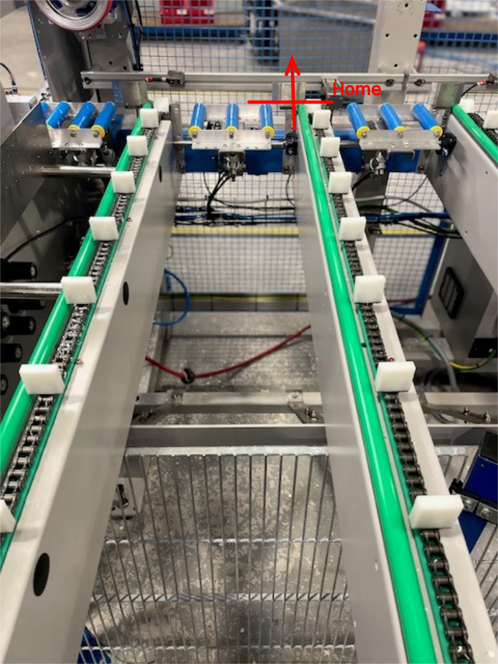
Home position for the loader is up on the rubber stop.
home sensor Input X304 InA_WheelHm should be on (red) when the loader wheel is up in the home position. if it isn't the sensor on the cylinder needs to be adjusted.
Activate the loader wheel down using Output Y154 OuA_WheelDo. When activated set the pressure gauge on the back of the infeed cabinet to around 1Bar.
Adjust the flow reg fittings to set the speed of the wheel down and wheel home. See video for rough speed required.
Étape 5 - Inverter set up
Follow guide xxxxx to set the correct parameters in on the Infeed chain / pegs and loader wheel inverters.
Draft
 Français
 English
 Deutsch
 Español
 Italiano
 Português