| [version en cours de rédaction] | [version en cours de rédaction] |
(Page créée avec « {{Tuto Details |Main_Picture=R0015352_Mount_Buffer_Beams_Screenshot_2023-10-31_073710.png |Main_Picture_annotation={"version":"2.4.6","objects":[{"type":"image","version":... ») |
|||
| Ligne 67 : | Ligne 67 : | ||
Use fix through method with M8 buttons and m8 plate nuts</translate> | Use fix through method with M8 buttons and m8 plate nuts</translate> | ||
|Step_Picture_00=R0015352_Mount_Buffer_Beams_Screenshot_2023-10-31_080208.png | |Step_Picture_00=R0015352_Mount_Buffer_Beams_Screenshot_2023-10-31_080208.png | ||
| + | }} | ||
| + | {{Tuto Step | ||
| + | |Step_Title=<translate>Add tie bases</translate> | ||
| + | |Step_Content=<translate>Add tie bases to 4 off fence supports</translate> | ||
| + | |Step_Picture_00=R0015352_Mount_Buffer_Beams_Screenshot_2023-10-31_081734.png | ||
}} | }} | ||
{{Tuto Step | {{Tuto Step | ||
| Ligne 114 : | Ligne 119 : | ||
{{Notes}} | {{Notes}} | ||
{{PageLang | {{PageLang | ||
| + | |Language=en | ||
|SourceLanguage=none | |SourceLanguage=none | ||
|IsTranslation=0 | |IsTranslation=0 | ||
| − | |||
}} | }} | ||
{{Tuto Status | {{Tuto Status | ||
|Complete=Draft | |Complete=Draft | ||
}} | }} | ||
Version du 31 octobre 2023 à 10:17
Details for mounting front and rear buffer/support bars

Difficulté
Moyen
Durée
4 heure(s)
Sommaire
- 1 Introduction
- 2 Étape 1 - Unless otherwise stated
- 3 Étape 2 - Assemble corner posts
- 4 Étape 3 - Add tie bases
- 5 Étape 4 - Attach fence supports
- 6 Étape 5 - Attach Corner posts
- 7 Étape 6 - Assemble buffer bars
- 8 Étape 7 - Attach buffer bar rear
- 9 Étape 8 - attach front buffer support brackets
- 10 Étape 9 - attach front buffer bar
- 11 Commentaires
Introduction
Tools Required
Standard hex key set
Standard spanner set
1 meter spirit level
Tape measure
Parts Required
D0015326 transfer gate upright x 4
D0015334 ZX fence corner post x 2
D0015607 Fence 11 support beam x 4
D0015335 ZX fence cross post x 4
D0010202 Frame joining plate x 2
D0015232 Fence mounting bracket x 2
M0001016 angle bracket x 2
M0000516 adjustable foot x 2
Étape 1 - Unless otherwise stated
Use Loctite 243 on all fasteners
Use Loctite 572 on all threaded pneumatic connection
Pen mark all fasteners to show finalised

Étape 2 - Assemble corner posts
assemble 2 off corner post assemblies
2 off corner post
4 off upright
Use fix through method with M8 buttons and m8 plate nuts

Étape 3 - Add tie bases
Add tie bases to 4 off fence supports

Étape 4 - Attach fence supports
Attach 4 off fence supports to module C and E frames

Étape 5 - Attach Corner posts
attach pre assembled corner posts to fence supports

Étape 6 - Assemble buffer bars
Assemble 2 off buffer bars
each buffer bar consists of 2 buffer bar sections and 1 joining plate

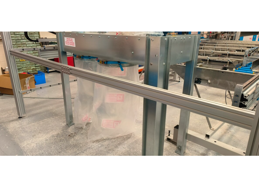
Étape 7 - Attach buffer bar rear
Attach rear buffer bar.
Fix in position with 2 off angle bracket
include all data for correct position setting


Étape 8 - attach front buffer support brackets
Attach 2 off brackets to blue section on module C and E frames

Étape 9 - attach front buffer bar
Attach front buffer bar
Capture details for correct position , height and setting level

Draft
 Français
 English
 Deutsch
 Español
 Italiano
 Português