Details for manual pneumatic output testing on module

Difficulté
Moyen
Durée
1 heure(s)
Sommaire
- 1 Introduction
- 2 Étape 1 - Safety
- 3 Étape 2 - Set Air service unit soft start
- 4 Étape 3 - Check all open ports
- 5 Étape 4 - Connect main PCL
- 6 Étape 5 - Check for leaks
- 7 Étape 6 - Manual overide
- 8 Étape 7 - Check for leaks
- 9 Étape 8 - Check home positions
- 10 Étape 9 - home positions for outputs
- 11 Étape 10 - home positions for outputs
- 12 Étape 11 - If any deviation from the above
- 13 Étape 12 - Manual valve over ride
- 14 Étape 13 - Y80 Clamp infeed top
- 15 Étape 14 - Y82 Clamp outfeed top
- 16 Étape 15 - Y91 Eject
- 17 Étape 16 - Y202 Side clamp
- 18 Étape 17 - Y204 Clamp position
- 19 Étape 18 - Y206 Centralise
- 20 Étape 19 - Y207 saw cut
- 21 Étape 20 - Y210 Z support infeed
- 22 Étape 21 - Y212 Hi low pressure
- 23 Étape 22 - Y213 Saw blowers
- 24 Étape 23 - Y214 Z turret infeed
- 25 Étape 24 - Y215 Z turret outfeed
- 26 Étape 25 - Y224 Z support outfeed
- 27 Étape 26 - output testing complete
- 28 Commentaires
Introduction
Tools Required
PCL airline connection
12mm blanking ports
Valve Manual over ride tool
Standard screwdriver set
Additional colleague when setting regulator pressures for outputs
Parts required
Étape 1 - Safety
Output testing will require valve operation with no e/s circuit
Ensure the following
Work area is clear from all components not required for testing
All colleagues are aware of the procedure being undertaken
No additional colleagues are working on the module
PCL coupling is accessible to release pressure in case of emergency
Testing procedure is fully adhered to

Étape 2 - Set Air service unit soft start
Wind fully out soft start screw situated on top on main air service unit

Étape 3 - Check all open ports
Ensure all open ports and trailing pipes are suitably blanked


Étape 4 - Connect main PCL
Connect main pcl air feed to air service unit
Increase Air service unit pressure to 6.0bar


Étape 5 - Check for leaks
Check for audible leaks on the red pipe lines installed and correct if found
Check air gun regulator functions properly . Fully open the regulator (2 bar limited ) and test air gun assembly


Étape 6 - Manual overide
Enable the manual over ride on the main air service unit
This will purge the system with air.

Étape 7 - Check for leaks
Check for audible leaks on blue Pipe line, and active control pipes to cylinders and regulators


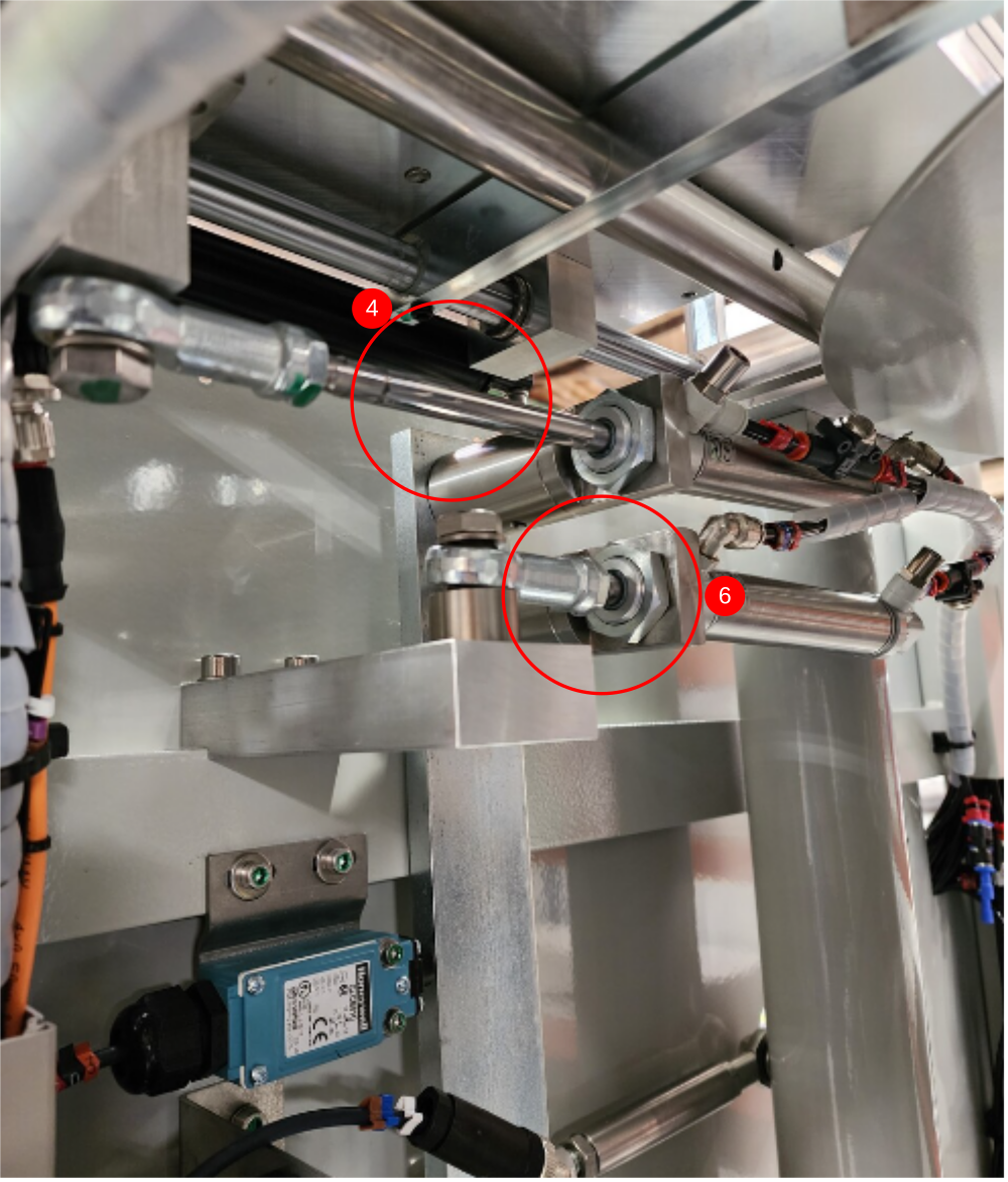
Étape 8 - Check home positions
With the system in the natural state when over ridden, the following cylinder positions should be confirmed
Étape 9 - home positions for outputs
1 Y80 Infeed Top clamp contracted
2 Y82 Outfeed top clamp contracted
3 Y91 eject cylinder contracted
4 Y202 clamp infeed side extended
5 Y204 Clamp pos contracted
6 Y206 Centralise contracted
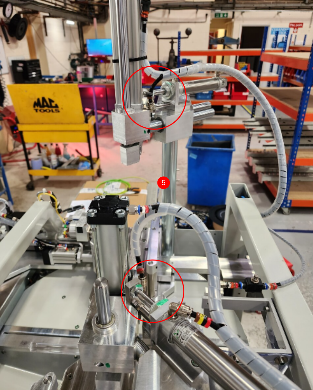
Étape 10 - home positions for outputs
1 Y207 Saw cut contracted
2 Y210 Z support infeed contracted
3 Y213 Saw blowers switched off
4 Y214 Z turret infeed Not moving
5 Y215 Z turret outfeed . Not moving
6 Y224 Z support outfeed contracted
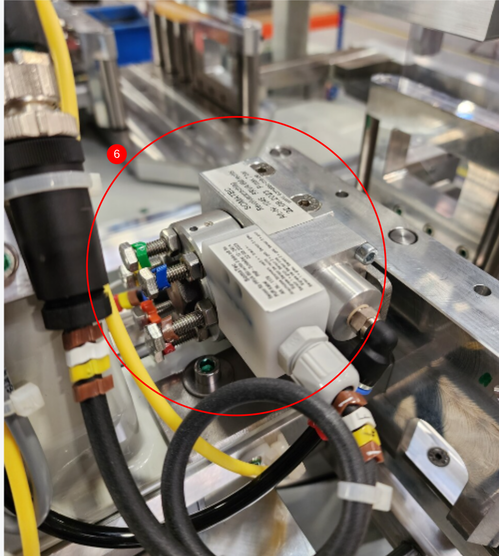
Étape 11 - If any deviation from the above
If any deviation from the above check pipe connections to incorrect output
Étape 12 - Manual valve over ride
Each valve can be manually fired from the over ride button. Pressing this will activate the valve and fire the cylinder /output
when a valve is over ridden, ensure attention is paid to any new air leaks that could become present in the active line when fired


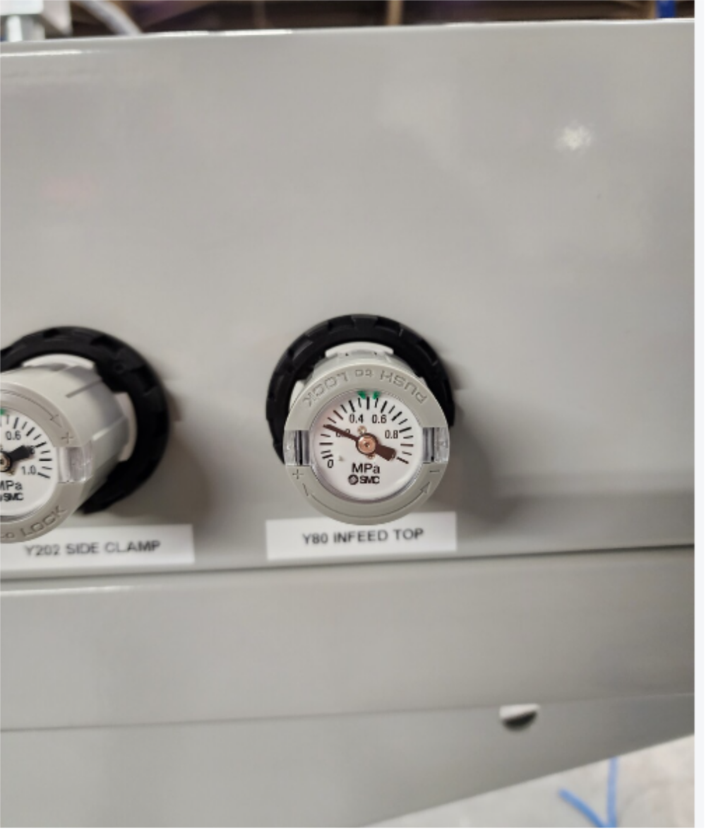
Étape 13 - Y80 Clamp infeed top
Fire and hold valve
Adjust regulator to 0.2 M.P.A
Cylinder should extend
Should retract when valve released


Étape 14 - Y82 Clamp outfeed top
Fire and hold valve
Cylinder should extend
Should retract when valve released


Étape 15 - Y91 Eject
Fire and hold valve
Eject table should move away from saw head
Should retract when valve released


Étape 16 - Y202 Side clamp
Fire and hold valve
Set regulator to 0.2 M.P.A
Side clamp should move towards backfence rollers
Should retract when valve released


Étape 17 - Y204 Clamp position
Fire and hold valve
Clamps should move towards from of machine.
If movement is slow/not present check flow restrictors on back of electrical cabinet identified as 2049
Should retract when valve released


Étape 18 - Y206 Centralise
Fire and hold valve
Set regulator to 2 M.P.A
Saw head should move towards rear of machine
Should retract when valve released


Étape 19 - Y207 saw cut
Fire and hold valve
Saw head should raise up
Should retract when valve released


Étape 20 - Y210 Z support infeed
Fire and hold valve
Infeed side z block should fire towards back fence
Should retract when valve released
Étape 21 - Y212 Hi low pressure
assistance required from colleague
Fire and hold Y80 output , infeed top clamp should move down. Keep Y80 held down
Top clamp block pressure should be weak enough to override by hand and move clamp back towards cylinder
Additionally fire Y212, this should switch clamp to high pressure and stop clamp being able to be over ridden by hand

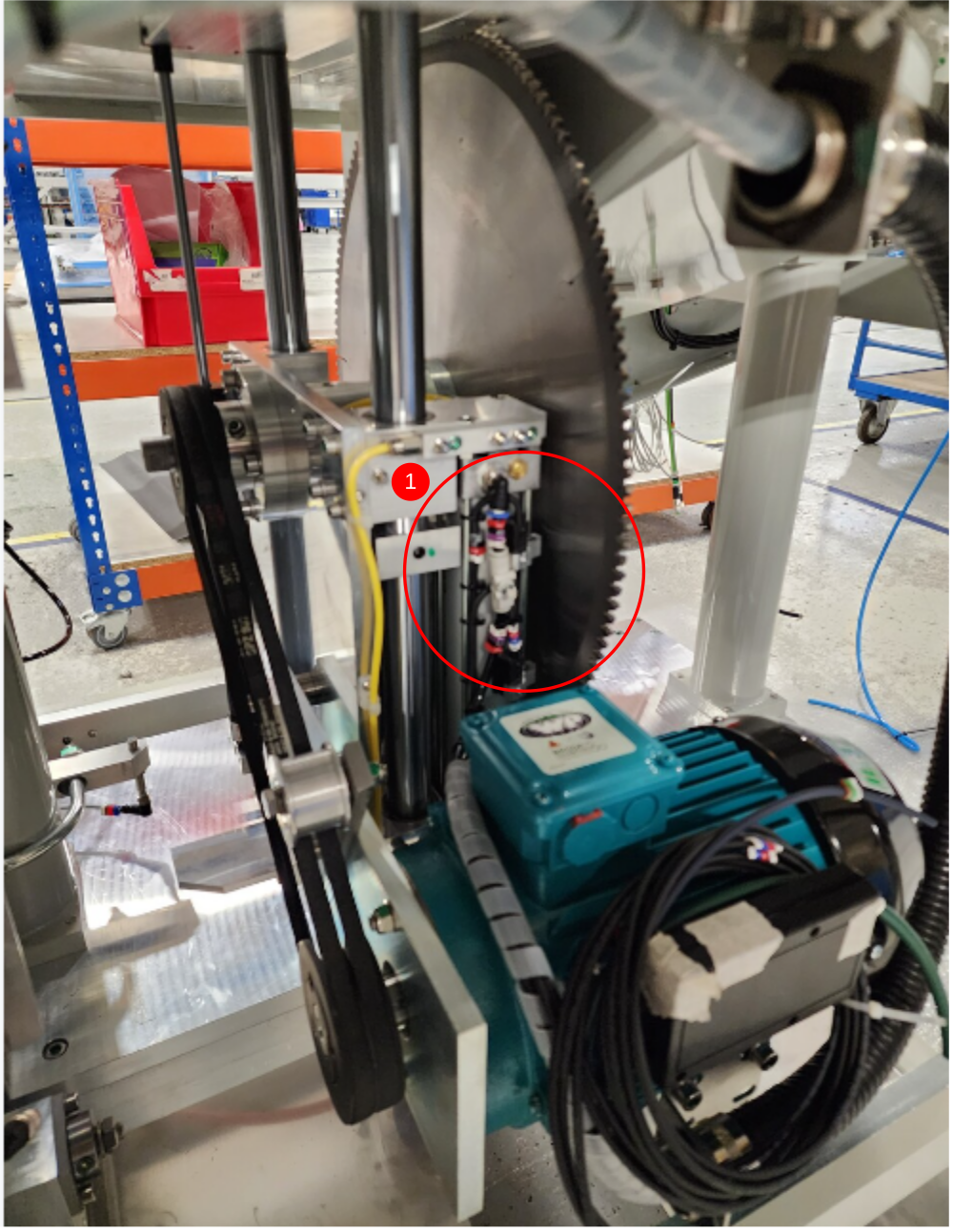
Étape 22 - Y213 Saw blowers
Fire and hold valve
Blowers should switch on
Check operation of inline flow controllers .
When fully closed air flow should stop completely. If air flow can not be completely stopped by flow controller, it is fitted the wrong way around. Change and recheck if this occurs
Étape 23 - Y214 Z turret infeed
Fire and hold valve
Infeed turret should rotate once
Release and fire valve again and turret should again rotate one position
Étape 24 - Y215 Z turret outfeed
Fire and hold valve
Outfeed turret should rotate once
Release and fire valve again and turret should again rotate one position
Étape 25 - Y224 Z support outfeed
Fire and hold valve
Outfeed side z block should fire towards back fence
Should retract when valve released
Étape 26 - output testing complete
Disconnect pcl air supply
Remove temporary blanks fitted

Draft
 Français
 English
 Deutsch
 Español
 Italiano
 Português