| [version en cours de rédaction] | [version en cours de rédaction] |
| Ligne 181 : | Ligne 181 : | ||
| − | Incorporate turret brackets at rear fixing point when mounting saddle brace | + | Incorporate turret brackets at rear fixing point when mounting saddle brace |
| + | |||
| + | Saddle brace has slots for sideways movement. Utilize this to ensure Z turret brackets sit square in position to fences | ||
| Ligne 190 : | Ligne 192 : | ||
|Step_Picture_02=R0015334_Fit_Centralise_Front_Table_Screenshot_2023-12-12_084158.png | |Step_Picture_02=R0015334_Fit_Centralise_Front_Table_Screenshot_2023-12-12_084158.png | ||
|Step_Picture_03=R0015334_Fit_Centralise_Front_Table_Screenshot_2023-12-12_084512.png | |Step_Picture_03=R0015334_Fit_Centralise_Front_Table_Screenshot_2023-12-12_084512.png | ||
| + | |Step_Picture_03_annotation={"version":"2.4.6","objects":[{"type":"image","version":"2.4.6","originX":"left","originY":"top","left":0,"top":0,"width":499,"height":594,"fill":"rgb(0,0,0)","stroke":null,"strokeWidth":0,"strokeDashArray":null,"strokeLineCap":"butt","strokeDashOffset":0,"strokeLineJoin":"miter","strokeMiterLimit":4,"scaleX":1.2,"scaleY":1.2,"angle":0,"flipX":false,"flipY":false,"opacity":1,"shadow":null,"visible":true,"clipTo":null,"backgroundColor":"","fillRule":"nonzero","paintFirst":"fill","globalCompositeOperation":"source-over","transformMatrix":null,"skewX":0,"skewY":0,"crossOrigin":"","cropX":0,"cropY":0,"src":"https://stuga.dokit.app/images/1/1d/R0015334_Fit_Centralise_Front_Table_Screenshot_2023-12-12_084512.png","filters":[]},{"type":"textbox","version":"2.4.6","originX":"center","originY":"center","left":368.76,"top":524.77,"width":221.01,"height":101.25,"fill":"#FF0000","stroke":"#FF0000","strokeWidth":1,"strokeDashArray":null,"strokeLineCap":"butt","strokeDashOffset":0,"strokeLineJoin":"miter","strokeMiterLimit":4,"scaleX":1.76,"scaleY":1.76,"angle":0,"flipX":false,"flipY":false,"opacity":1,"shadow":null,"visible":true,"clipTo":null,"backgroundColor":"","fillRule":"nonzero","paintFirst":"fill","globalCompositeOperation":"source-over","transformMatrix":null,"skewX":0,"skewY":0,"text":"Use adjustment in saddle barce slots to ensure these faces are parallel","fontSize":20,"fontWeight":"normal","fontFamily":"sans-serif","fontStyle":"normal","lineHeight":1.16,"underline":false,"overline":false,"linethrough":false,"textAlign":"left","textBackgroundColor":"","charSpacing":0,"minWidth":20,"styles":{} },{"type":"wfellipse","version":"2.4.6","originX":"center","originY":"center","left":434,"top":286,"width":200,"height":200,"fill":"rgba(255,0,0,0)","stroke":"#FF0000","strokeWidth":2,"strokeDashArray":null,"strokeLineCap":"butt","strokeDashOffset":0,"strokeLineJoin":"miter","strokeMiterLimit":4,"scaleX":1,"scaleY":1,"angle":0,"flipX":false,"flipY":false,"opacity":1,"shadow":null,"visible":true,"clipTo":null,"backgroundColor":"","fillRule":"nonzero","paintFirst":"fill","globalCompositeOperation":"source-over","transformMatrix":null,"skewX":0,"skewY":0,"rx":100,"ry":100}],"height":714,"width":600} | ||
}} | }} | ||
{{Tuto Step | {{Tuto Step | ||
Version du 27 février 2024 à 14:06
Fitting and setting details for Sy assembly and centralise top table

Difficulté
Difficile
Durée
4 heure(s)
Sommaire
- 1 Introduction
- 2 Étape 1 - Unless otherwise stated
- 3 Étape 2 - Add jacking points to frame
- 4 Étape 3 - Mount R0000562 Bench assemble centralise top table
- 5 Étape 4 - Add height adjustment points
- 6 Étape 5 - Add squareness adjustment points
- 7 Étape 6 - Adjust position
- 8 Étape 7 - Fit finger Guard
- 9 Étape 8 - Mount R0015037 Bench assemble SY Assembly
- 10 Étape 9 - Adjust square
- 11 Étape 10 - Adjust Height of Sy assembly
- 12 Étape 11 - Recheck squareness of rollers
- 13 Étape 12 - Attach saddle brace
- 14 Étape 13 - Set Parallel to backfences
- 15 Étape 14 - Quality check
- 16 Étape 15 - Recheck Settings
- 17 Étape 16 - Finalise Fasteners
- 18 Étape 17 - Recheck settings
- 19 Étape 18 - Check adjustment grubscrews
- 20 Étape 19 - Dowel Saddle brace
- 21 Étape 20 - Recheck settings
- 22 Étape 21 - Amend Turret brackets
- 23 Étape 22 - Fit turret stops to brackets
- 24 Étape 23 - Fit turret stops to saddle brace
- 25 Étape 24 - Dowel lower frame
- 26 Étape 25 - Dowel backfence
- 27 Étape 26 - Connect Damper and cylinder
- 28 Commentaires
Introduction
Tools Required
Standard hex keyset
1 meter straight edge
Large parallels
150mm engineers square
Engineers level 300mm
Parts Required
H0004543 Gap cover saw finger guard
R0000562 Bench assemble centralise top table
R0015037 Bench assemble SY AssemblyÉtape 1 - Unless otherwise stated
All bolts to have Loctite 243 adhesive applied unless otherwise stated
All Threaded Pneumatic connections to have Loctite 570 applied
All bolts to be pen marked once adhesive applied and correct tension added

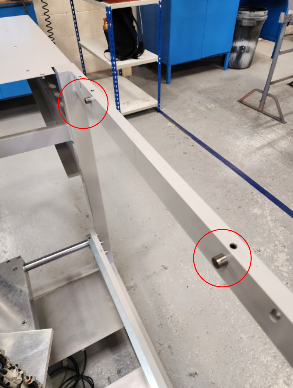
Étape 2 - Add jacking points to frame
Fit 2 off 1/2" x 1" dowels to frame as shown . Ensure dowels are fully seated . Ensure chamfered end of dowel is inserted first
Secure with 2 off M8 x 12 KCP grubscrews
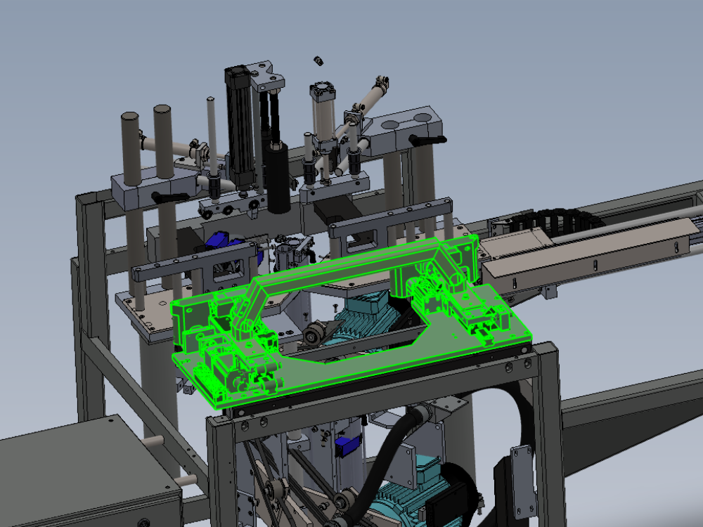
Étape 3 - Mount R0000562 Bench assemble centralise top table
Attach R0000562 Bench assemble centralise top table as shown
Use 4 off M8 x 20 socket caps
Fit assembly at highest position in slots
Dry fit fasteners, apply medium tension


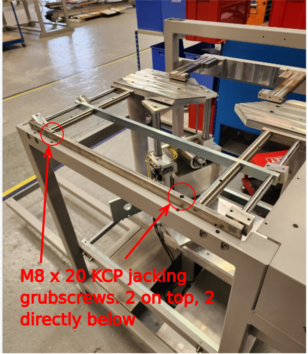
Étape 4 - Add height adjustment points
Add 4 off M8 x 20 KCP grubscrews to points shown .
Adjust grubscrews to touch dowels

Étape 5 - Add squareness adjustment points
Fit 4 off M8 x 12 flat bottomed grubscrews to the points shown
Wind grubscrews to touch frame


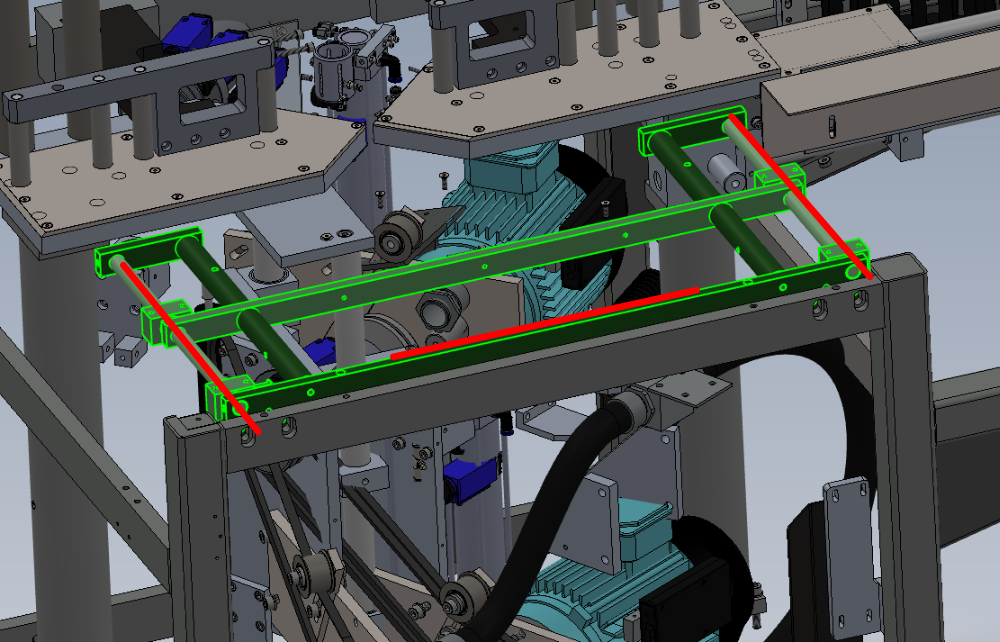
Étape 6 - Adjust position
Set initial position of assembly using engineers level on the indicated axis
Use M8 squareness adjusting grubscrews to set position
Set both positions level


Étape 7 - Fit finger Guard
Fit H0004543 Gap cover saw finger guard to assembly
Use 3 off M5 x 12 socket caps and A form washers
finalise fasteners


Étape 8 - Mount R0015037 Bench assemble SY Assembly
Mount R0015037 Bench assemble SY Assembly
Use 8 off M6 x 20 socket caps
Dry fit fasteners


Étape 9 - Adjust square
Use engineers square to check squareness of front rollers to infeed and outfeed cut tables
Use adjusting grubscrews to set square accurately
Adjusting grubscrews must be set under tension
Only adjust 1 off grubscrew in each pair. Do not jack top table frame away from main frame . 1 point of contact must always be present


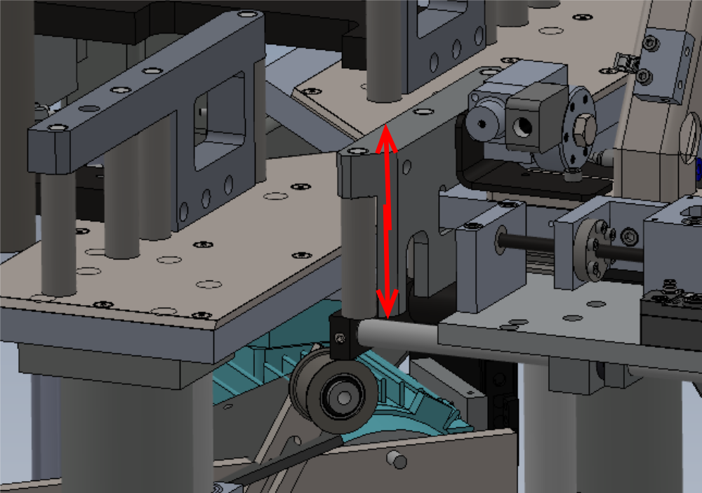
Étape 10 - Adjust Height of Sy assembly
Set height of Sy assembly to cut tables using jacking grubscrews
Release pressure on front 4 off M8 x 20 socket caps
Use M8 x 20 grubscrews to adjust height of assembly
Set to gap of 1.5mm -+ 0.5mm
Ensure assembly sits level/even across all rollers
Apply final tension with adhesive to front M8 x 20 socket caps


Étape 11 - Recheck squareness of rollers
Once height has been adjusted, roller squareness must be checked and reset if movement has occurred . Both height and squareness will have to be manipulated together to achieve all settings to requested specification

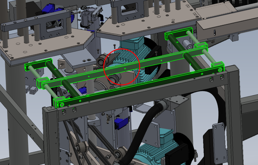
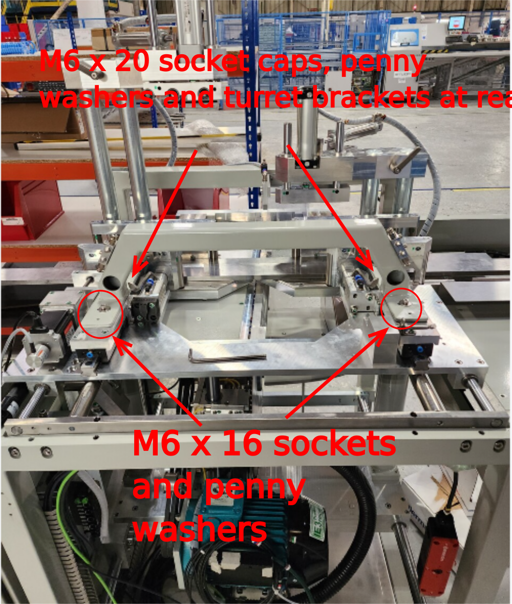
Étape 12 - Attach saddle brace
Attach saddle brace to assembly using 2 off M6 x 16 socket caps 2 off M6 x 20 socket caps all with penny washers
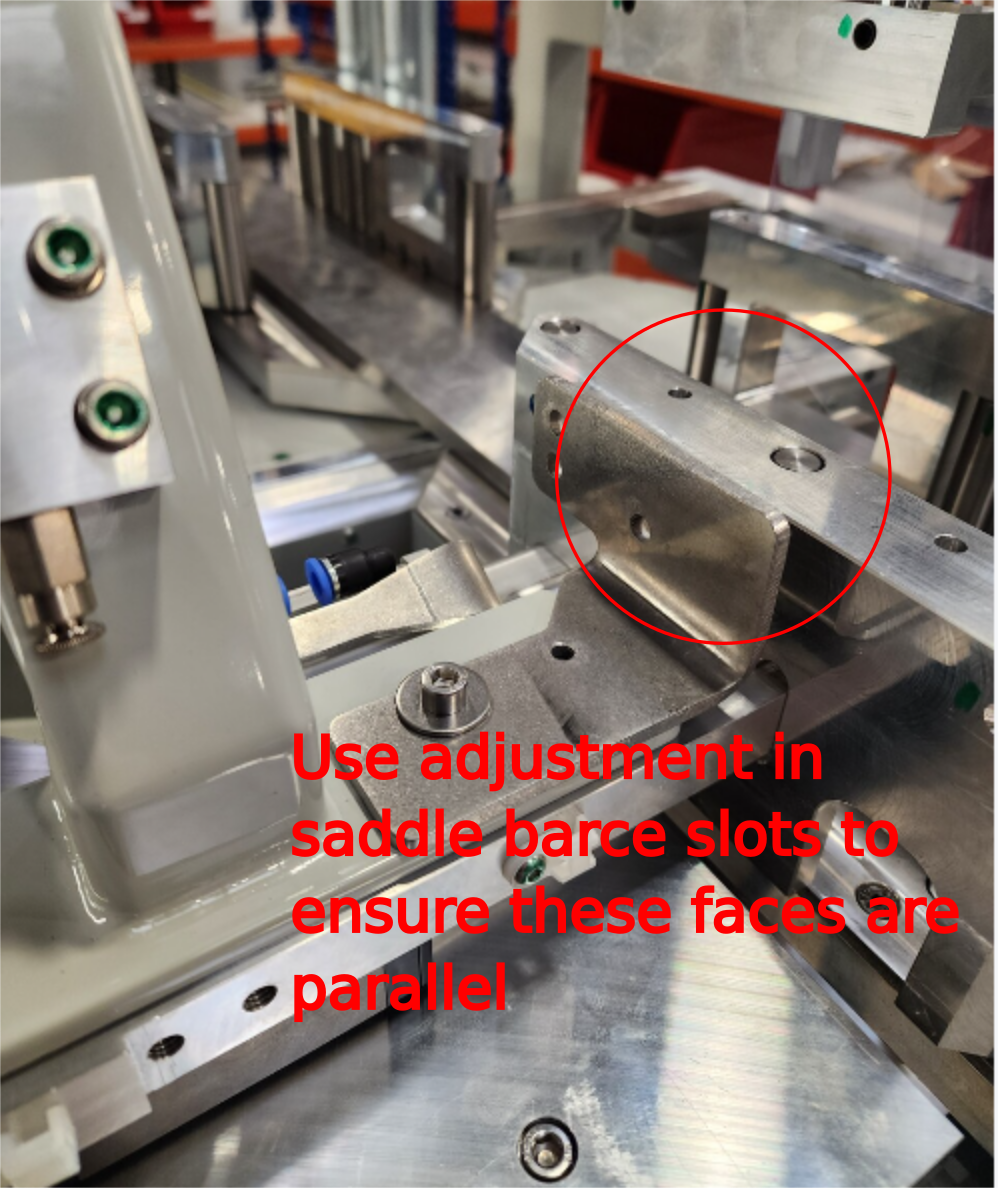
Incorporate turret brackets at rear fixing point when mounting saddle brace
Saddle brace has slots for sideways movement. Utilize this to ensure Z turret brackets sit square in position to fences
Do not apply tension or adhesive to bolts


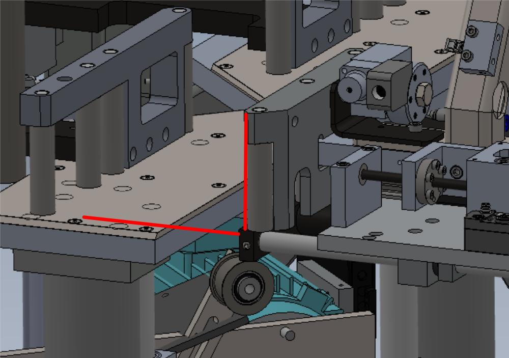
Étape 13 - Set Parallel to backfences
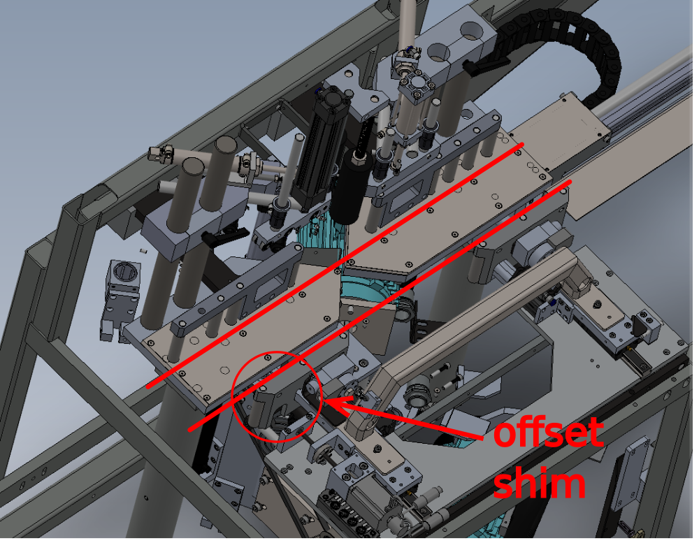
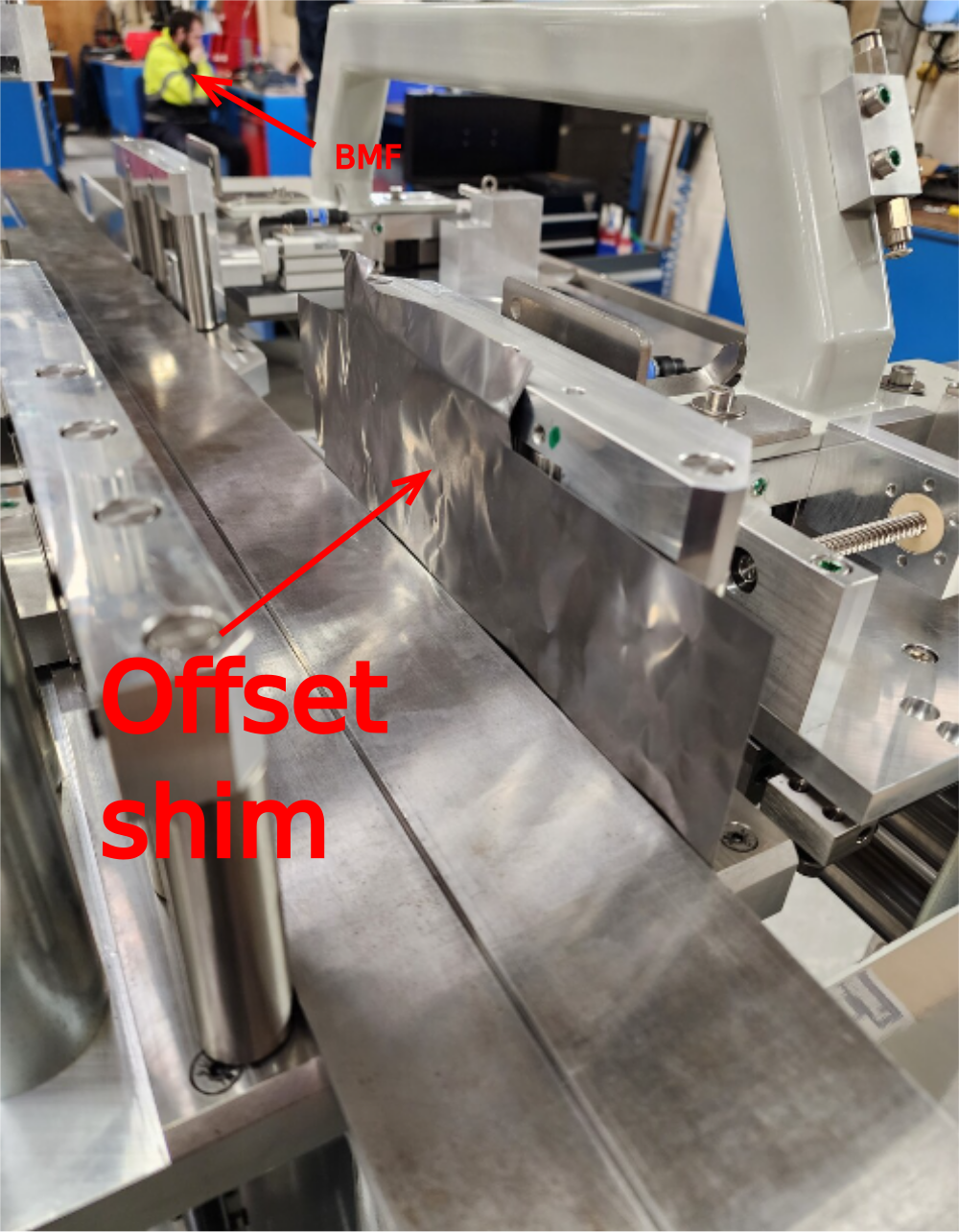
Use 2 off straight edges against back roller fence
Add offset shim of 0.002"/0.05mm to driven side
Set front rollers to touch, using M6 socket caps and counter bore clearance to adjust
Report if unable to achieve parallel from this movement


Étape 14 - Quality check
Check settings are adjusted, check that Z block operation does not foul cut tables
To do this move both z blocks by hand to active and home position and check contact is not made with the cut tables


Étape 15 - Recheck Settings
Recheck all settings once final adjustment has been made
Roller squareness to cut tables
Roller height to cut tables
Parallel to back fences

Étape 16 - Finalise Fasteners
Remove turret brackets ( required for later step of dowelling)
Individually remove and apply adhesive to all dry fasteners and apply final tension


Étape 17 - Recheck settings
Recheck all settings once final adjustment has been made
Roller squareness to cut tables
Roller height to cut tables
Parallel to back fences
Étape 18 - Check adjustment grubscrews
Check that no adjustment grubscrews are loose.
Any grubscrews that are not required should still have adhesive applied and lightly tensioned to set in position


Étape 19 - Dowel Saddle brace
Drill4 off dowel points in saddle brace 5.8mm to a depth of 20mm
Ream to 6mm H7 tolerance
Use 4 off 6mm x 20 dowels to secure


Étape 20 - Recheck settings
Recheck all settings once dowelled to ensure no movement has occurred
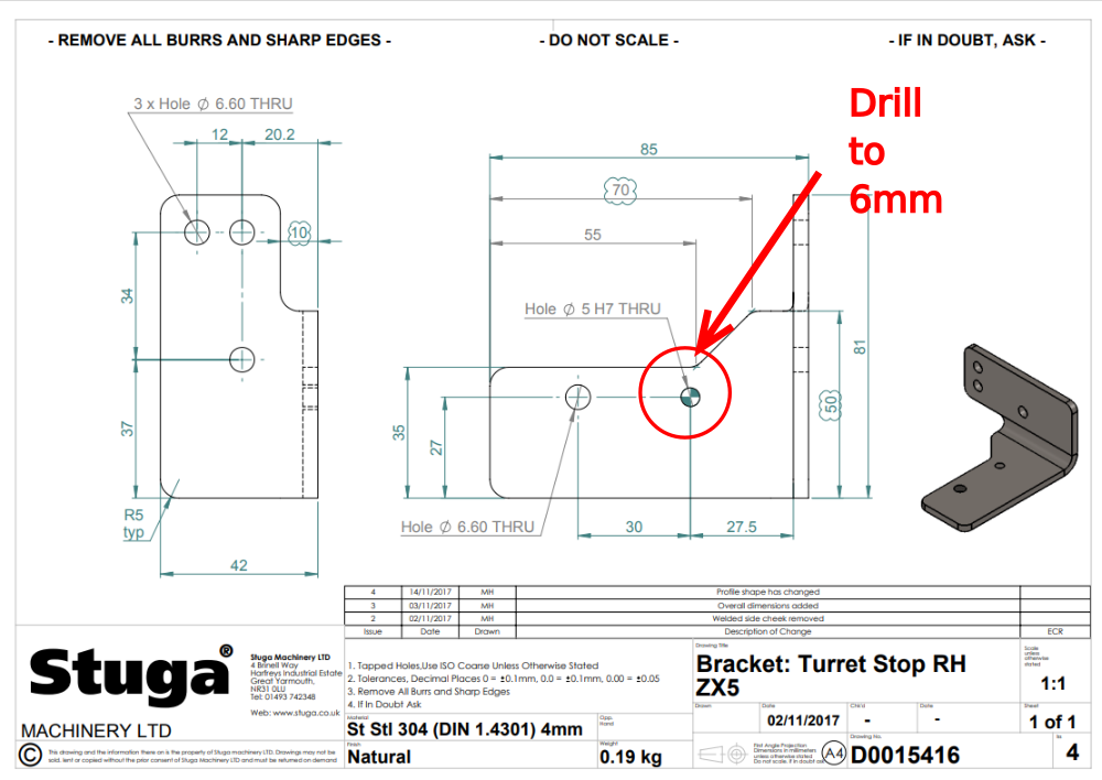
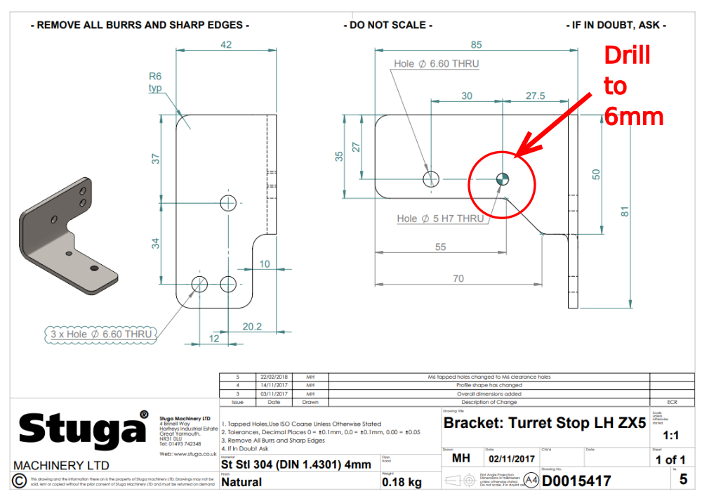
Étape 21 - Amend Turret brackets
Ecr raised 12/12/23 to amend turret bracket D0015416 and D0015417 hole size to 6mm
Amend hole size by hand to 6mm until
Étape 22 - Fit turret stops to brackets
Fit turret assemblies to brackets using 6 off M6 x 16 socket caps and A form washers


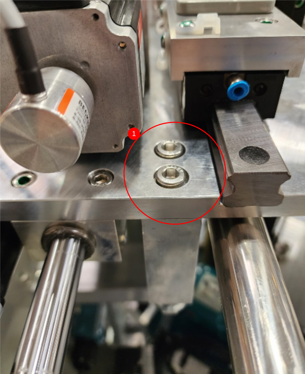
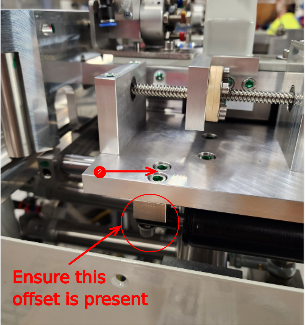
Étape 23 - Fit turret stops to saddle brace
Fit turret stops to saddle braces as shown. Use existing m6 x 20 socket caps and washers to fix. Align over dowels on rear of saddle brace


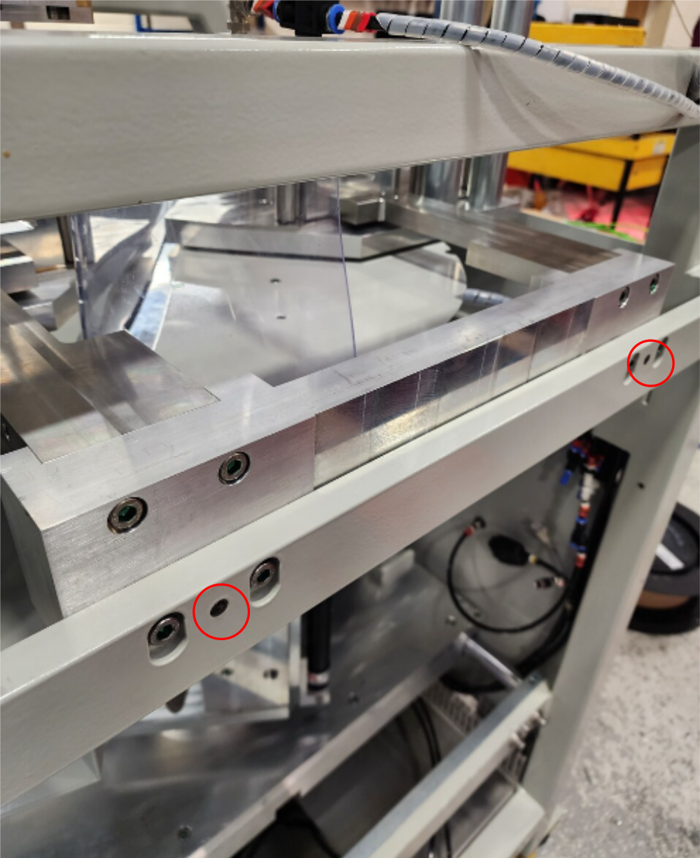
Étape 24 - Dowel lower frame
Drill 4 off holes indicated to 7.8mm through and Ream to 8mm H7
Clean with FE 10
fit 4 off 8mm x 50mm dowels to fix
Add Loctite 270 to dowels


Étape 25 - Dowel backfence
Drill 2 off back fence dowel points to 7.8mm . Drill to 65mm deep to allow flush fitment of dowel
Ream to 8mm H7
Wash out with solvent
Fit 2 off 8mm x 50mm dowels with Loctite 270


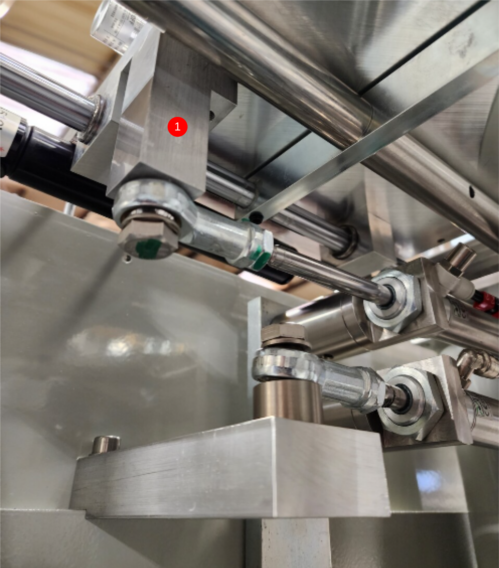
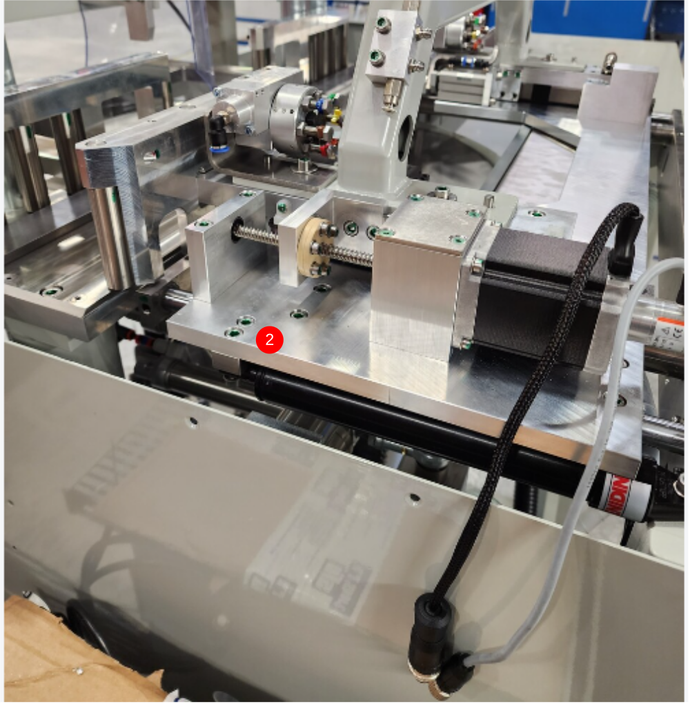
Étape 26 - Connect Damper and cylinder
1 Connect Cylinder mount block with 2 off M8 x 25 socket caps
2 Connect Damper using 2 of M6 x 16 socket caps
Draft
 Français
 English
 Deutsch
 Español
 Italiano
 Português