| [version en cours de rédaction] | [version en cours de rédaction] |
| Ligne 76 : | Ligne 76 : | ||
M0001087 Rubber Bump Stop M6 Ø20x24 x2 | M0001087 Rubber Bump Stop M6 Ø20x24 x2 | ||
| + | |||
| + | P0000010 1/8 6mm elbow x 1 | ||
P0000022 Fitting: Brass Reducing Bush 1/4 - 1/8 BSP x 1 | P0000022 Fitting: Brass Reducing Bush 1/4 - 1/8 BSP x 1 | ||
| Ligne 326 : | Ligne 328 : | ||
3 1 off cylinder fit P0000026 Silencer 1/4 BSP to nose port, and assemble the following components and fit to base port | 3 1 off cylinder fit P0000026 Silencer 1/4 BSP to nose port, and assemble the following components and fit to base port | ||
| + | |||
| + | P0000010 1/8 bsp 6mm elbow x 1 | ||
P0000050 Fitting: Silencer 1/8<nowiki>''</nowiki> BSP x 1 | P0000050 Fitting: Silencer 1/8<nowiki>''</nowiki> BSP x 1 | ||
Version du 27 février 2024 à 12:02
Final assembly details

Difficulté
Difficile
Durée
6 heure(s)
Sommaire
- 1 Introduction
- 2 Étape 1 - Unless otherwise stated
- 3 Étape 2 - Fit Bearing rails
- 4 Étape 3 - Fit Bearings
- 5 Étape 4 - Attach Bearing plates
- 6 Étape 5 - Add Spacer bars
- 7 Étape 6 - Add Vy datum bracket
- 8 Étape 7 - Add hardstops
- 9 Étape 8 - Attach Saw plates
- 10 Étape 9 - Attach motor assemblies
- 11 Étape 10 - Attach Saw plates
- 12 Étape 11 - Attach motor assemblies
- 13 Étape 12 - Attach link assembly
- 14 Étape 13 - Assemble lift cylinders
- 15 Étape 14 - Attach cylinders
- 16 Étape 15 - Add Hard Stops
- 17 Étape 16 - Fit VY drive motor assembly
- 18 Commentaires
Introduction
Tools Required
Standard Hex key set
Standard Spanner set
ZX5 Blade tightening tool
Compressed air connection with regulation (for axis support)
Parts required
A0001069 Energy Chain Series B15.050 (48mm radius) Openable x 2
A0001070 Igus Mounting Br Set for A0001069 Non-Pivot x 2
B0000046 Slide Base Bearing Block (Straight Grease Nipple) x 4
B0000173 Blanking plug foc x 28
B0000426 Linear Rail MSB25 400mm Long (AMT) x 4
D0015156 Saw Bearing Plate x 2
D0015161 Saw Plate x 4
D0015162 Saw Mid Spacer Bar x 1
D0015163 Saw Bearing Spacer Bar x 1
D0015168B Balance Cylinder Bracket x 2
D0015169B Cylinder Rod Bracket x 2
D0015179 Energy Chain Bracket x 2
D0015180 Datum Switch Bracket (VZ) x 1
D0015183 VY Stop x 2
D0015235 VY Datum Switch Bracket x 1
D0015236 VY Energy Chain Bracket - Fixed x 1
D0015237 VY Energy Chain Bracket - Moving x 1
D0015250 Safe Sensor Block x 1
D0015251 Safe Sensor Finger x 1
D0015440 Spacer: Ø12.7 x 36, M6 tap thru x 2
D0015452 Scissor Cable Retainer x 1
D0015541 Energy Chain Deflector x 1
D0015704 Energy Chain Support Plate x 1
E0000336 Sensor: M8; 2mm, PNP N/O, M8 conn x 2
E0001185 Elte Saw motor x 4
M0001087 Rubber Bump Stop M6 Ø20x24 x2
P0000010 1/8 6mm elbow x 1
P0000022 Fitting: Brass Reducing Bush 1/4 - 1/8 BSP x 1
P0000023 Fitting: Hex Nipple 1/8 BSP x 1
P0000026 Silencer 1/4 BSP x 1
P0000050 Fitting: Silencer 1/8'' BSP x 1
P0000077 Straight Adaptor 8mm - 1/8BSP x 1
P0000140 Fitting: Quick Exhaust Valve 1/8" x 1
P0001040 Fitting: 1/8BSP Hex Head Silencer x 2
P0001041 SMC Reed Switch Mounting Bracket BJ3-1 x 2
P0001133 Cylinder: Ø50 x 500 x 2
P0001134 Floating Joint M18x1.5 x 2
P0001140 Pilot Check Valve: 8mm to 1/4" BSP x 2
P0001141 Fitting: SMC Flow Controller Elbow Ø8-1/4BSP x 1
P0001142 Adjustable Damper 150mm stroke (3000N) x 1
P0001144 Reed Switch Mounting Band for Ø50 cyl x 2
R0015084 Bench assemble and Drill Off Swarf chutes
V0000028B-ZX5 Notching Blade: Ø300 x 96 teeth x 2.8mm pl x 3.3mm kf x24mm x 4
Étape 1 - Unless otherwise stated
Use locktite 243 on all fasteners
Use loctite 572 on all threaded pneumatic connection
Pen mark all fasteners to show finalised

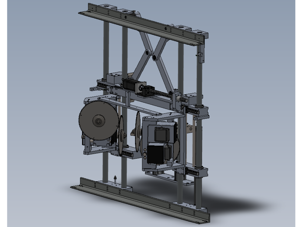
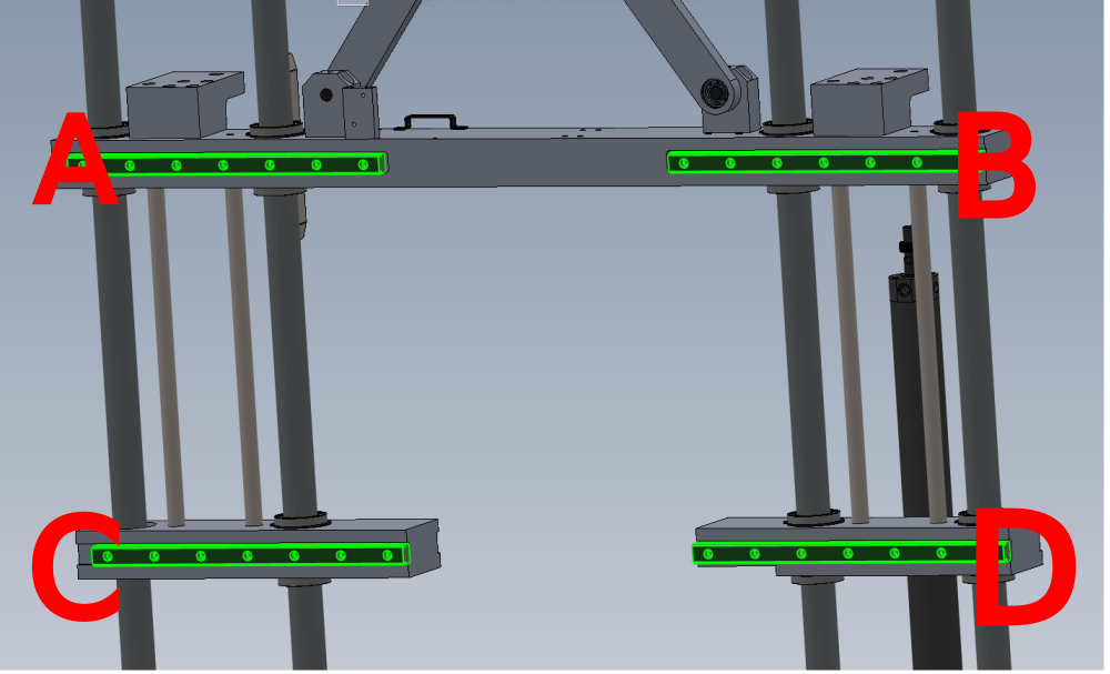
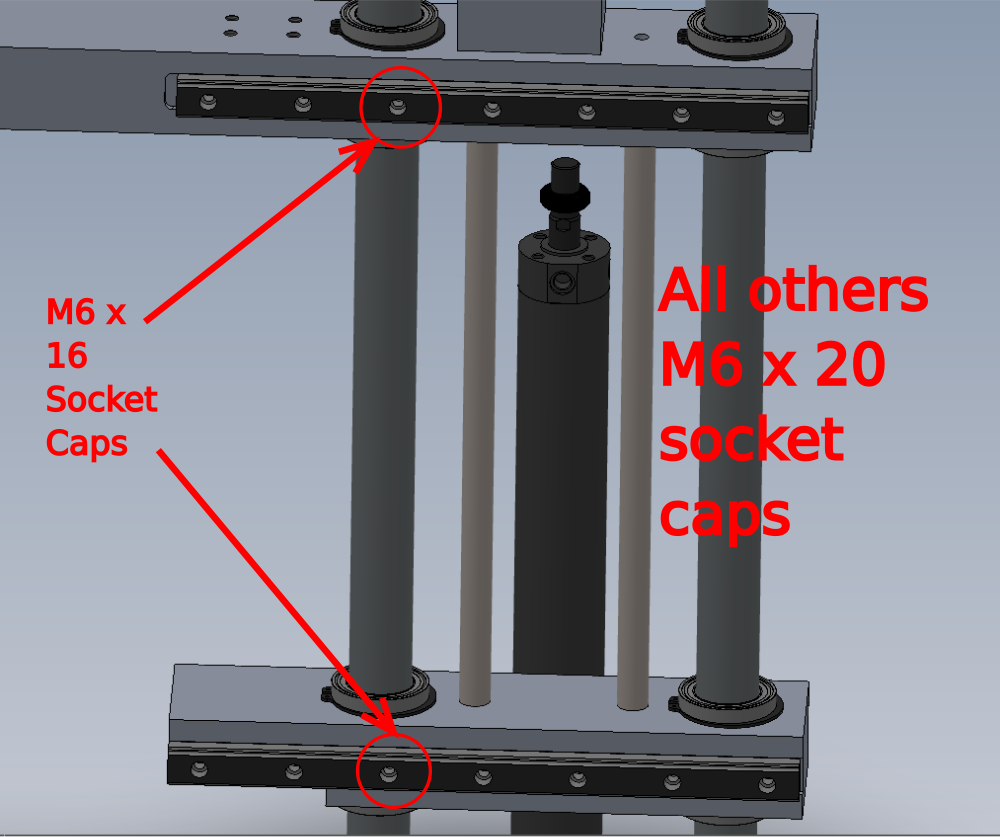
Étape 2 - Fit Bearing rails
Fit 4 off B0000426 Linear Rail MSB25 400mm Long as shown
A and B can be finalised with fixings, C and D should be left loose for adjustment later
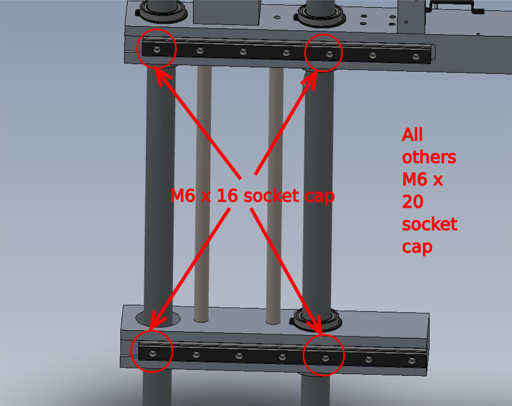
Use M6 x 20 and M6 x 16 socket caps at indicated points
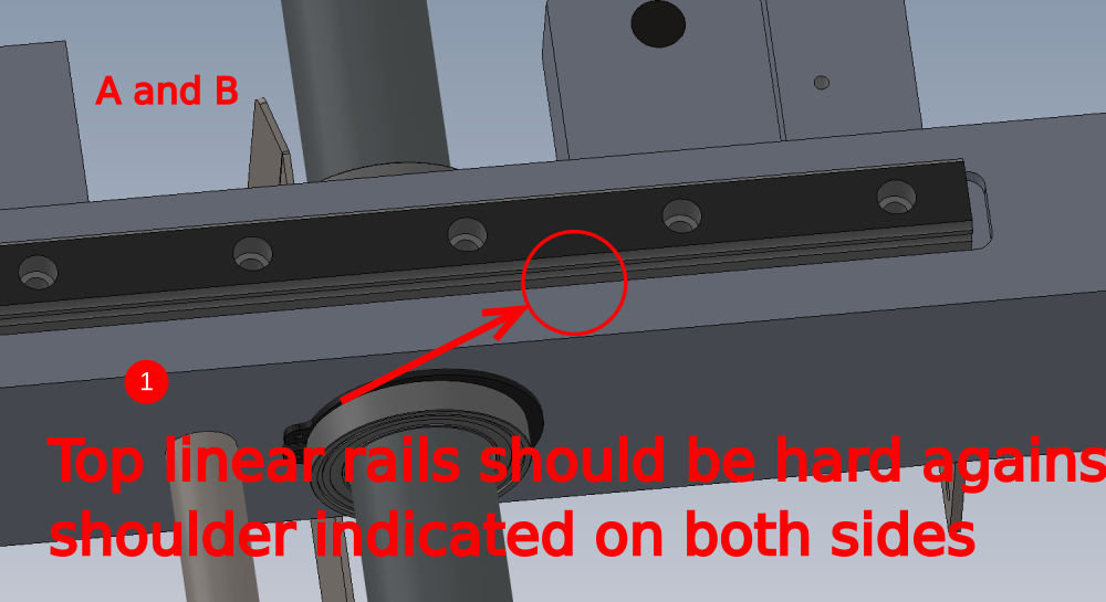
Take care on the following notes as shown
1 Ensure correct witness faces are used
2 Correct fasteners are used at correct positions
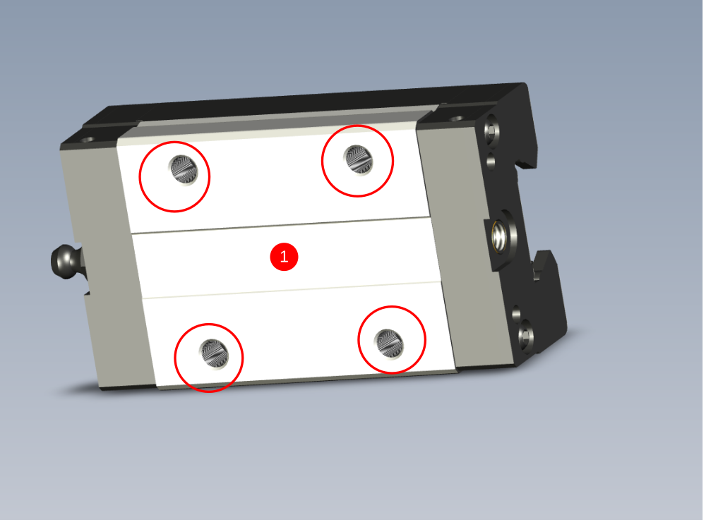
Étape 3 - Fit Bearings
1 Thoroughly degrease B0000046 Slide Base Bearing Block fixing holes with FE10 solvent
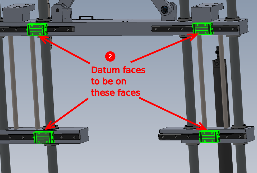
2 Fit bearings to rails as shown. Ensure bearing datum face in orientated as shown
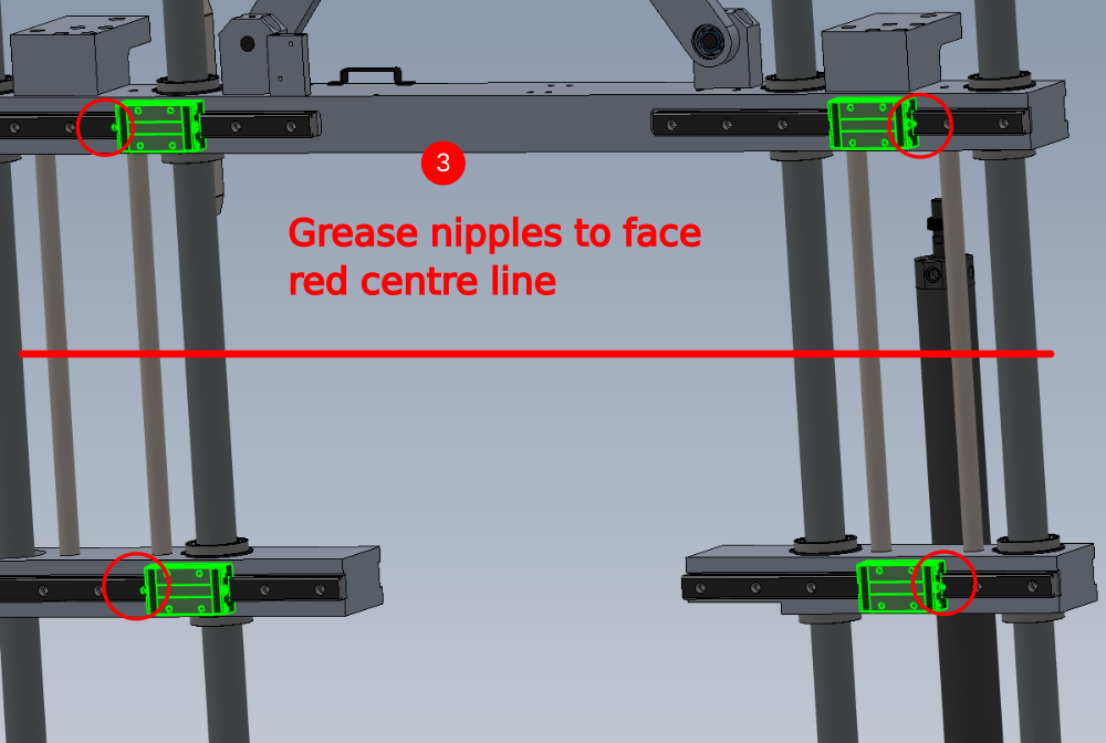
3 Slide Bearing to end of rails and fit supplied grease nipple and orientate as shown
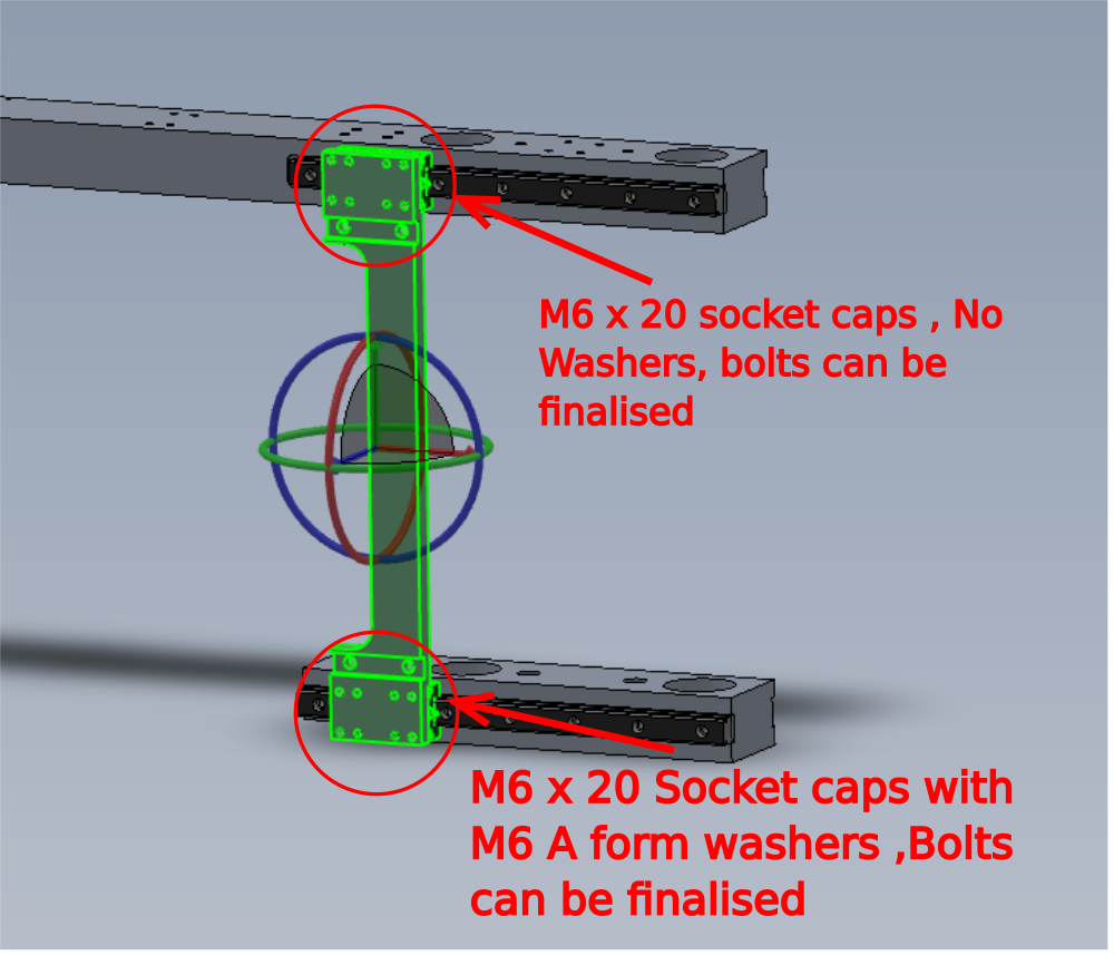
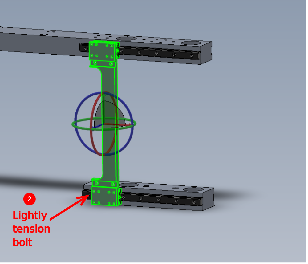
Étape 4 - Attach Bearing plates
Attach 2 off D0015156 Saw Bearing Plate as shown, using fixings indicated
Observe following points
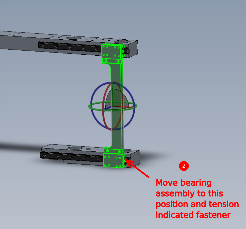
1 Ensure bearings are mated correctly to register on bearing block as shown
2 Use bearing plate with correctly mounted bearings to set position on lower bearing rail. Ensure rail position is set by bearing rail at both ends of travel
3 Finalise all Fasteners in lower bearing rail , adding adhesive and tension individually
4 Insert 28 off B0000173 blanking plug to linear rails. Ensure plugs are fitted accurately flush to top face of rail

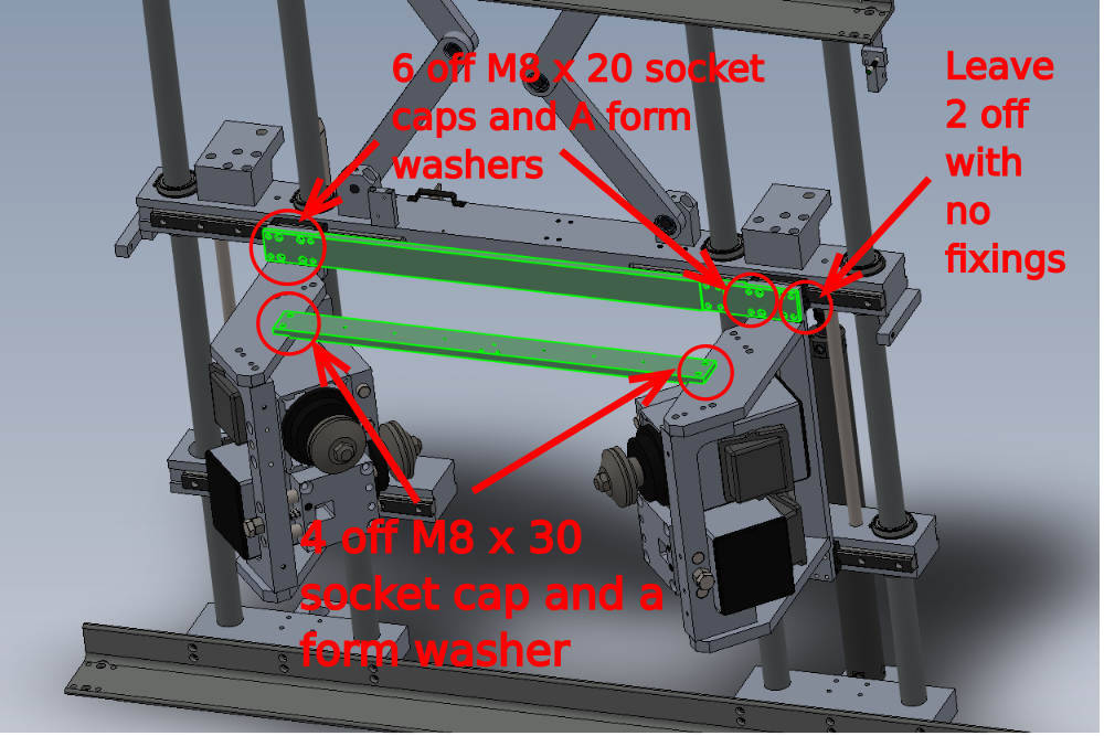
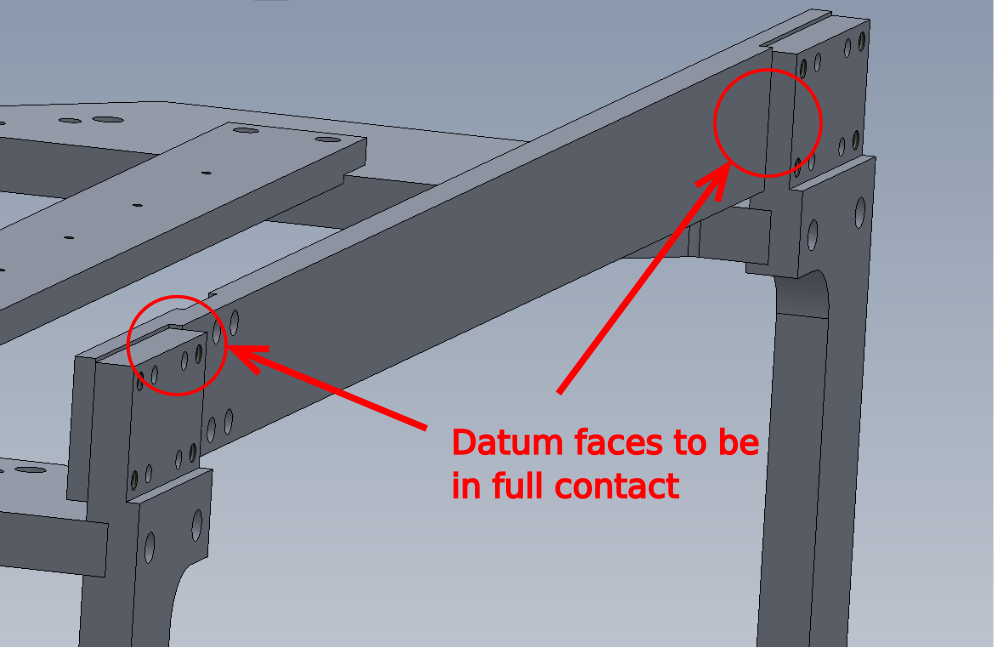
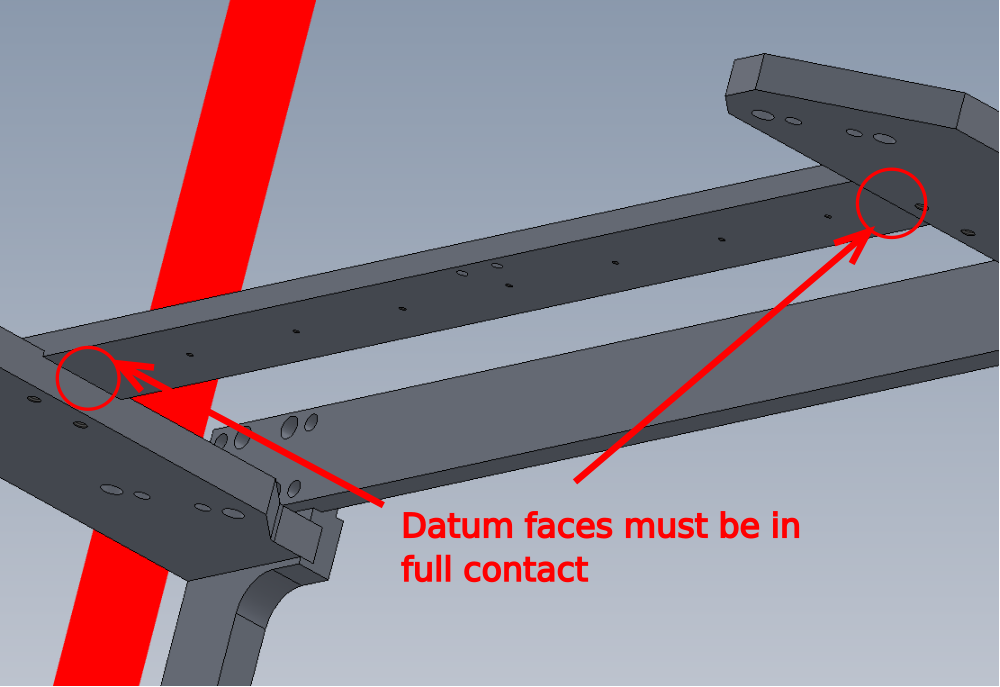
Étape 5 - Add Spacer bars
Fit D0015162 Saw Mid Spacer Bar x 1 and D0015163 Saw Bearing Spacer Bar as shown
Ensure Datum faces are contacting as shown on both bars
Étape 6 - Add Vy datum bracket
1 Fit D0015235 VY Datum Switch Bracket as shown along with D0015251 Safe Sensor Finger
Note. This assembly always fits to the rear of the v notch assembly (for handing orientation )
2 Set E0000336 sensor as shown. Set to minus 1mm to face of bearing rail
Ensure locking nut for sensor is not over tightened as damage can be caused to sensor
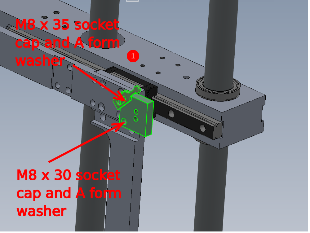
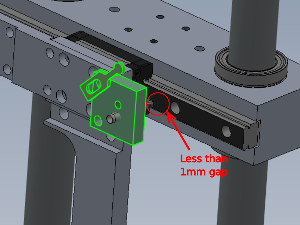
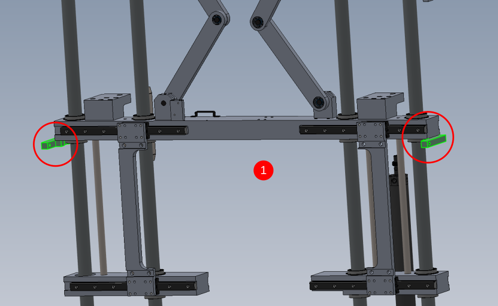
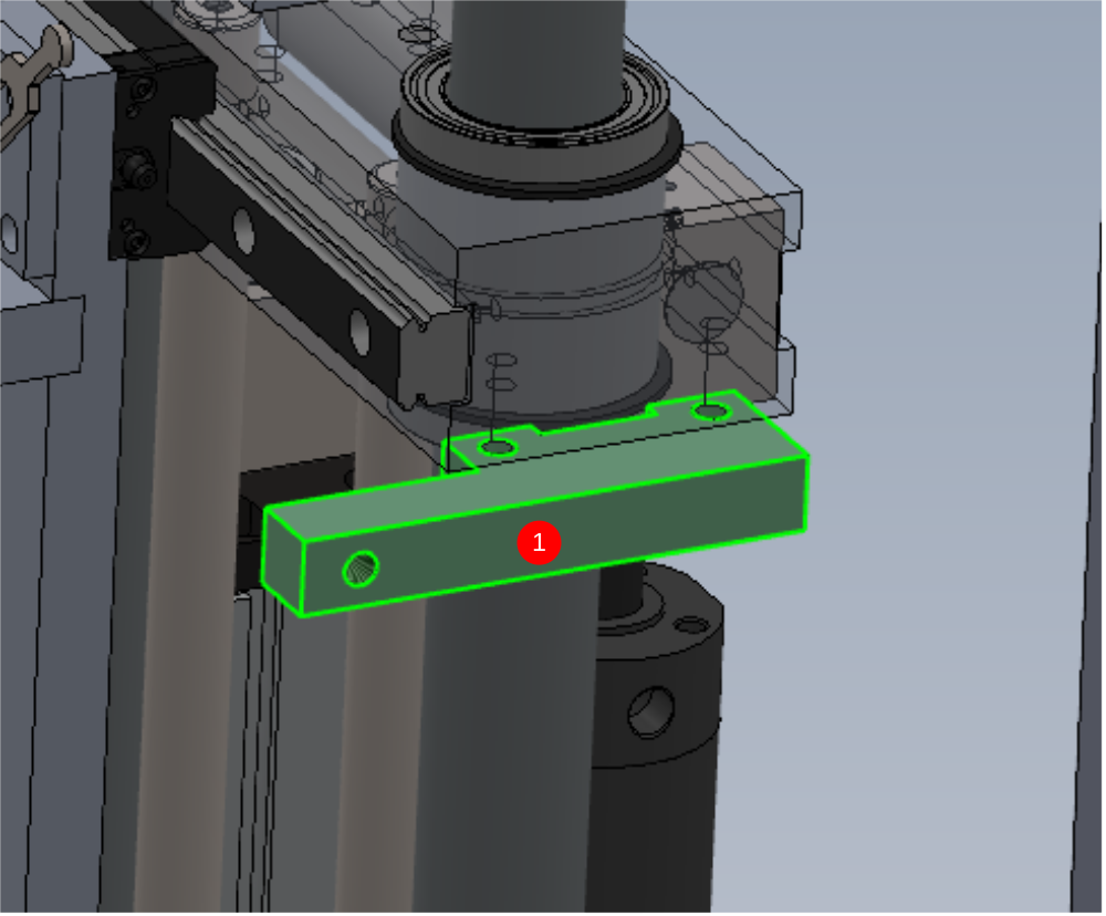
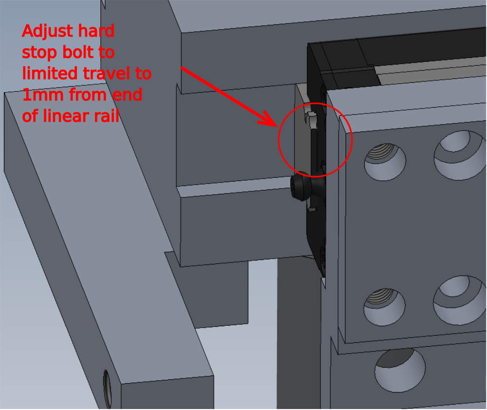
Étape 7 - Add hardstops
1 Fit 2 off D0015183 VY Stop as shown. Fix with M8x 30 socket caps and A form washers and orientate as shown
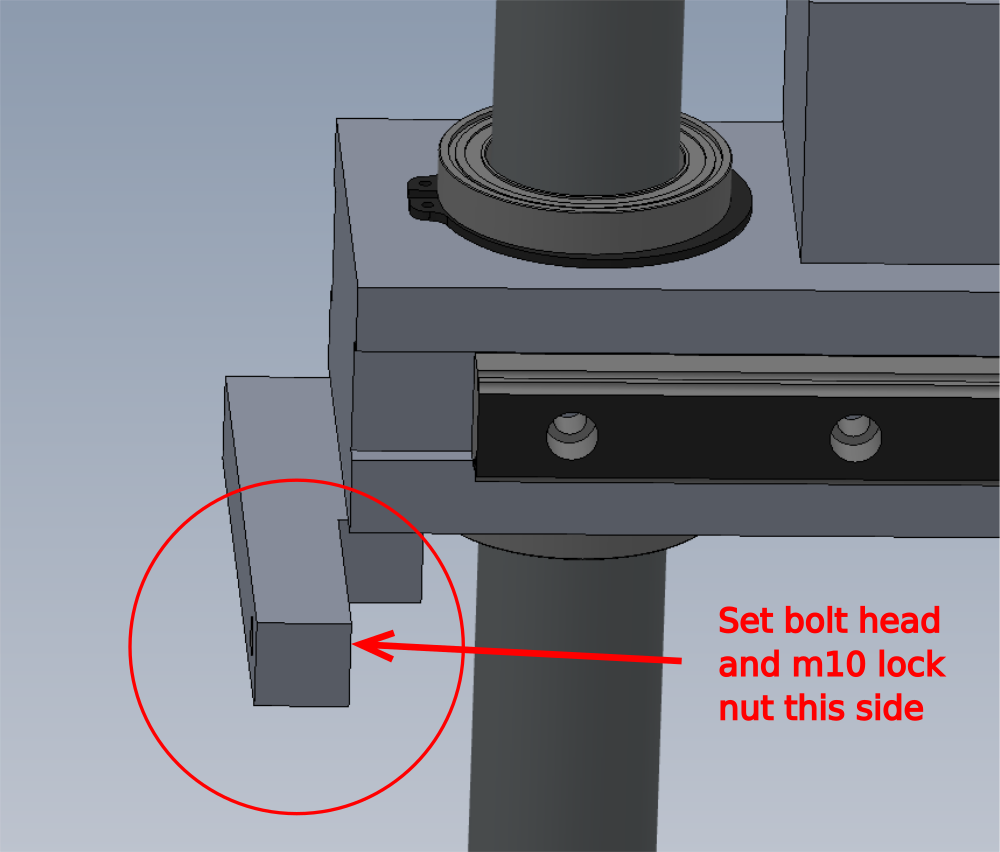
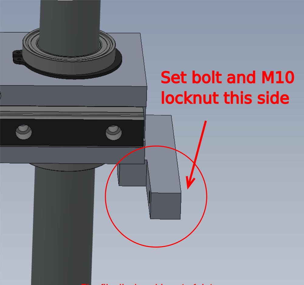
2 Fit M10 x 50 set bolt and M10 nut as indicated.
3 Set position. Adjust hard stop to achieve indicated position
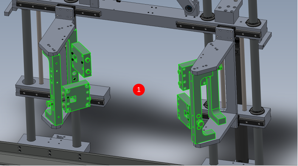
Étape 8 - Attach Saw plates
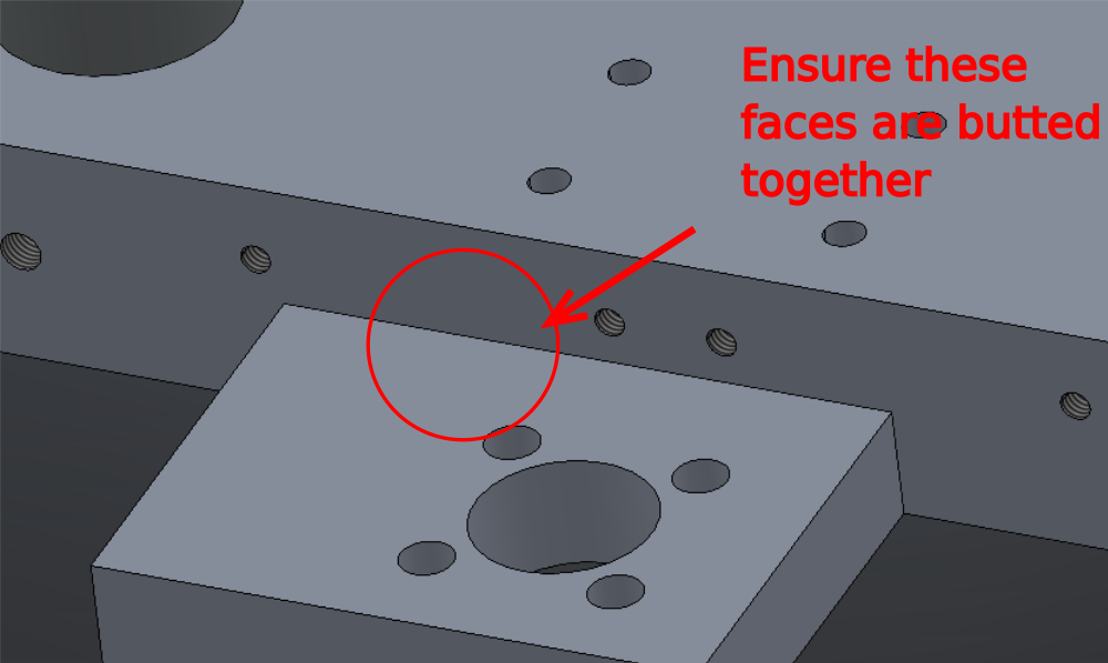
1 Attach as shown 4 off D0015161 Saw Plate , using 2 off M10 x 30 socket caps and A form washers to fix
2 Ensure indicated faces are set flush
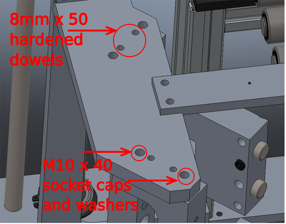
Étape 9 - Attach motor assemblies
1 Attach 4 off pre build motor supports. Orientate as shown
2 Fix using 4 off M10 x 40 socket caps and A form washers, and 4 off 8mm x 50 hardened dowels per saw plate
Étape 10 - Attach Saw plates
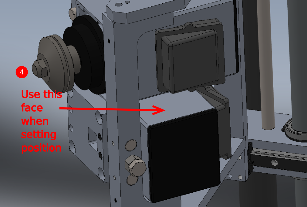
1 Attach as shown 4 off D0015161 Saw Plate , using 2 off M10 x 30 socket caps and A form washers to fix
2 Ensure indicated faces are set flush
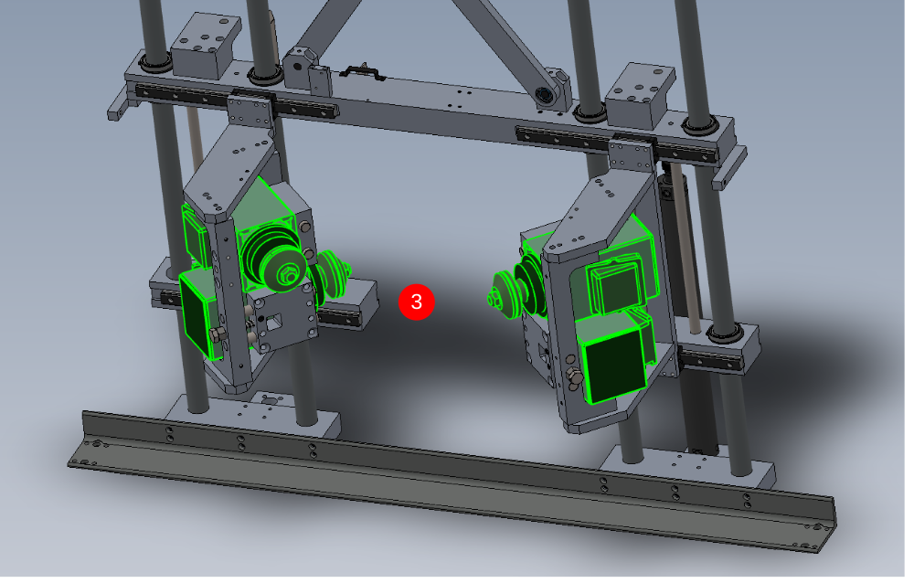
Étape 11 - Attach motor assemblies
1 Attach 4 off pre build motor supports. Orientate as shown
2 Fix using 4 off M10 x 40 socket caps and A form washers, and 4 off 8mm x 50 hardened dowels per saw plate
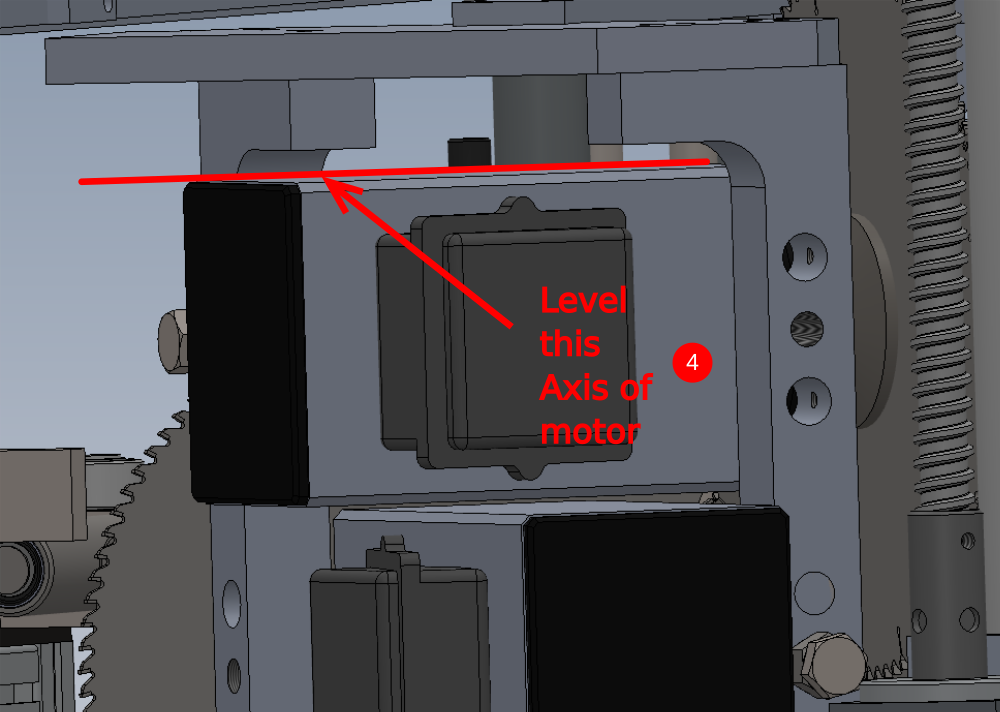
3 Fit 4 off E0001185 Elte Saw motor as shown using 4 off M10 x 50 socket countersunk bolts per motor
4 Ensure motor is set level using engineers level on the indicated axis as shown when fitting motors
Étape 12 - Attach link assembly
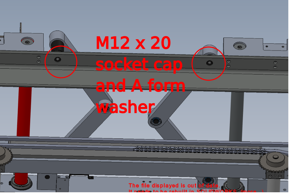
1 Use 2 off M12 x 20 socket caps with M12 A form washers and fix where shown
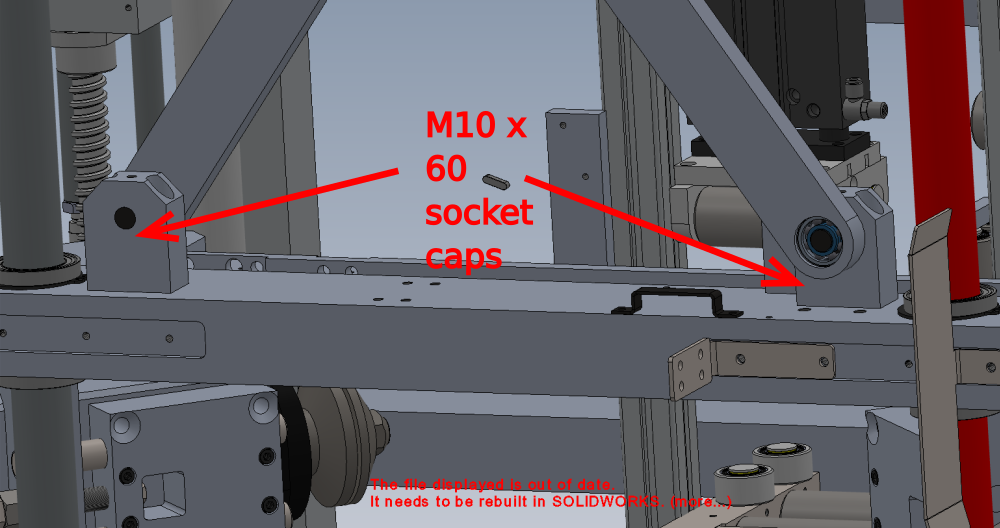
2 Fit lower brackets with 4 off M10 x 60 socket caps
3 Attach P0001142 Adjustable Damper 150mm stroke 1 off. Fix with 2 off M8 x 40 socket caps and A form washers to Suit to position damper central . Bolt will also require cutting to ensure correct spacing ( See Scott)
(Pictures and info required )

Étape 13 - Assemble lift cylinders
Photos required of these steps please
1 Fit 2 off P0001134 Floating Joint M18x1.5 to 2 off P0001133 Cylinder: Ø50 x 500
2 1 off cylinder fit P0001141 Fitting: SMC Flow Controller Elbow Ø8-1/4BSP to nose port , and 1 off P0001140 Pilot Check Valve: 8mm to 1/4" BSP to base port. Fit additional air fitting to check valve (P0000010?)
3 1 off cylinder fit P0000026 Silencer 1/4 BSP to nose port, and assemble the following components and fit to base port
P0000010 1/8 bsp 6mm elbow x 1
P0000050 Fitting: Silencer 1/8'' BSP x 1
P0000077 Straight Adaptor 8mm - 1/8BSP x 1
P0000140 Fitting: Quick Exhaust Valve 1/8" x 1
P0000022 Fitting: Brass Reducing Bush 1/4 - 1/8 BSP x 1
P0000023 Fitting: Hex Nipple 1/8 BSP x 1
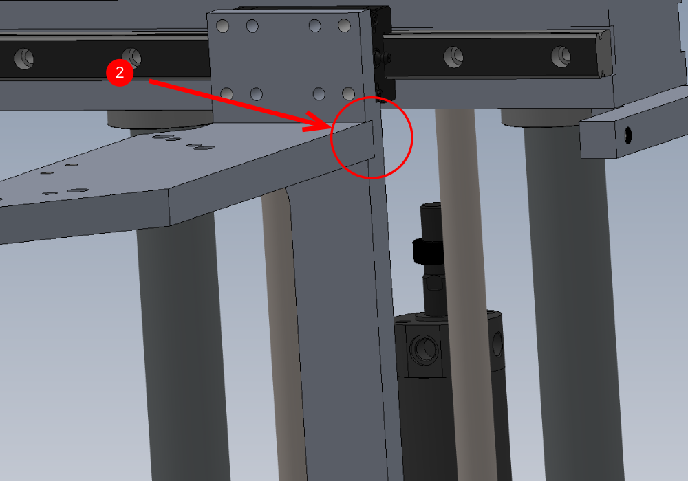
Étape 14 - Attach cylinders
Photos required
1 Attach 2 off D0015168B Balance Cylinder Bracket x 2 as shown. Fix with 8 off M8 x 30 socket caps.
2 Attach cylinders to brackets using 8 off M8 x 30 socket caps and A form washers
Cylinder with flow restrictors to be fitted to front of machine, cylinder with quick exhaust to be fitted to rear of machine.
3 Use P0000401 to connect to cylinder check valve and purge to disable check lock and allow movement
4 Attach cylinders to top mounts (pictures required)
5 Connect air to cylinders to lift V notch assembly to maximum up position
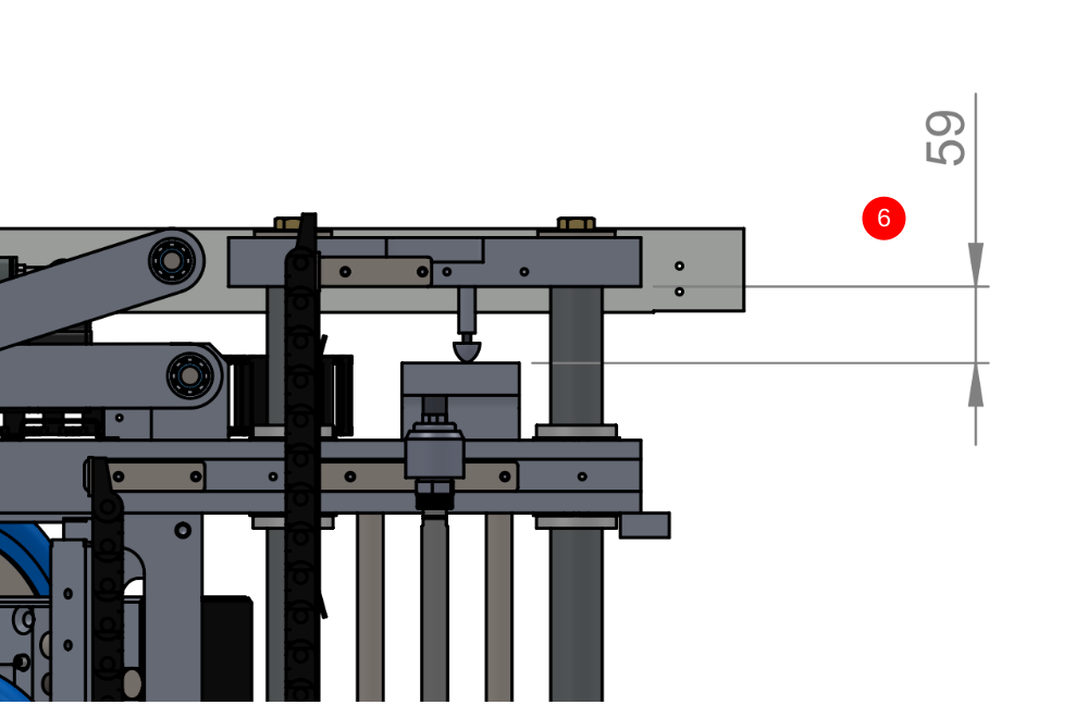
6 Adjust cylinder stroke into floating knuckle and floating knuckle into mount block to achieve measurement indicated of 59mm. Set both sides to this measurement . Ensure thread is evenly distributed between both components when adjusting (photo required)

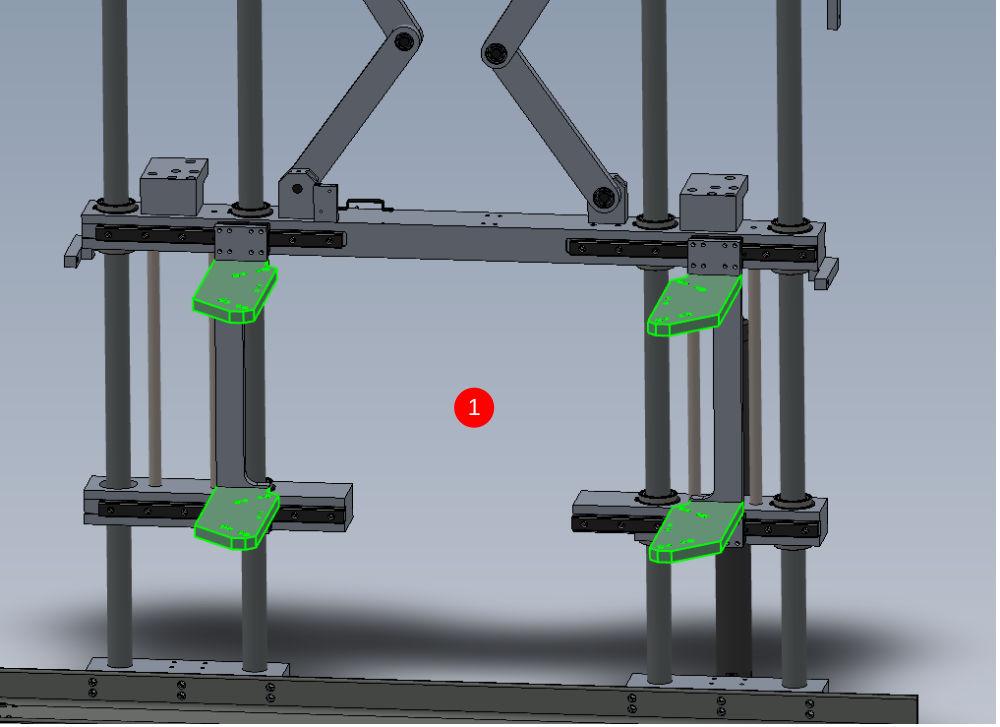
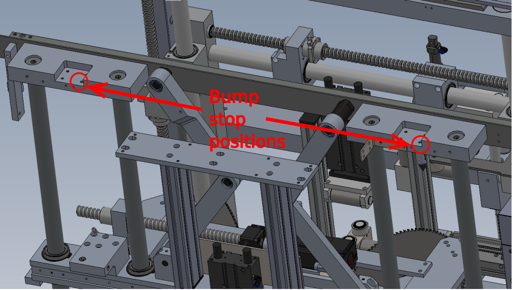
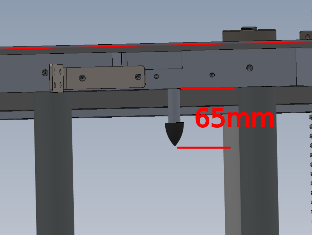
Étape 15 - Add Hard Stops
Pictures required
Assemble 2 off M0001087 Rubber Bump Stop M6 Ø20x24 with D0015440 Spacer: Ø12.7 x 36, M6 tap thru adding M6 nut for locking
With v notch assembly lowered, Fit assembled bump stops to positions shown
Attach with M6 x 35 socket caps and M6 heavy washer
Set to shown measurement of 65mm
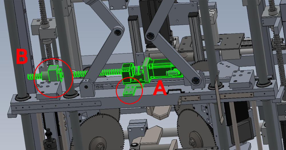
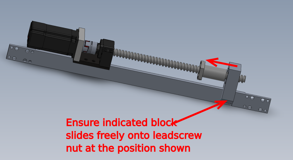
Étape 16 - Fit VY drive motor assembly
Attach assembly as shown
Secure using 4 off M8 x 30 socket caps With A form washers at point A
Secure Point B with 2 off M8 x 25 socket caps and A form washers
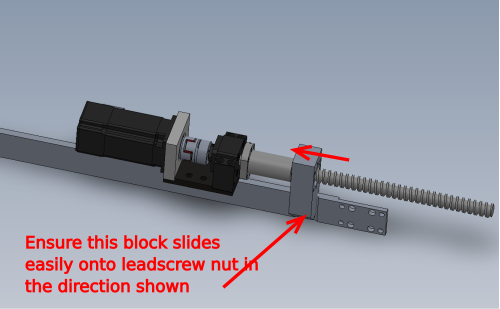
Correct alignment Check .
Alignment between leadscrew nut and mounting block are vital. To check alignment , remove fasteners holding leadscrew nut in place, and wind out nut from housing . Check in multiple positions on axis that leadscrew nut enters block correctly and is inline with the bore
Draft
 Français
 English
 Deutsch
 Español
 Italiano
 Português