| [version en cours de rédaction] | [version en cours de rédaction] |
| Ligne 5 : | Ligne 5 : | ||
|Categories=Production | |Categories=Production | ||
|Difficulty=Hard | |Difficulty=Hard | ||
| − | |Duration= | + | |Duration=4 |
|Duration-type=hour(s) | |Duration-type=hour(s) | ||
}} | }} | ||
Version actuelle datée du 3 avril 2024 à 12:19
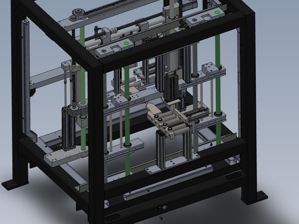
Alignment criteria for v notch sub frame

Difficulté
Difficile
Durée
4 heure(s)
Sommaire
- 1 Introduction
- 2 Étape 1 - Unless otherwise stated
- 3 Étape 2 - Set Top mount Parallel
- 4 Étape 3 - Measure offset
- 5 Étape 4 - Adjust bottom mount
- 6 Étape 5 - Level Lower mount
- 7 Étape 6 - Finalise Fasteners
- 8 Étape 7 - Adjust Vertical
- 9 Étape 8 - Double Check
- 10 Étape 9 - Squareness Check
- 11 Étape 10 - Sign off
- 12 Étape 11 - Final fixings
- 13 Étape 12 - Add Thread lock
- 14 Commentaires
Introduction
Tools Required
2 off 2 meter straight edge
1 meter straight edge
Engineers level
Engineers 12" square
Feeler gauges
Standard hex key set
Standard HSS drill set
Standard tap set
Clamp blocks
600m steel rule
Vernier
300mm parallels
1" parallels
Parts required
Étape 1 - Unless otherwise stated
Use locktite 243 on all fasteners
Use loctite 572 on all threaded pneumatic connection
Pen mark all fasteners to show finalised

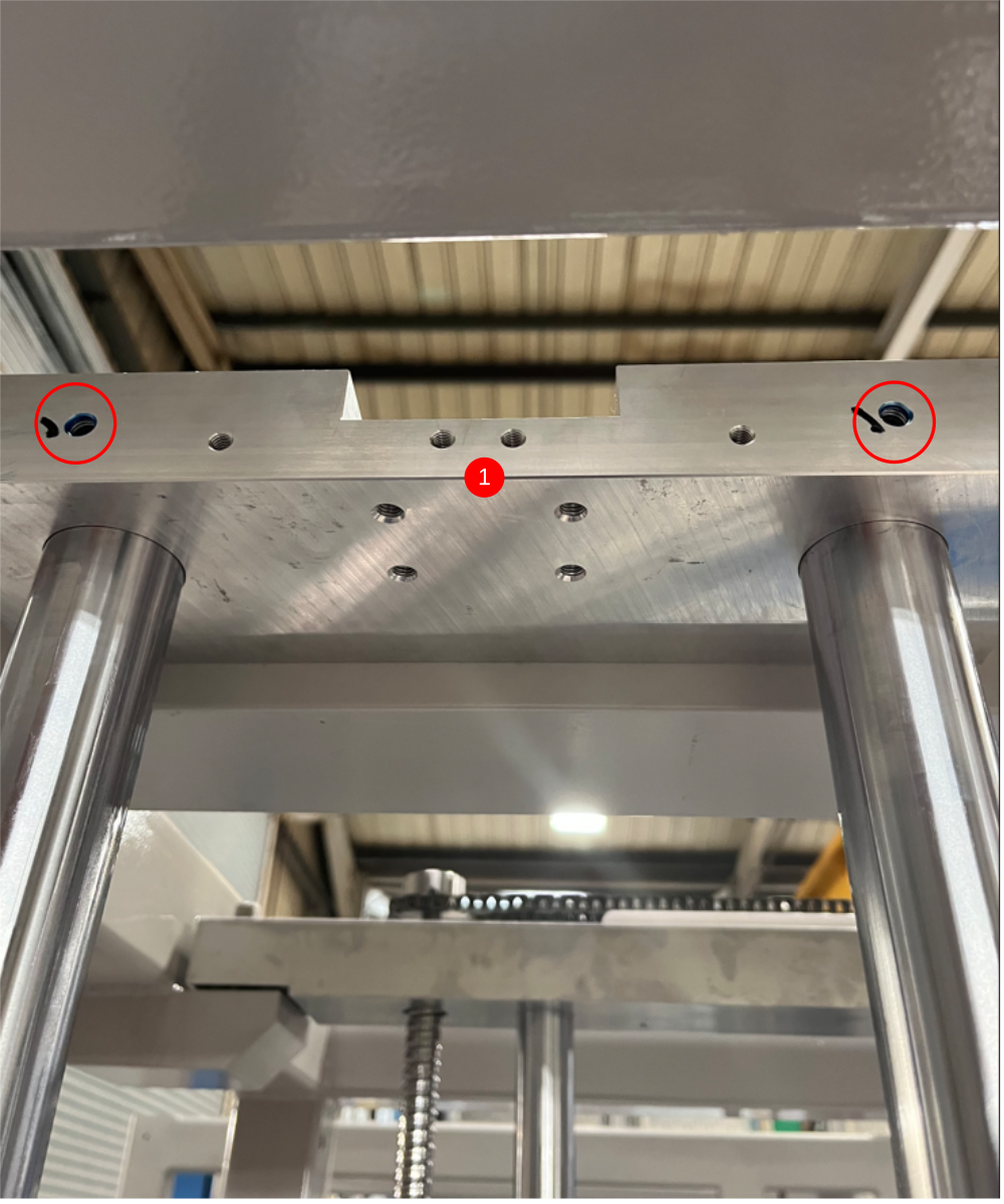
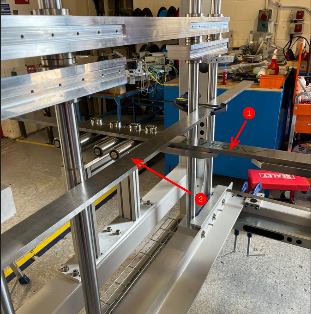
Étape 2 - Set Top mount Parallel
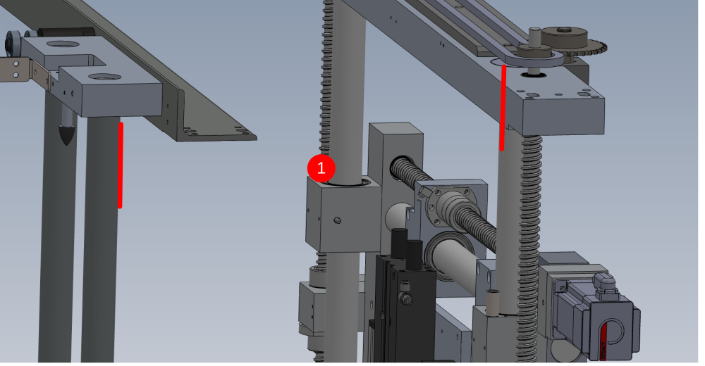
Set top beam mount parallel to ring subframe
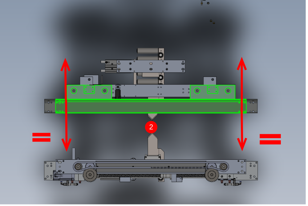
1 Measure indicated points both sides
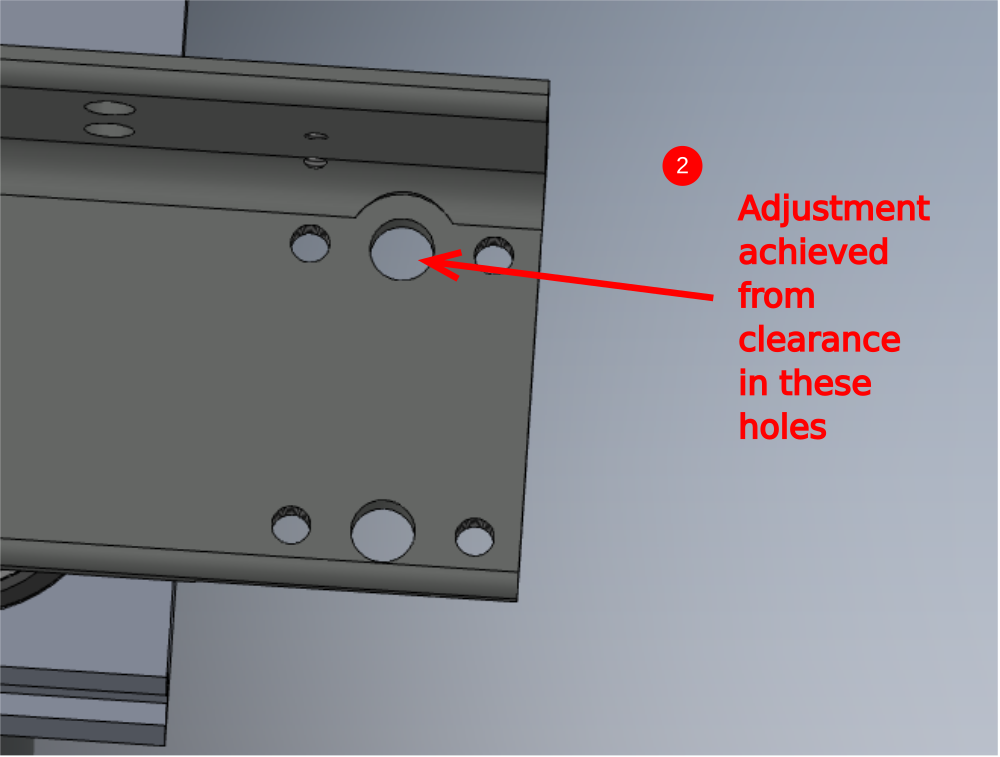
2 Adjust in directions shown to set both measurements to match . release M12 fasteners indicated and adjust using clearance in holes
Take note of measurement set to. Accuracy of +- 0.25mm


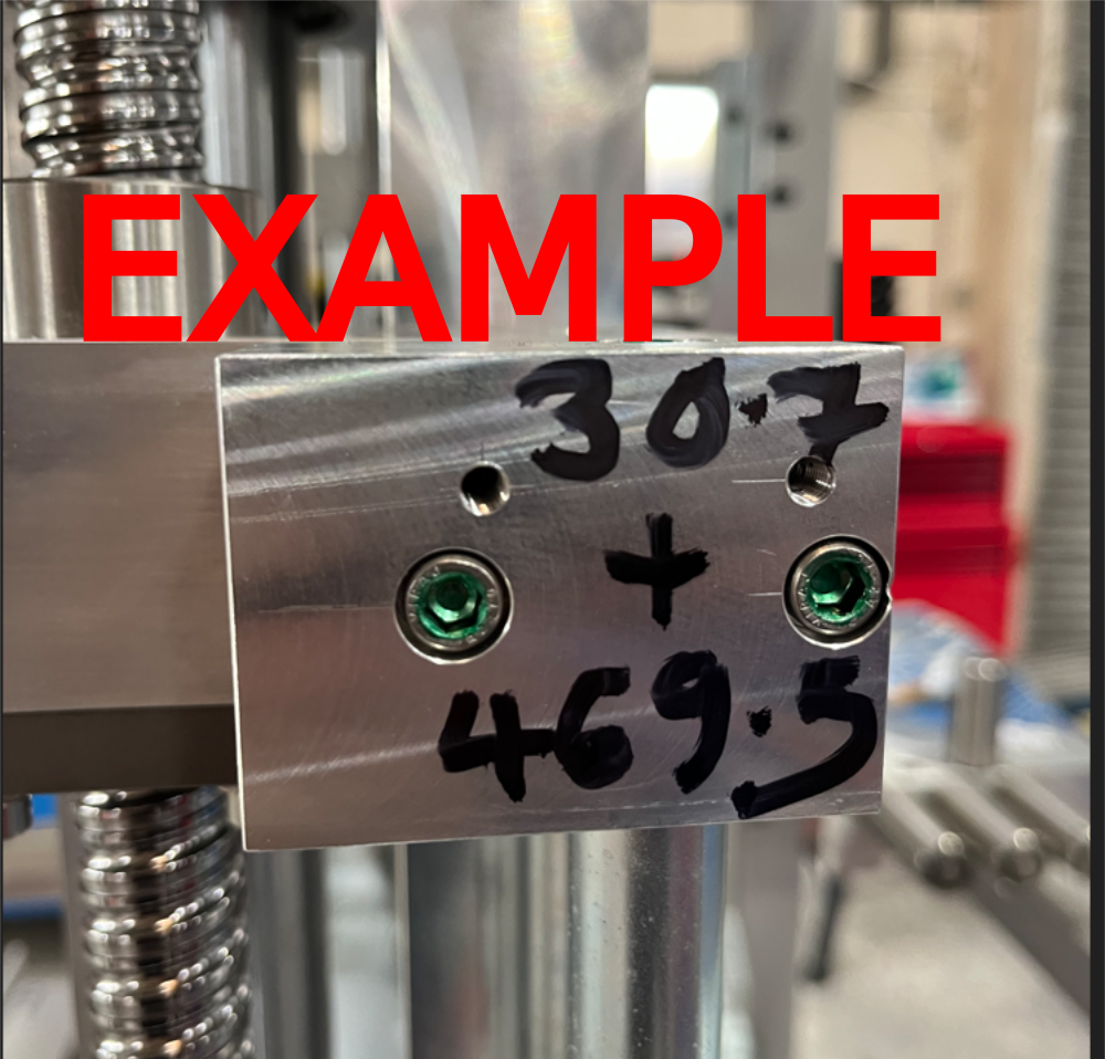
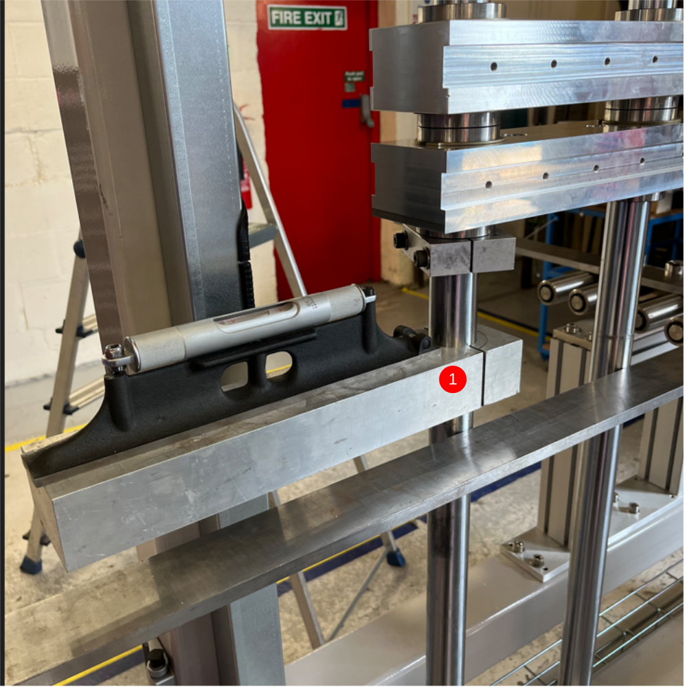
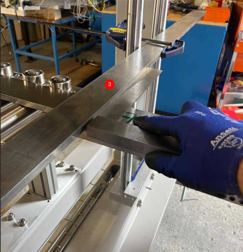
Étape 3 - Measure offset
Measure distance from shaft to front face of beam mount as shown using vernier
Check both sides are consistent
Calculate new measurement by adding step 2 measurement to vernier measurement
for example 30.7mm (vernier measurement0+ 469.5mm (parallel set measurement) = 500.2mm
500.2mm will be the bottom shaft position measurement

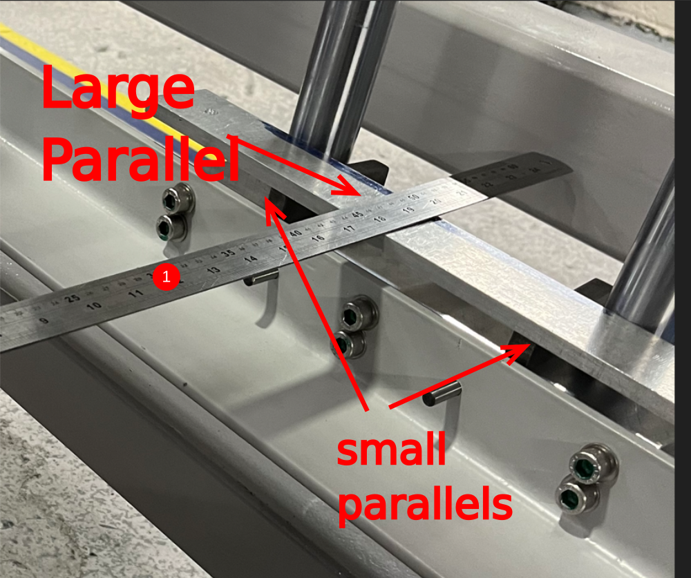
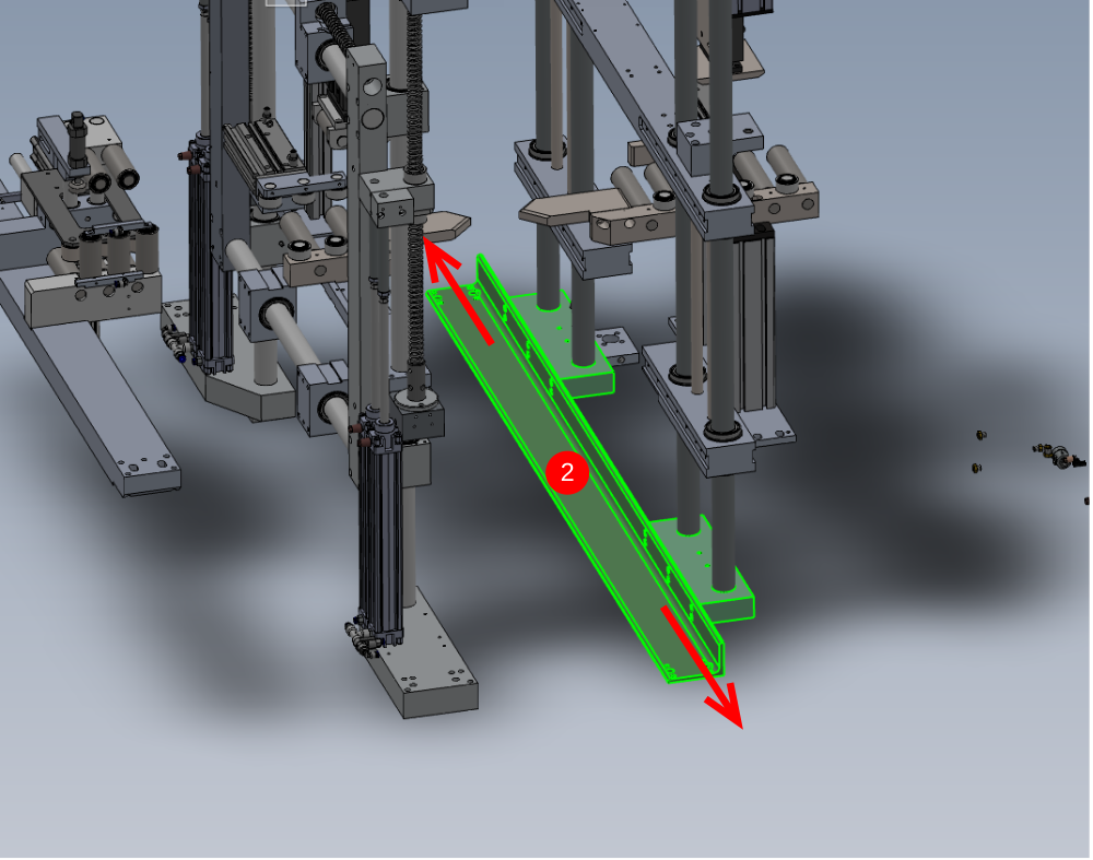
Étape 4 - Adjust bottom mount
Using step 3 calculation, set lower position to measurement obtained
1 Position 2 off small parallels and 1 off large parallel as shown
2 Take indicated measurement
3 Move lower beam mount to achieve correct measurement
4 Ensure 4 off M10 flat bottomed grub screws are touching main frame and hold position with G clamp and support blocks
Repeat for opposite side , double check all measurements when adjustment is carried out , until both measurements are exactly set to calculated measurement (tolerance +- 0.25mm )
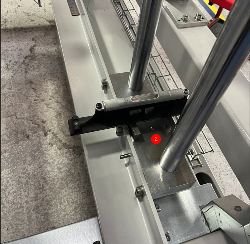
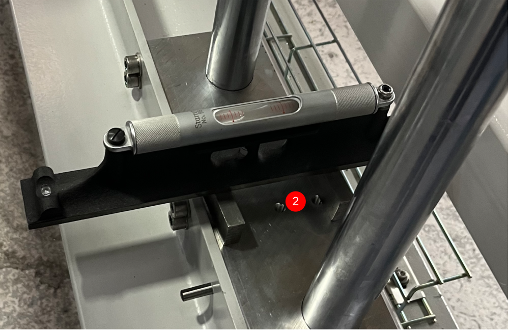
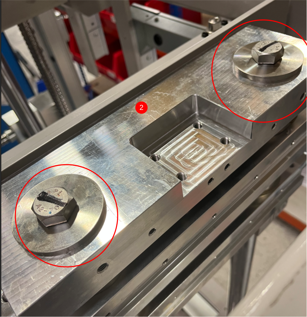
Étape 5 - Level Lower mount
1 Level lower mount Y Axis as shown, using 1 meter straight edge and engineers level. Adjust using lower side M10 grubscrews
2 Level x axis of indicated blocks as shown. Use 2 small parallels and engineers level . Use M10 Grubscrews and M16 bolt beneath to adjust level
Repeat for both sides
Étape 6 - Finalise Fasteners
Finalise the following fasteners
1 Ensure 8 off grubscrews that hold vertical shaft position are swapped for M8 x 16 kcp grubscrews , glued and tightened
2 Ensure 8 off M16 bolts are glued and tightened
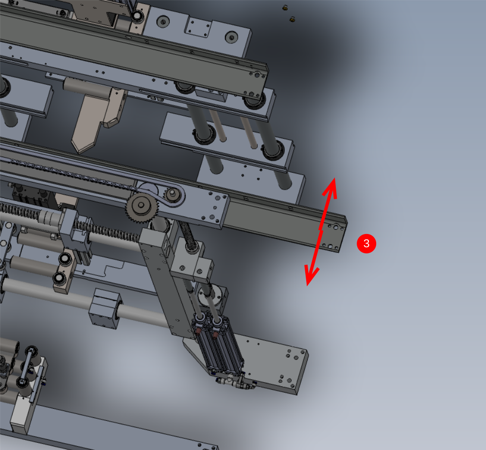
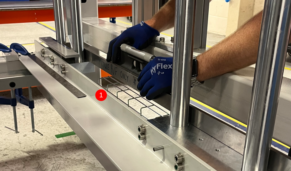
Étape 7 - Adjust Vertical
Use shaft setting block to check level of vertical shafts
1 Attach setting block to 1 off outside shaft as shown
2 Adjust lower beam molunt in direction shown to set level
3 Move setting block to other outer shaft and recheck level. Any discrepancy should be equalised between shafts
Étape 8 - Double Check
Double check all previous levelling and measurements to confirm all criteria has been met

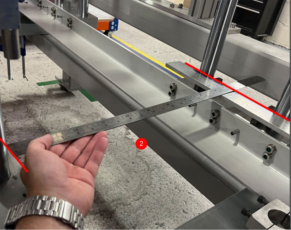
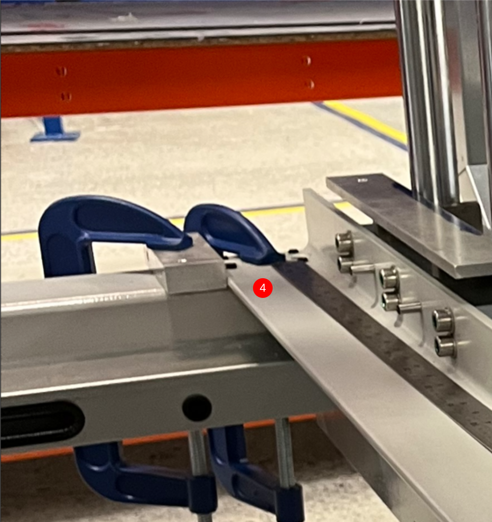
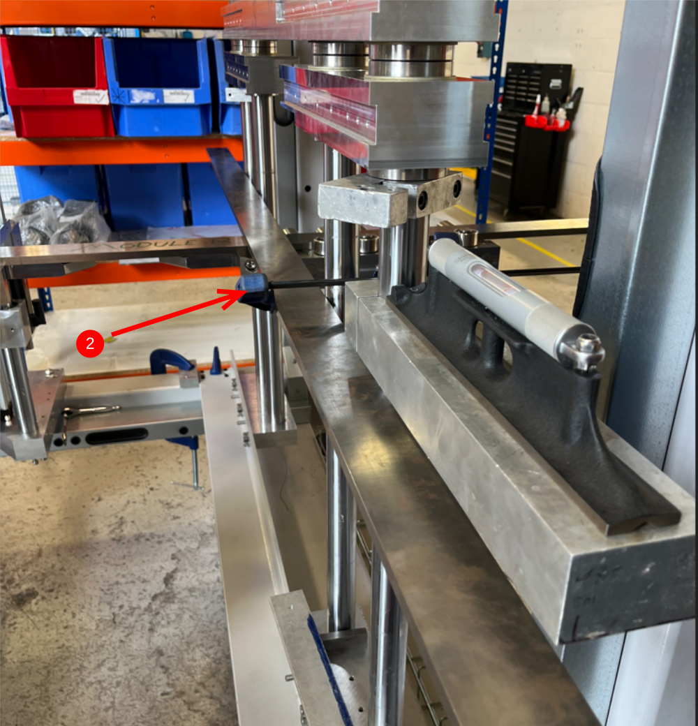
Étape 9 - Squareness Check
V notch sub frame must be square clamps.
To check this
1 Use 2 meter straight edge against datum rollers as shown
2 Use 2 meter straight edge to align over front face of 4 vertical subframe shafts. Hold in position with 2 quick clamps
3 Use engineers square to check squareness. If this check shows any discrepancy, Recheck all previous settings to identify fault area
Étape 10 - Sign off
Quality check required at this stage from supervisor
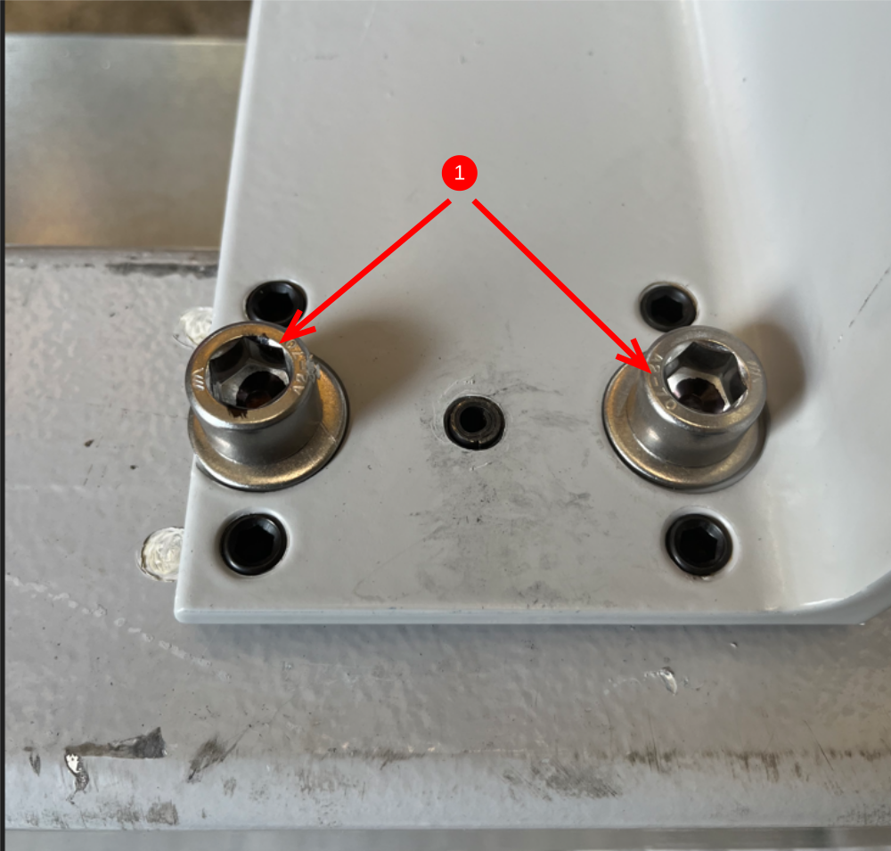
Étape 11 - Final fixings
1 Drill and Tap M12 and fit 2 off M12 x 25 socket caps per side ( 4 off in total ) in lower beam mount
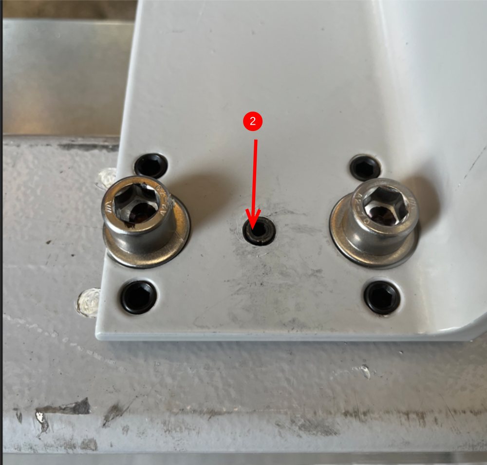
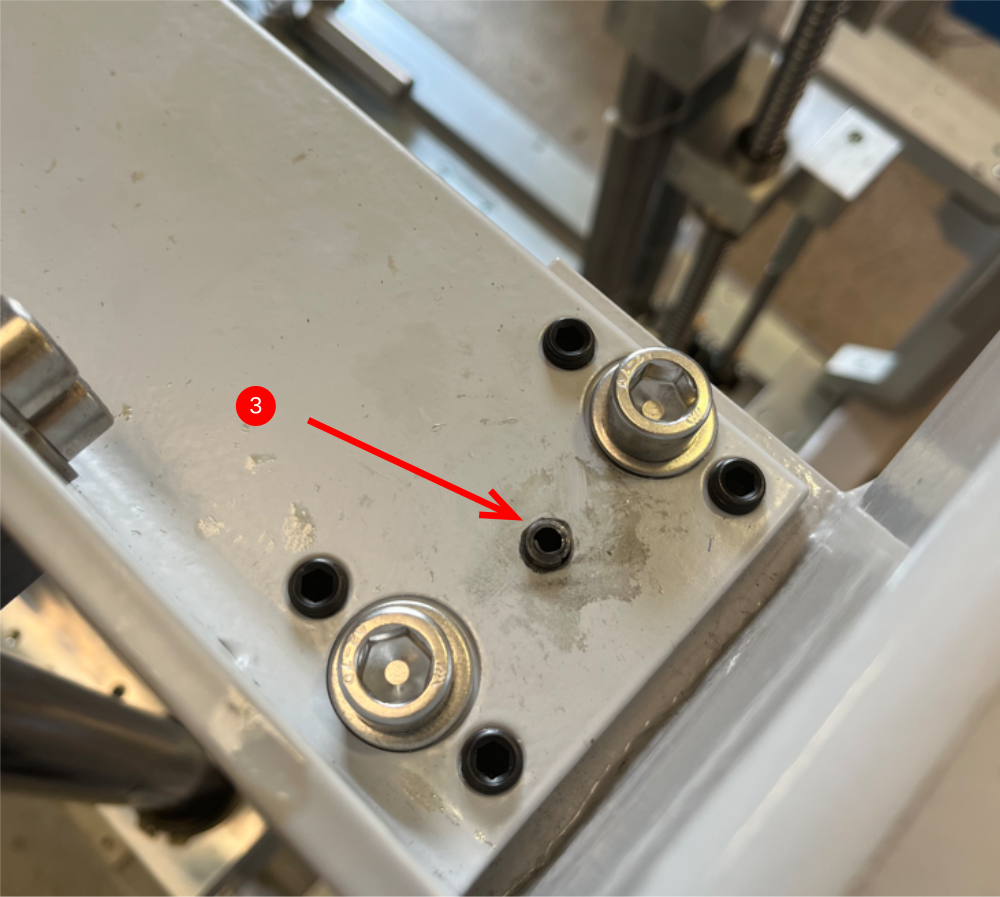
2 Drill 8mm hole and add 8mm spiral pin as shown ( 1 per side ) in lower beam mount
3 Drill 8mm hole and add 8mm spiral pin as shown ( 1 per side ) in upper beam mount
Étape 12 - Add Thread lock
Add Loctite 290 to all adjustment grubscrews used
16 off m10 x 12
Add Loctite 243 to M12 socket caps 8 off

Draft
 Français
 English
 Deutsch
 Español
 Italiano
 Português