| [version en cours de rédaction] | [version en cours de rédaction] |
| Ligne 209 : | Ligne 209 : | ||
|Step_Picture_00=R0015311_Install_and_Align_Datum_rollers_Screenshot_2023-09-21_134759.png | |Step_Picture_00=R0015311_Install_and_Align_Datum_rollers_Screenshot_2023-09-21_134759.png | ||
|Step_Picture_01=R0015311_Install_and_Align_Datum_rollers_Screenshot_2023-09-21_134815.png | |Step_Picture_01=R0015311_Install_and_Align_Datum_rollers_Screenshot_2023-09-21_134815.png | ||
| + | }} | ||
| + | {{Tuto Step | ||
| + | |Step_Title=<translate>Cut tables</translate> | ||
| + | |Step_Content=<translate>Cut tables must be fitted during this alignment. This will ensure cut tables are accurately set and and any dicrepancies will be identified at this stage . | ||
| + | |||
| + | |||
| + | Please ensure all tolerances of maximum 0.002"/0.05 mm is adhered to all times on set up</translate> | ||
| + | |Step_Picture_00=R0015338_Bench_Assemble_Serial_Plate_caution.png | ||
}} | }} | ||
{{Tuto Step | {{Tuto Step | ||
Version actuelle datée du 28 mars 2024 à 17:23
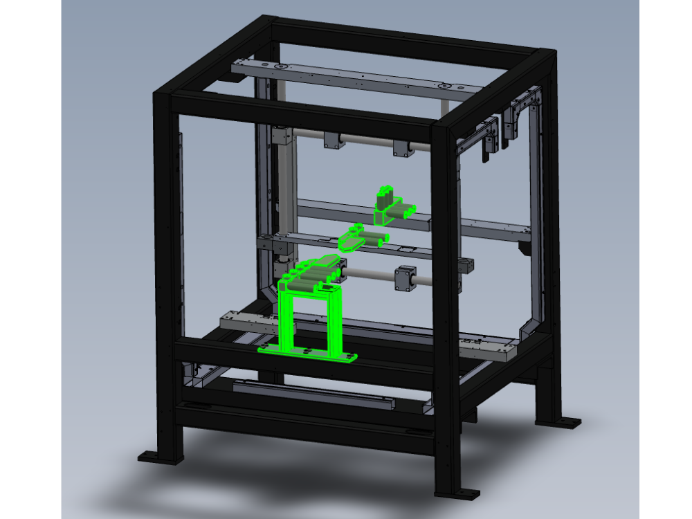
Fitting and alignment details

Difficulté
Difficile
Durée
4 heure(s)
Sommaire
- 1 Introduction
- 2 Étape 1 - Unless otherwise stated
- 3 Étape 2 - Level Infeed datum rollers
- 4 Étape 3 - Level V notch datum rollers
- 5 Étape 4 - Level between rollers
- 6 Étape 5 - Check alignment and levels
- 7 Étape 6 - Adjust Roller C
- 8 Étape 7 - Subframe adjustment
- 9 Étape 8 - Backfence roller alignment
- 10 Étape 9 - Squareness Check
- 11 Étape 10 - Adjusting squareness
- 12 Étape 11 - Confirm squareness
- 13 Étape 12 - Cut tables
- 14 Étape 13 - Recheck levels and alignment
- 15 Étape 14 - Align datum B rollers
- 16 Étape 15 - Recheck squareness
- 17 Étape 16 - Finalise Datum C
- 18 Étape 17 - Quality check
- 19 Étape 18 - Dowel front bar
- 20 Étape 19 - Refit Datum A roller and blower
- 21 Commentaires
Introduction
Tools required
Standard hex key set
2 meter straight edge
1 meter straight edge
12" engineers level
12" inch engineers square
Feeler gauge set
Parts Required
Étape 1 - Unless otherwise stated
Use locktite 243 on all fasteners
Use loctite 572 on all threaded pneumatic connection
Pen mark all fasteners to show finalised

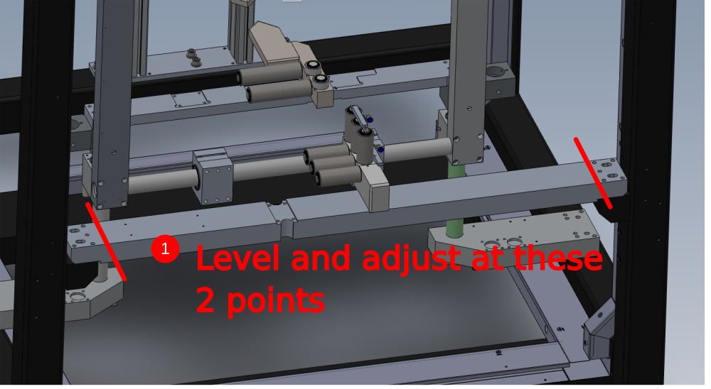
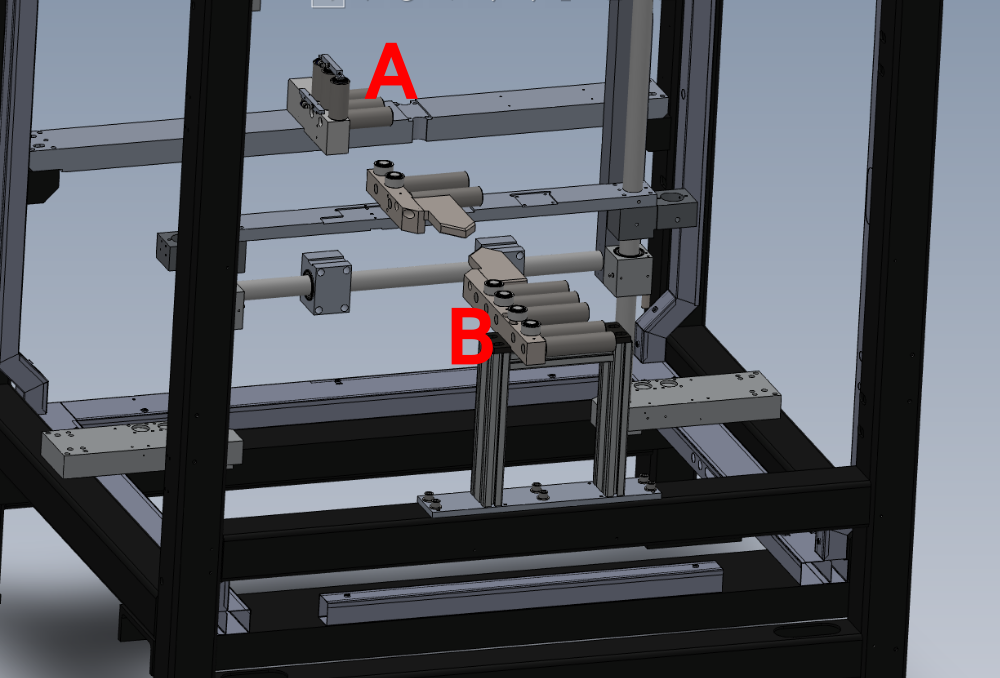
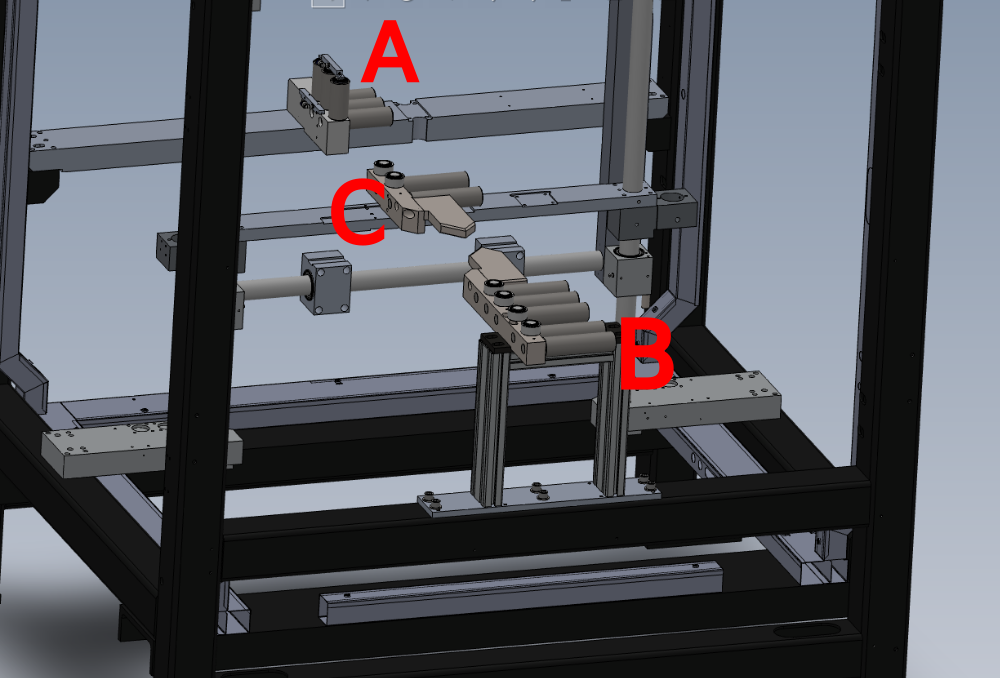
Étape 2 - Level Infeed datum rollers
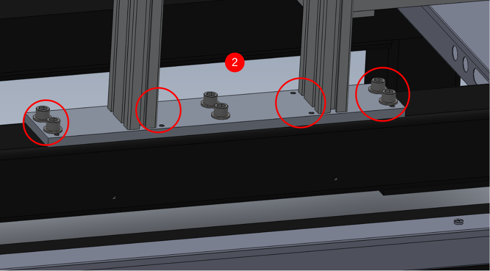
1 Level On X axis using engineers level and adjusting grubscrews in indicated areas
2 Level from Rollers at indicated point. Adjust previous level points evenly to adjust level reading on rollers
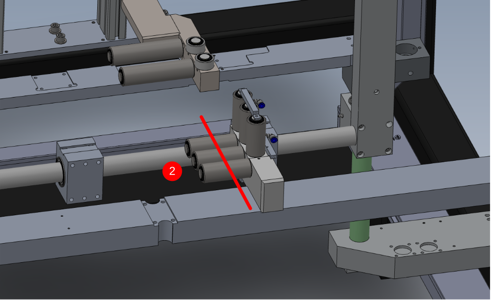
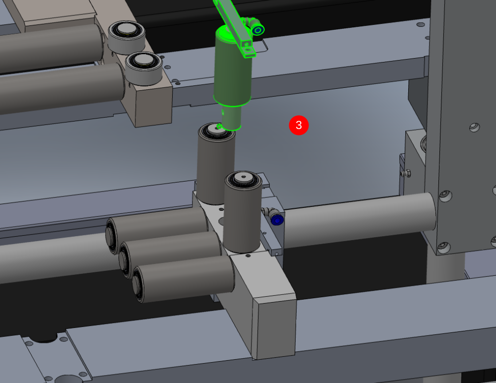
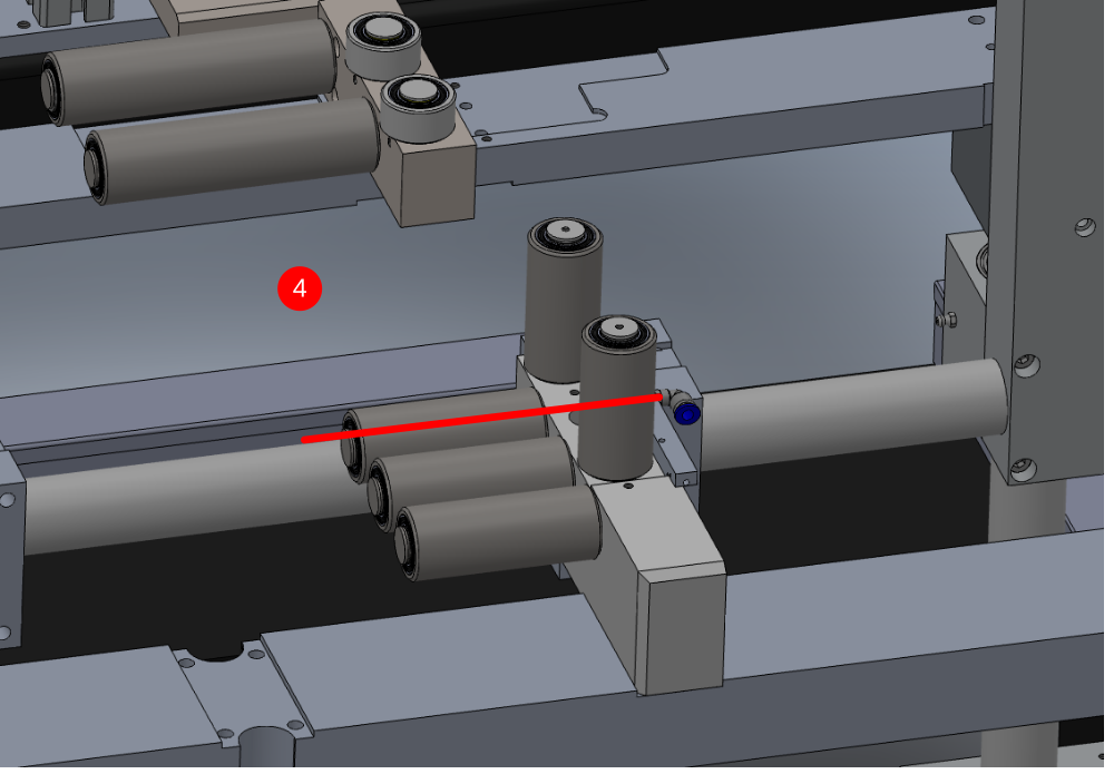
3 Remove Middle roller and top blower
4 Use 300mm parallels to span rollers and engineers level to check and adjust Y axis level of rollers
Étape 3 - Level V notch datum rollers
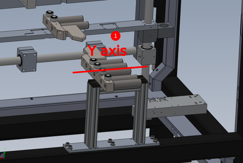
1 Level Y axis with engineers level and 300mm parallels.
2 Adjust using M8 flat bottom jacking grubscrews
3 Check and adjust X axis level
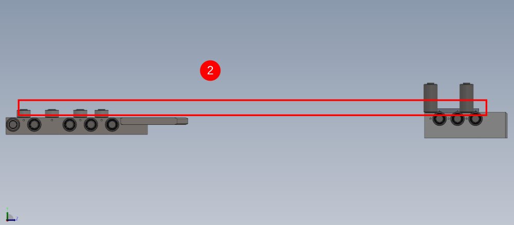
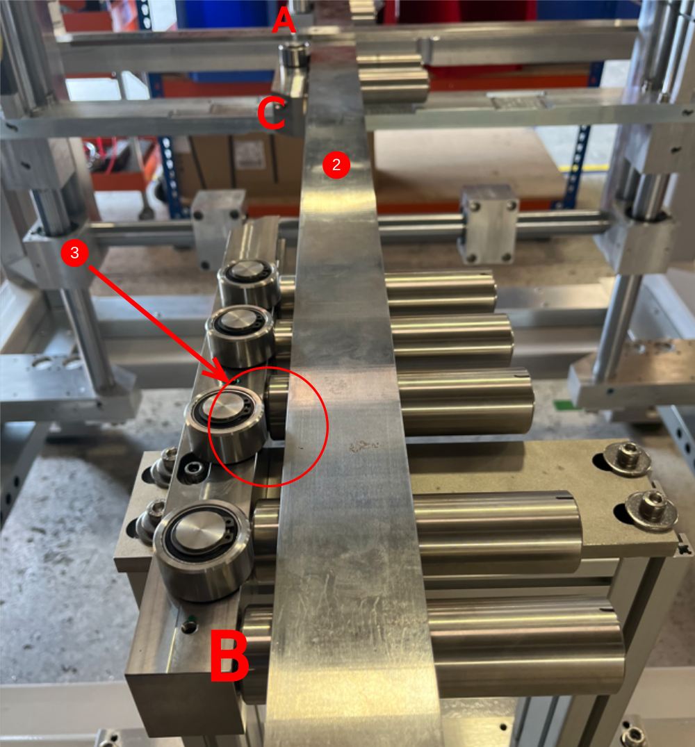
Étape 4 - Level between rollers
1 Use a 2 meter straight edge to span between rollers A and B
2 Use engineers level on straight edge to identify if either A or B is the low point
3 Raise A or B to bring level


Étape 5 - Check alignment and levels
1 Check all levels again after adjusting rollers A and B
2 Use 2 meter straight edge and feeler gauges to check alignment of rollers and cut table
Adhere to tolerance of - 0.002"

Étape 6 - Adjust Roller C
Span from roller A to B with 2 meter straight edge
Identify if roller C is high or low
If high, increase height of rollers A and B and re set levels
If low, follow next step for subframe adjustment

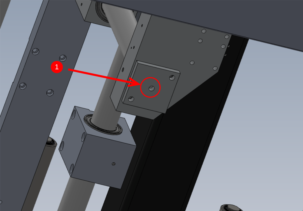
Étape 7 - Subframe adjustment
This step is required is centre rollers C require lifting
1 Release lock nut on plate 2 off
2 Release M8 grubscrew 2 off
3 Release M12 socket caps 4 off
4 Adjust in equal turns M10 jacking grubscrews
Re level and tighten subframe
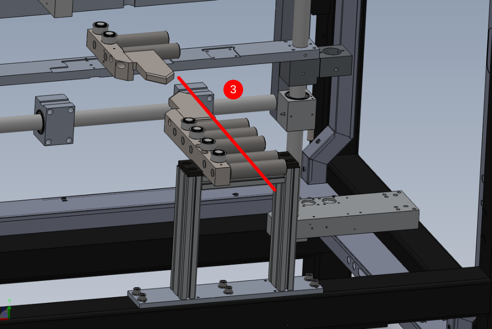
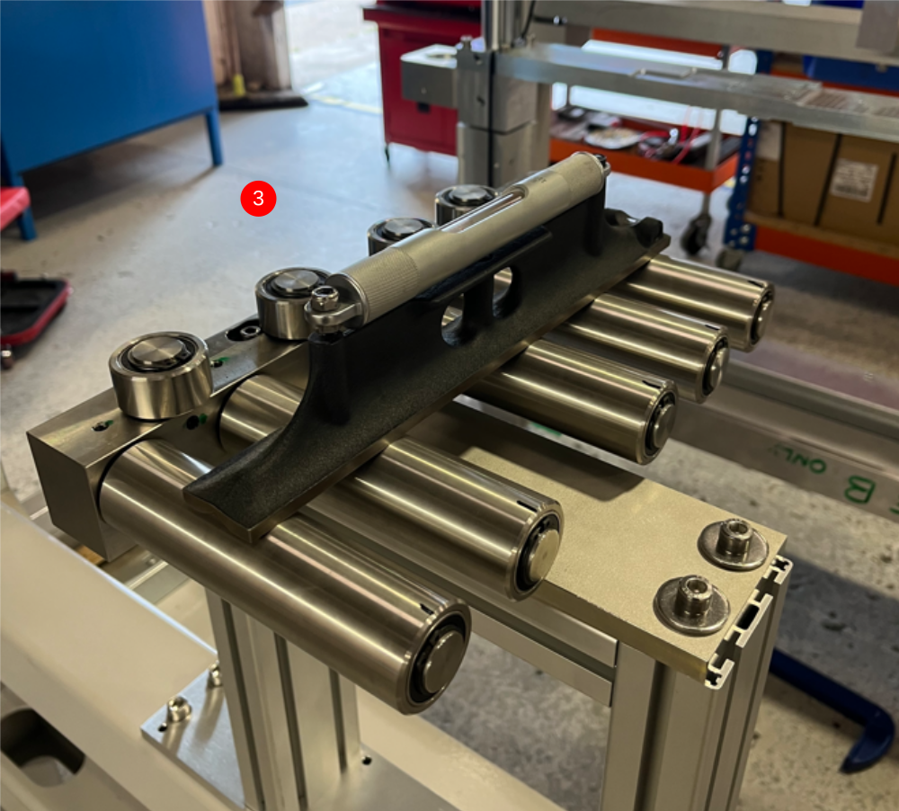
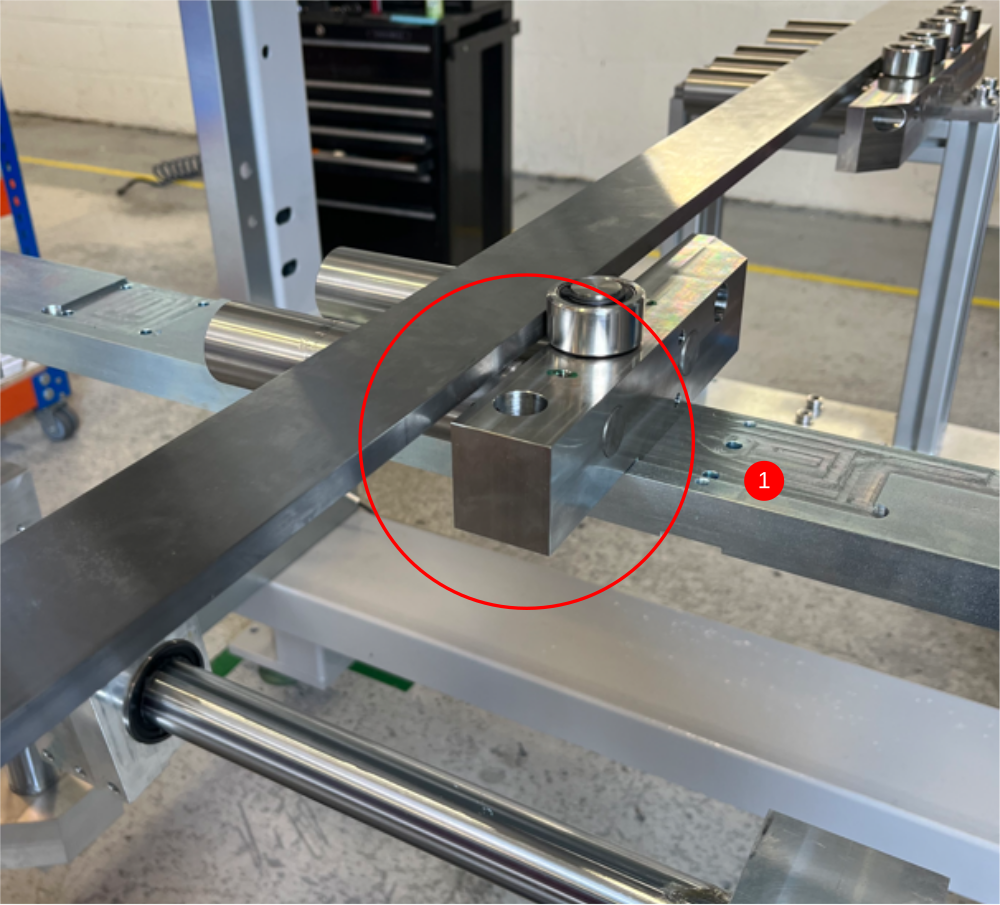
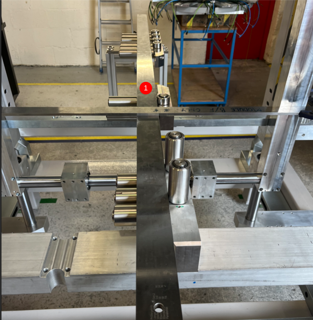
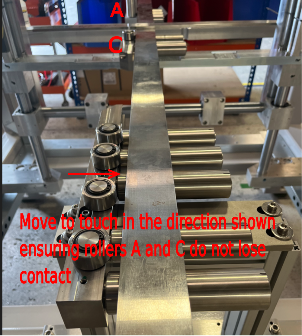
Étape 8 - Backfence roller alignment
1 Remove roller from clamp C as shown
2 Use 2 meter straight edge as shown, pushed against roller A and C
3 Ensure Rollers B are moved away from straight edge
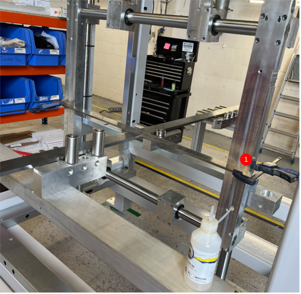
Étape 9 - Squareness Check
1 Use 1 meter straight edge as shown, and hold in position against z axis support blocks
2 Check as shown with engineers square to asses squareness of sub frame to clamps
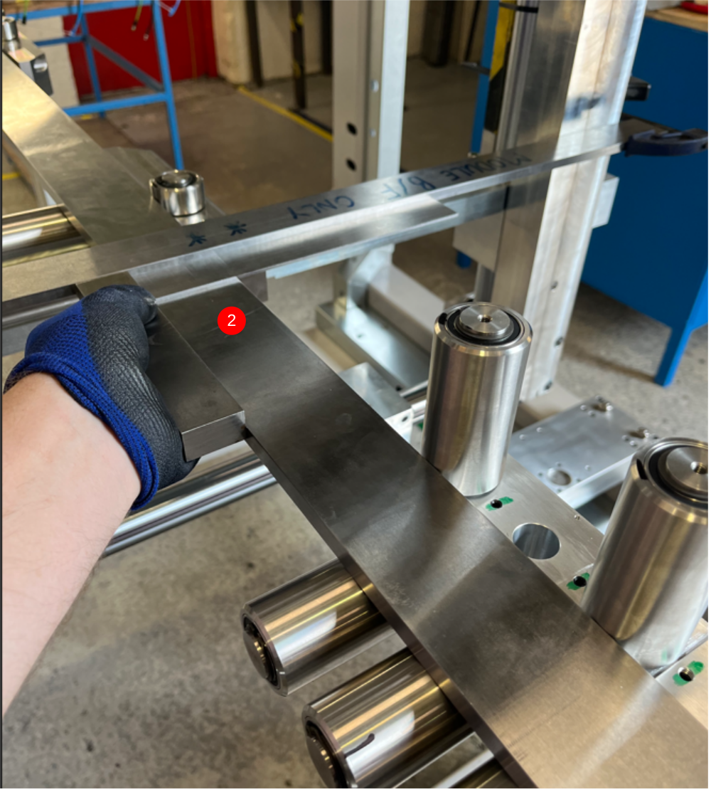
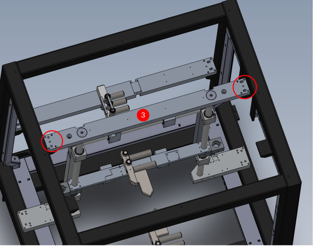
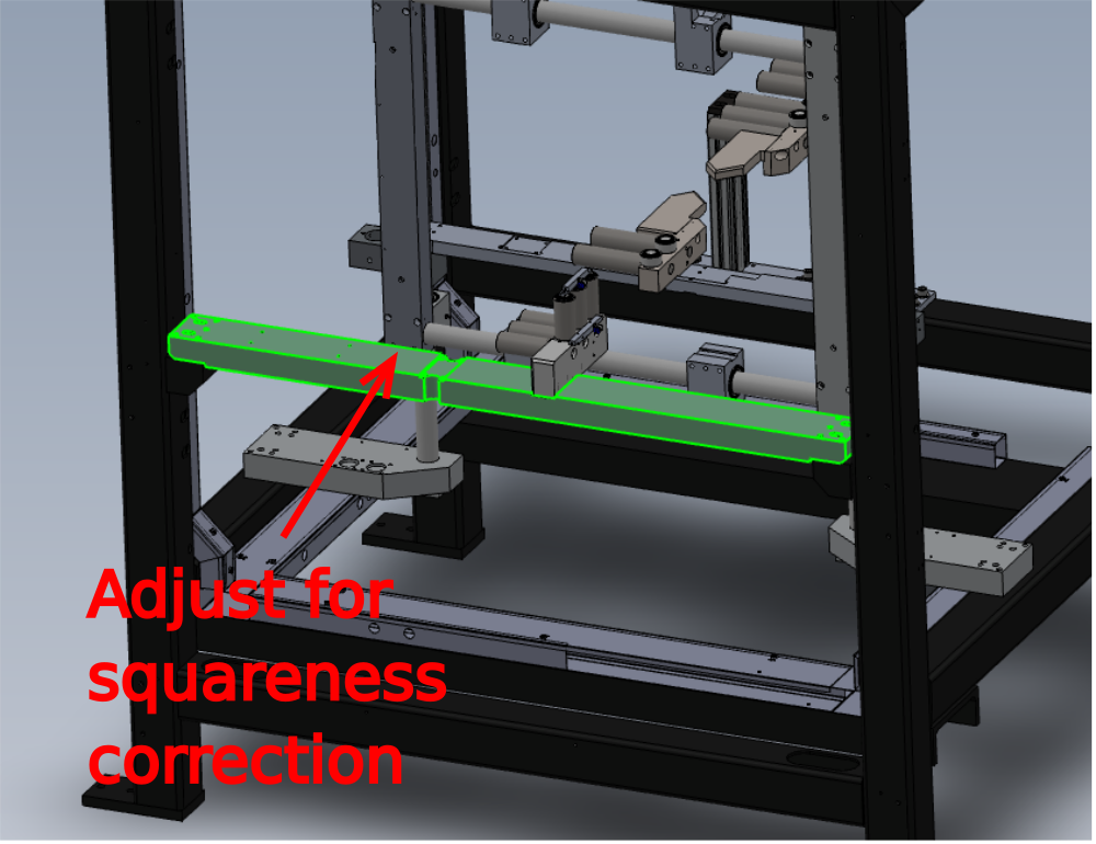
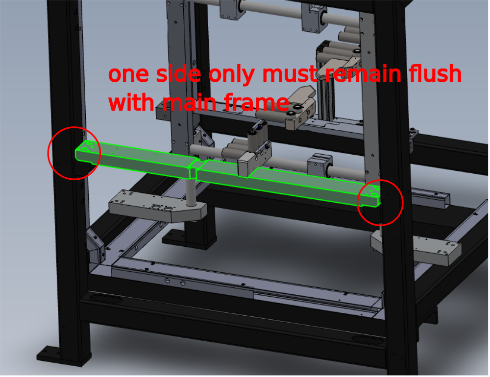
Étape 10 - Adjusting squareness
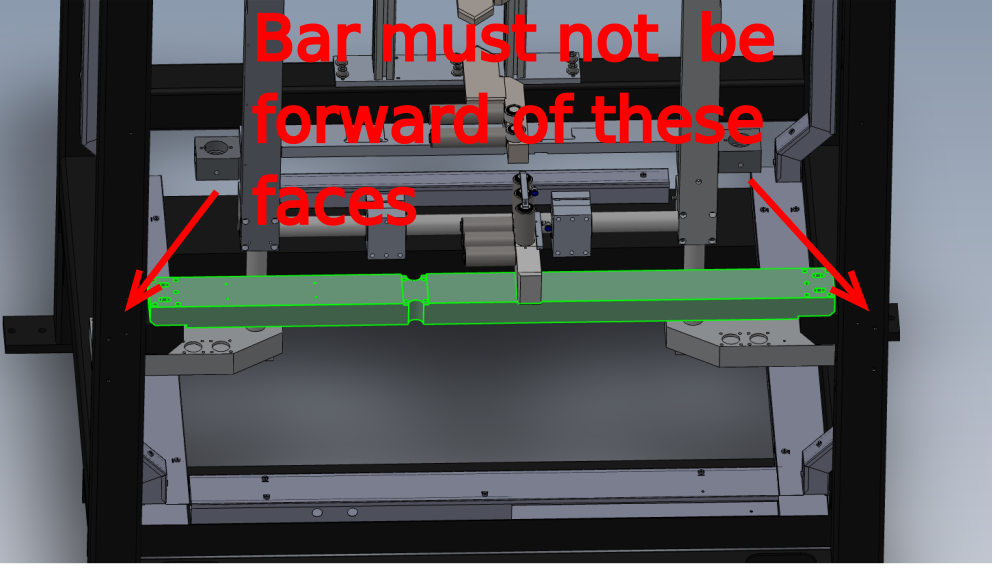
To adjust squareness, indicated bar must be adjusted
Always ensure when adjusting that the following is observed
- Indicated bar must not protrude Exterior face of main frame
- One side of bar must always remain flush with main frame
Étape 11 - Confirm squareness
Squareness of datum faces to sub frame must be set with no tolerance.
Perfect squareness should be achieved


Étape 12 - Cut tables
Cut tables must be fitted during this alignment. This will ensure cut tables are accurately set and and any dicrepancies will be identified at this stage .
Please ensure all tolerances of maximum 0.002"/0.05 mm is adhered to all times on set up

Étape 13 - Recheck levels and alignment
Recheck all levels and alignment of rollers in all aspects once squareness setting has been performed. These settings are possible to change after front bar has been adjusted
Étape 14 - Align datum B rollers
Datum rollers B can now be aligned using A and C as the Datum
With the 2 meter straight edge against A and C, adjust B to alignment is achieved on back fences
Check with 0.002" feeler gauge on all rollers when setting
Étape 15 - Recheck squareness
Squareness must be rechecked once Datum rollers B have been aligned , using the same check as step 9
Étape 16 - Finalise Datum C
Datum C now requires roller refitting and repositioning
1 Refit roller
2 Slacken 2 off M6 fasteners that hold Roller assembly C in place
3 Ensure straight edge is firmly against roller assemblies A and B
4 Position and Tighten Roller assembly C to align with 2 meter straight edge
5 Check with 0.002" feeler gauge that all rollers are aligned and in tolerance

Étape 17 - Quality check
Ensure once set, all levels and alignment covered in this procedure, as double checked and confirmed as correct
Supervisor sign off required

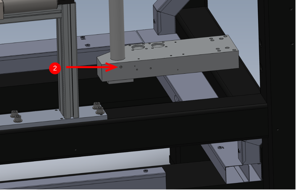
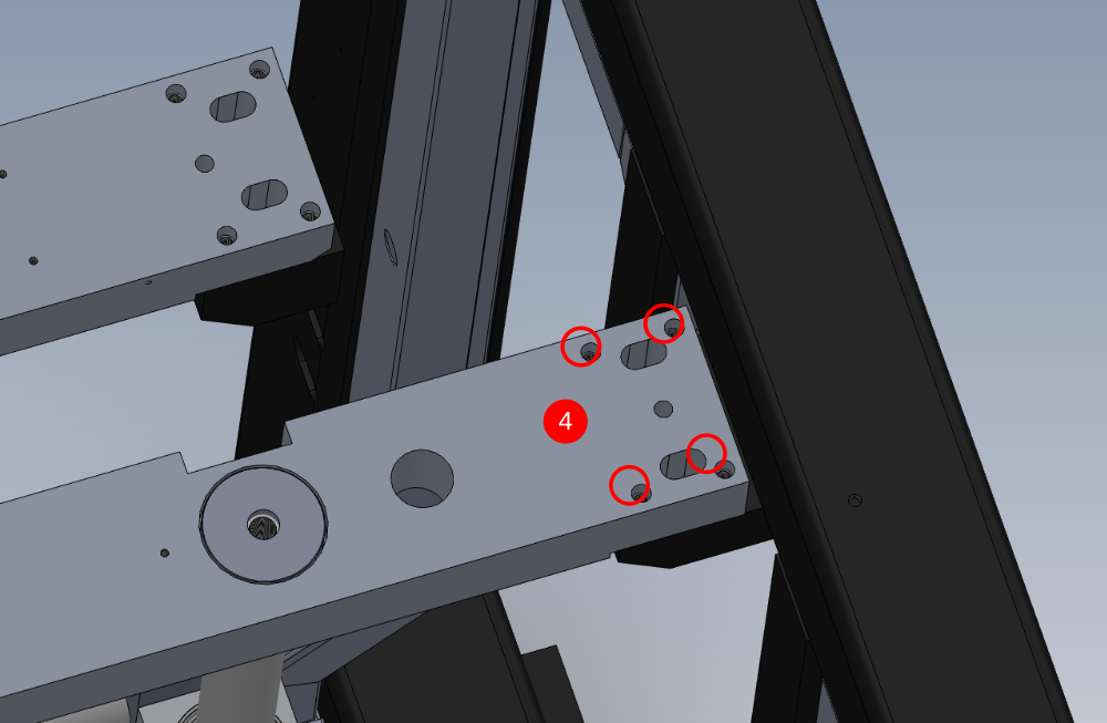
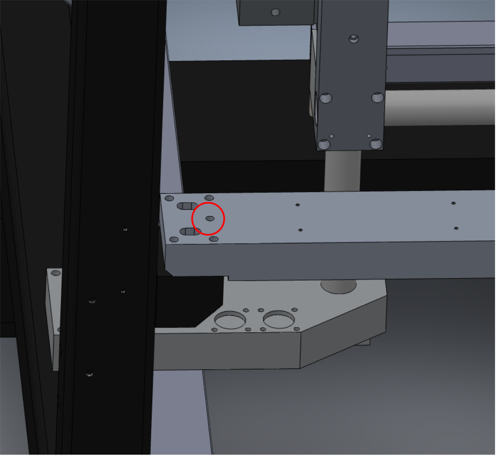
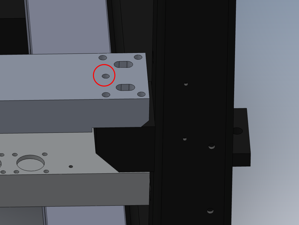
Étape 18 - Dowel front bar
Front Bar indicated requires doweling in position
1 Drill 9.5mm to a depth of 25mm into steel support tab at the 2 indicated points
2 Open holes to 10mm diameter
3 Insert 2 off 10mm x 60mm spiral pins to fix position . Ensure dowel is sitting equally between clamp bar and steel support
Étape 19 - Refit Datum A roller and blower
Once dowelling and sign off is complete, remove roller and blower from datum A should be refitted and fasteners finalised .

Draft
 Français
 English
 Deutsch
 Español
 Italiano
 Português