| [version en cours de rédaction] | [version en cours de rédaction] |
| Ligne 361 : | Ligne 361 : | ||
|Step_Picture_03=Install_Wiring_loom_for_Rotary_loom_Screenshot_2023-05-31_120036.png | |Step_Picture_03=Install_Wiring_loom_for_Rotary_loom_Screenshot_2023-05-31_120036.png | ||
|Step_Picture_03_annotation={"version":"2.4.6","objects":[{"type":"image","version":"2.4.6","originX":"left","originY":"top","left":0,"top":0,"width":650,"height":695,"fill":"rgb(0,0,0)","stroke":null,"strokeWidth":0,"strokeDashArray":null,"strokeLineCap":"butt","strokeDashOffset":0,"strokeLineJoin":"miter","strokeMiterLimit":4,"scaleX":0.92,"scaleY":0.92,"angle":0,"flipX":false,"flipY":false,"opacity":1,"shadow":null,"visible":true,"clipTo":null,"backgroundColor":"","fillRule":"nonzero","paintFirst":"fill","globalCompositeOperation":"source-over","transformMatrix":null,"skewX":0,"skewY":0,"crossOrigin":"","cropX":0,"cropY":0,"src":"https://stuga.dokit.app/images/3/3d/Install_Wiring_loom_for_Rotary_loom_Screenshot_2023-05-31_120036.png","filters":[]},{"type":"wfnumberedbullet","version":"2.4.6","originX":"left","originY":"top","left":413,"top":393,"width":25,"height":25,"fill":"rgb(0,0,0)","stroke":"#FF0000","strokeWidth":0,"strokeDashArray":null,"strokeLineCap":"butt","strokeDashOffset":0,"strokeLineJoin":"miter","strokeMiterLimit":4,"scaleX":1,"scaleY":1,"angle":0,"flipX":false,"flipY":false,"opacity":1,"shadow":null,"visible":true,"clipTo":null,"backgroundColor":"","fillRule":"nonzero","paintFirst":"fill","globalCompositeOperation":"source-over","transformMatrix":null,"skewX":0,"skewY":0,"objects":[{"type":"circle","version":"2.4.6","originX":"center","originY":"center","left":0,"top":0,"width":24,"height":24,"fill":"#FF0000","stroke":null,"strokeWidth":1,"strokeDashArray":null,"strokeLineCap":"butt","strokeDashOffset":0,"strokeLineJoin":"miter","strokeMiterLimit":4,"scaleX":1,"scaleY":1,"angle":0,"flipX":false,"flipY":false,"opacity":1,"shadow":null,"visible":true,"clipTo":null,"backgroundColor":"","fillRule":"nonzero","paintFirst":"fill","globalCompositeOperation":"source-over","transformMatrix":null,"skewX":0,"skewY":0,"radius":12,"startAngle":0,"endAngle":6.283185307179586},{"type":"text","version":"2.4.6","originX":"center","originY":"center","left":0,"top":0,"width":7.79,"height":15.82,"fill":"rgba(255,255,255,255)","stroke":null,"strokeWidth":1,"strokeDashArray":null,"strokeLineCap":"butt","strokeDashOffset":0,"strokeLineJoin":"miter","strokeMiterLimit":4,"scaleX":1,"scaleY":1,"angle":0,"flipX":false,"flipY":false,"opacity":1,"shadow":null,"visible":true,"clipTo":null,"backgroundColor":"","fillRule":"nonzero","paintFirst":"fill","globalCompositeOperation":"source-over","transformMatrix":null,"skewX":0,"skewY":0,"text":"4","fontSize":14,"fontWeight":"normal","fontFamily":"arial","fontStyle":"normal","lineHeight":1.16,"underline":false,"overline":false,"linethrough":false,"textAlign":"left","textBackgroundColor":"","charSpacing":0,"styles":{} }],"number":4}],"height":642,"width":600} | |Step_Picture_03_annotation={"version":"2.4.6","objects":[{"type":"image","version":"2.4.6","originX":"left","originY":"top","left":0,"top":0,"width":650,"height":695,"fill":"rgb(0,0,0)","stroke":null,"strokeWidth":0,"strokeDashArray":null,"strokeLineCap":"butt","strokeDashOffset":0,"strokeLineJoin":"miter","strokeMiterLimit":4,"scaleX":0.92,"scaleY":0.92,"angle":0,"flipX":false,"flipY":false,"opacity":1,"shadow":null,"visible":true,"clipTo":null,"backgroundColor":"","fillRule":"nonzero","paintFirst":"fill","globalCompositeOperation":"source-over","transformMatrix":null,"skewX":0,"skewY":0,"crossOrigin":"","cropX":0,"cropY":0,"src":"https://stuga.dokit.app/images/3/3d/Install_Wiring_loom_for_Rotary_loom_Screenshot_2023-05-31_120036.png","filters":[]},{"type":"wfnumberedbullet","version":"2.4.6","originX":"left","originY":"top","left":413,"top":393,"width":25,"height":25,"fill":"rgb(0,0,0)","stroke":"#FF0000","strokeWidth":0,"strokeDashArray":null,"strokeLineCap":"butt","strokeDashOffset":0,"strokeLineJoin":"miter","strokeMiterLimit":4,"scaleX":1,"scaleY":1,"angle":0,"flipX":false,"flipY":false,"opacity":1,"shadow":null,"visible":true,"clipTo":null,"backgroundColor":"","fillRule":"nonzero","paintFirst":"fill","globalCompositeOperation":"source-over","transformMatrix":null,"skewX":0,"skewY":0,"objects":[{"type":"circle","version":"2.4.6","originX":"center","originY":"center","left":0,"top":0,"width":24,"height":24,"fill":"#FF0000","stroke":null,"strokeWidth":1,"strokeDashArray":null,"strokeLineCap":"butt","strokeDashOffset":0,"strokeLineJoin":"miter","strokeMiterLimit":4,"scaleX":1,"scaleY":1,"angle":0,"flipX":false,"flipY":false,"opacity":1,"shadow":null,"visible":true,"clipTo":null,"backgroundColor":"","fillRule":"nonzero","paintFirst":"fill","globalCompositeOperation":"source-over","transformMatrix":null,"skewX":0,"skewY":0,"radius":12,"startAngle":0,"endAngle":6.283185307179586},{"type":"text","version":"2.4.6","originX":"center","originY":"center","left":0,"top":0,"width":7.79,"height":15.82,"fill":"rgba(255,255,255,255)","stroke":null,"strokeWidth":1,"strokeDashArray":null,"strokeLineCap":"butt","strokeDashOffset":0,"strokeLineJoin":"miter","strokeMiterLimit":4,"scaleX":1,"scaleY":1,"angle":0,"flipX":false,"flipY":false,"opacity":1,"shadow":null,"visible":true,"clipTo":null,"backgroundColor":"","fillRule":"nonzero","paintFirst":"fill","globalCompositeOperation":"source-over","transformMatrix":null,"skewX":0,"skewY":0,"text":"4","fontSize":14,"fontWeight":"normal","fontFamily":"arial","fontStyle":"normal","lineHeight":1.16,"underline":false,"overline":false,"linethrough":false,"textAlign":"left","textBackgroundColor":"","charSpacing":0,"styles":{} }],"number":4}],"height":642,"width":600} | ||
| + | }} | ||
| + | {{Tuto Step | ||
| + | |Step_Title=<translate>Finalize dowel holes</translate> | ||
| + | |Step_Content=<translate>Once spindles are final fixed, preventative prep must be added to dowel holes to stop slip of dowel from hole. | ||
| + | |||
| + | |||
| + | |||
| + | Add 1 off centre dot to each dowel position to slightly swage over top of hole</translate> | ||
| + | |Step_Picture_00=R0015305_Install_Wiring_loom_for_Rotary_loom_Screenshot_2024-02-27_125522.png | ||
| + | |Step_Picture_00_annotation={"version":"2.4.6","objects":[{"type":"image","version":"2.4.6","originX":"left","originY":"top","left":0,"top":0,"width":440,"height":472,"fill":"rgb(0,0,0)","stroke":null,"strokeWidth":0,"strokeDashArray":null,"strokeLineCap":"butt","strokeDashOffset":0,"strokeLineJoin":"miter","strokeMiterLimit":4,"scaleX":1.36,"scaleY":1.36,"angle":0,"flipX":false,"flipY":false,"opacity":1,"shadow":null,"visible":true,"clipTo":null,"backgroundColor":"","fillRule":"nonzero","paintFirst":"fill","globalCompositeOperation":"source-over","transformMatrix":null,"skewX":0,"skewY":0,"crossOrigin":"","cropX":0,"cropY":0,"src":"https://stuga.dokit.app/images/e/e0/R0015305_Install_Wiring_loom_for_Rotary_loom_Screenshot_2024-02-27_125522.png","filters":[]},{"type":"wfellipse","version":"2.4.6","originX":"center","originY":"center","left":358.67,"top":294.33,"width":122.3,"height":122.3,"fill":"rgba(255,0,0,0)","stroke":"#FF0000","strokeWidth":2,"strokeDashArray":null,"strokeLineCap":"butt","strokeDashOffset":0,"strokeLineJoin":"miter","strokeMiterLimit":4,"scaleX":1,"scaleY":1,"angle":0,"flipX":false,"flipY":false,"opacity":1,"shadow":null,"visible":true,"clipTo":null,"backgroundColor":"","fillRule":"nonzero","paintFirst":"fill","globalCompositeOperation":"source-over","transformMatrix":null,"skewX":0,"skewY":0,"rx":61.14939979340817,"ry":61.14939979340817}],"height":644,"width":600} | ||
| + | |Step_Picture_01=R0015305_Install_Wiring_loom_for_Rotary_loom_Screenshot_2024-02-27_125530.png | ||
| + | |Step_Picture_01_annotation={"version":"2.4.6","objects":[{"type":"image","version":"2.4.6","originX":"left","originY":"top","left":0,"top":0,"width":505,"height":478,"fill":"rgb(0,0,0)","stroke":null,"strokeWidth":0,"strokeDashArray":null,"strokeLineCap":"butt","strokeDashOffset":0,"strokeLineJoin":"miter","strokeMiterLimit":4,"scaleX":1.19,"scaleY":1.19,"angle":0,"flipX":false,"flipY":false,"opacity":1,"shadow":null,"visible":true,"clipTo":null,"backgroundColor":"","fillRule":"nonzero","paintFirst":"fill","globalCompositeOperation":"source-over","transformMatrix":null,"skewX":0,"skewY":0,"crossOrigin":"","cropX":0,"cropY":0,"src":"https://stuga.dokit.app/images/c/ce/R0015305_Install_Wiring_loom_for_Rotary_loom_Screenshot_2024-02-27_125530.png","filters":[]},{"type":"wfellipse","version":"2.4.6","originX":"center","originY":"center","left":103.39,"top":121.61,"width":78.6,"height":78.6,"fill":"rgba(255,0,0,0)","stroke":"#FF0000","strokeWidth":2,"strokeDashArray":null,"strokeLineCap":"butt","strokeDashOffset":0,"strokeLineJoin":"miter","strokeMiterLimit":4,"scaleX":1,"scaleY":1,"angle":0,"flipX":false,"flipY":false,"opacity":1,"shadow":null,"visible":true,"clipTo":null,"backgroundColor":"","fillRule":"nonzero","paintFirst":"fill","globalCompositeOperation":"source-over","transformMatrix":null,"skewX":0,"skewY":0,"rx":39.30064750797575,"ry":39.30064750797575},{"type":"wfellipse","version":"2.4.6","originX":"center","originY":"center","left":102.1,"top":311.9,"width":72.1,"height":72.1,"fill":"rgba(255,0,0,0)","stroke":"#FF0000","strokeWidth":2,"strokeDashArray":null,"strokeLineCap":"butt","strokeDashOffset":0,"strokeLineJoin":"miter","strokeMiterLimit":4,"scaleX":1,"scaleY":1,"angle":0,"flipX":false,"flipY":false,"opacity":1,"shadow":null,"visible":true,"clipTo":null,"backgroundColor":"","fillRule":"nonzero","paintFirst":"fill","globalCompositeOperation":"source-over","transformMatrix":null,"skewX":0,"skewY":0,"rx":36.047779437051354,"ry":36.047779437051354},{"type":"wfellipse","version":"2.4.6","originX":"center","originY":"center","left":477.61,"top":111.39,"width":77.11,"height":77.11,"fill":"rgba(255,0,0,0)","stroke":"#FF0000","strokeWidth":2,"strokeDashArray":null,"strokeLineCap":"butt","strokeDashOffset":0,"strokeLineJoin":"miter","strokeMiterLimit":4,"scaleX":1,"scaleY":1,"angle":0,"flipX":false,"flipY":false,"opacity":1,"shadow":null,"visible":true,"clipTo":null,"backgroundColor":"","fillRule":"nonzero","paintFirst":"fill","globalCompositeOperation":"source-over","transformMatrix":null,"skewX":0,"skewY":0,"rx":38.55566438872905,"ry":38.55566438872905},{"type":"wfellipse","version":"2.4.6","originX":"center","originY":"center","left":489.29,"top":302.71,"width":64.79,"height":64.79,"fill":"rgba(255,0,0,0)","stroke":"#FF0000","strokeWidth":2,"strokeDashArray":null,"strokeLineCap":"butt","strokeDashOffset":0,"strokeLineJoin":"miter","strokeMiterLimit":4,"scaleX":1,"scaleY":1,"angle":0,"flipX":false,"flipY":false,"opacity":1,"shadow":null,"visible":true,"clipTo":null,"backgroundColor":"","fillRule":"nonzero","paintFirst":"fill","globalCompositeOperation":"source-over","transformMatrix":null,"skewX":0,"skewY":0,"rx":32.39720693806447,"ry":32.39720693806447}],"height":568,"width":600} | ||
}} | }} | ||
{{Tuto Step | {{Tuto Step | ||
Version actuelle datée du 27 février 2024 à 14:56
installation of wiring loom and captivating spindle bases

Difficulté
Difficile
Durée
4 heure(s)
Sommaire
- 1 Introduction
- 2 Étape 1 -
- 3 Étape 2 - Quality Check
- 4 Étape 3 - Start Wiring loom installation
- 5 Étape 4 - Quality check power routing
- 6 Étape 5 - Spindle 6 to 5 connections
- 7 Étape 6 - Spindle 5 to 4 connections
- 8 Étape 7 - Spindle 4 to 3 connections
- 9 Étape 8 - Spindle 3 to 2 connections
- 10 Étape 9 - Spindle 2 to 1 Connections
- 11 Étape 10 - Spindle 1 to 8 connections
- 12 Étape 11 - Spindle 8 to 7 connections
- 13 Étape 12 - Fit datum stop pin assembly to spindle plate
- 14 Étape 13 - Fit assembled R axis stop R0000713E
- 15 Étape 14 - Dowel D0000291 plates in position
- 16 Étape 15 - Add fixings
- 17 Étape 16 - Finalize dowel holes
- 18 Étape 17 - Add Spindle infill plates
- 19 Commentaires
Introduction
Tools Required
Standard hex key set
Ball pein hammer
6mm drift/punch
Drill driver
6mm hex drill attachment
Small g clamp 50-100m
Suport block
Stubby 4mm hex key
Parts Required
D00000291 spindle plate x 8
M0000025 Ident numbers
D0007703 r stop pin
D0007990 cylinder anchor
D0007611 infill plate x 4
D0001176 Infill plate x 4
Étape 1 -
All bolts to have Loctite 243 adhesive applied unless otherwise stated
All bolts to be pen marked once adhesive applied and correct tension added

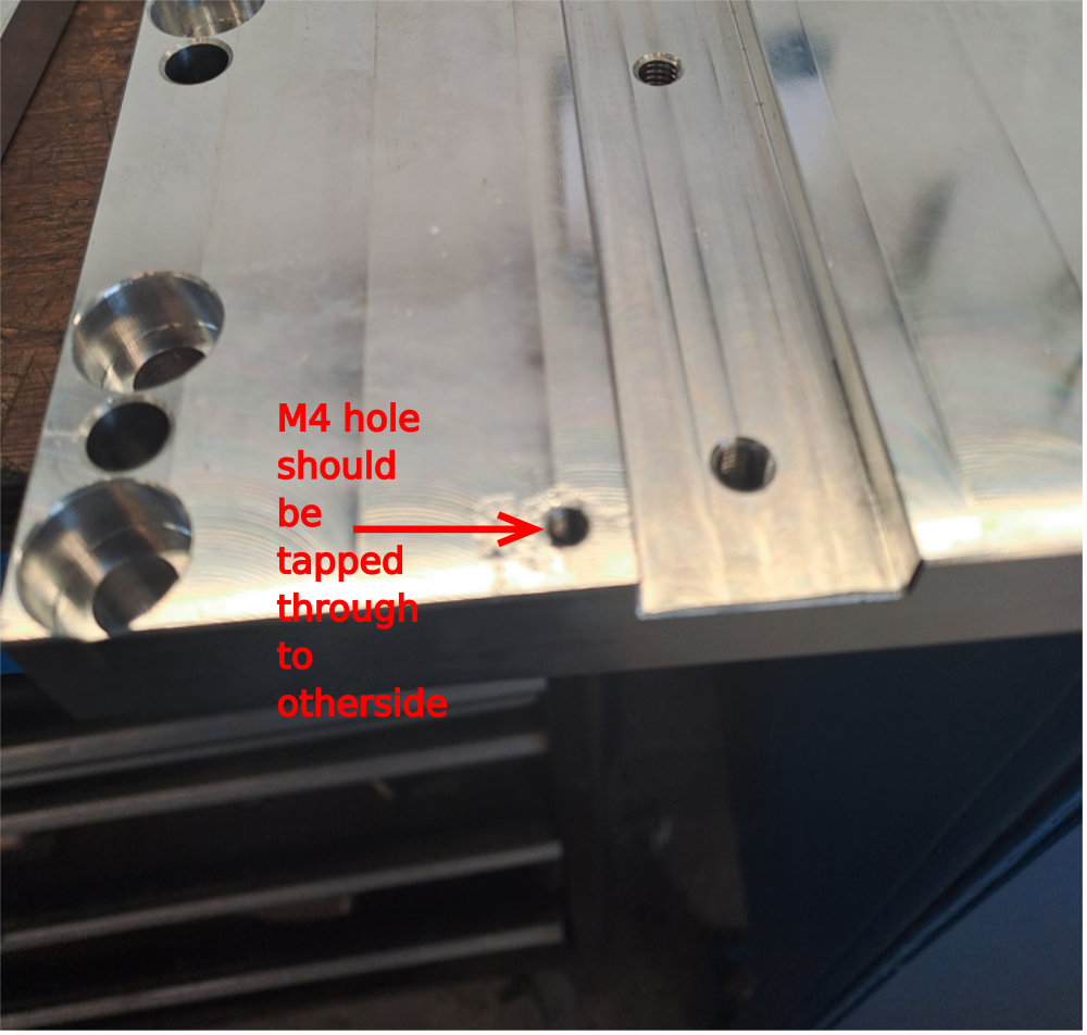
Étape 2 - Quality Check
Check D0000291 spindle base has M4 hole tapped all the way through the plate. Rework if not
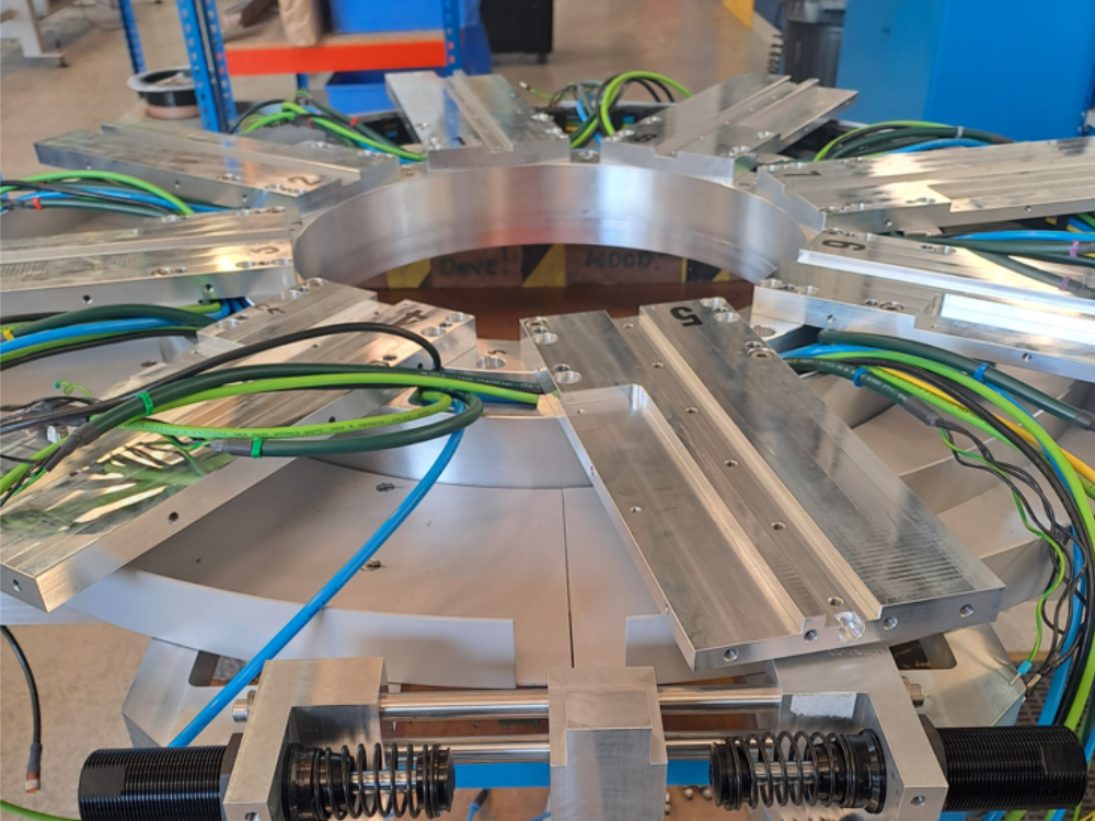
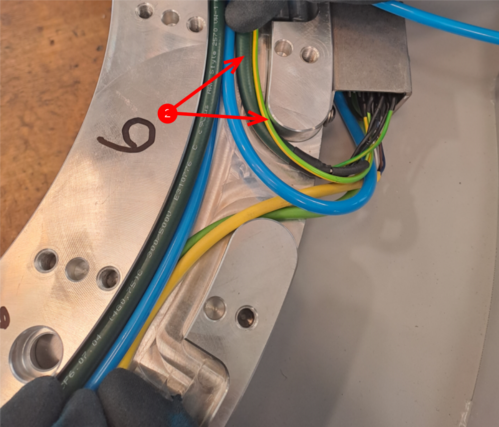
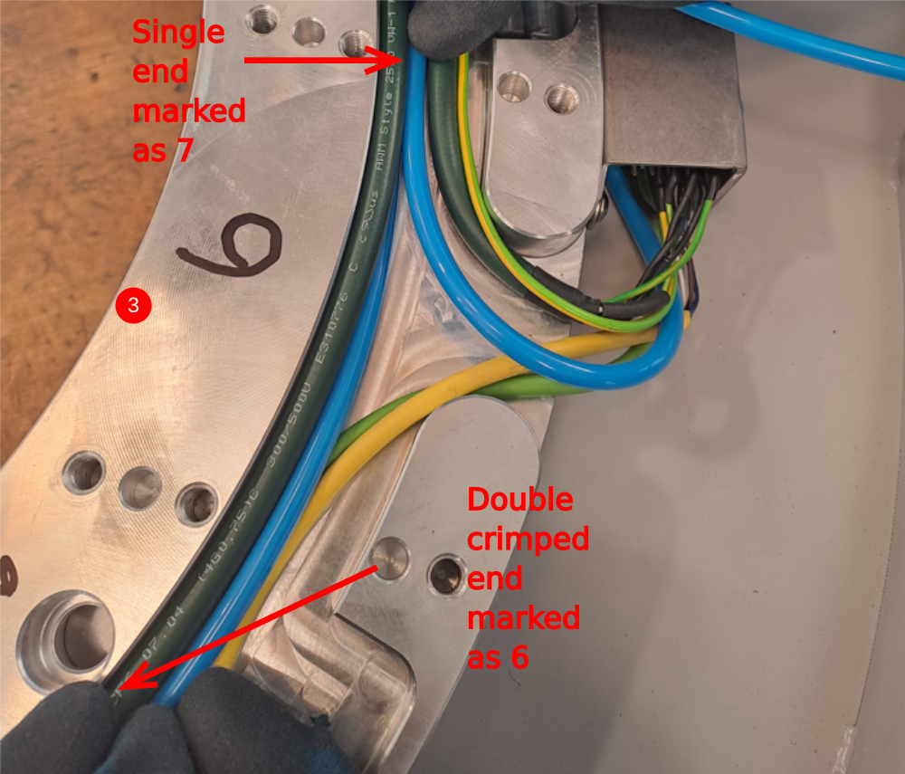
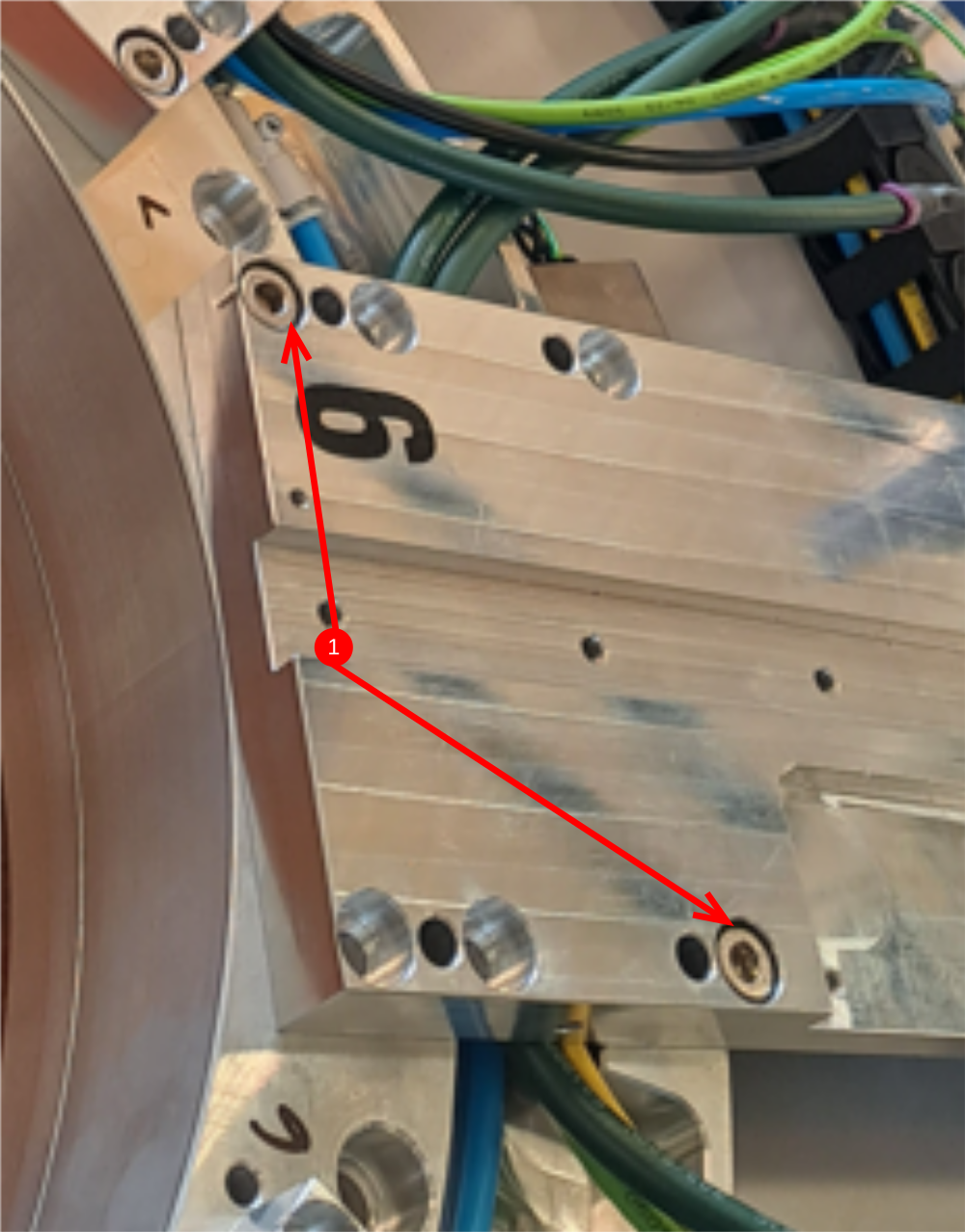
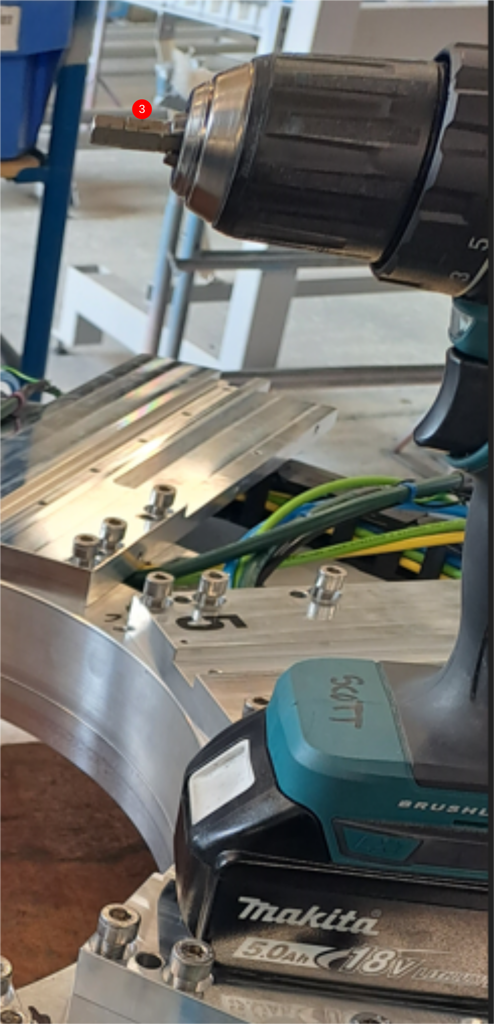
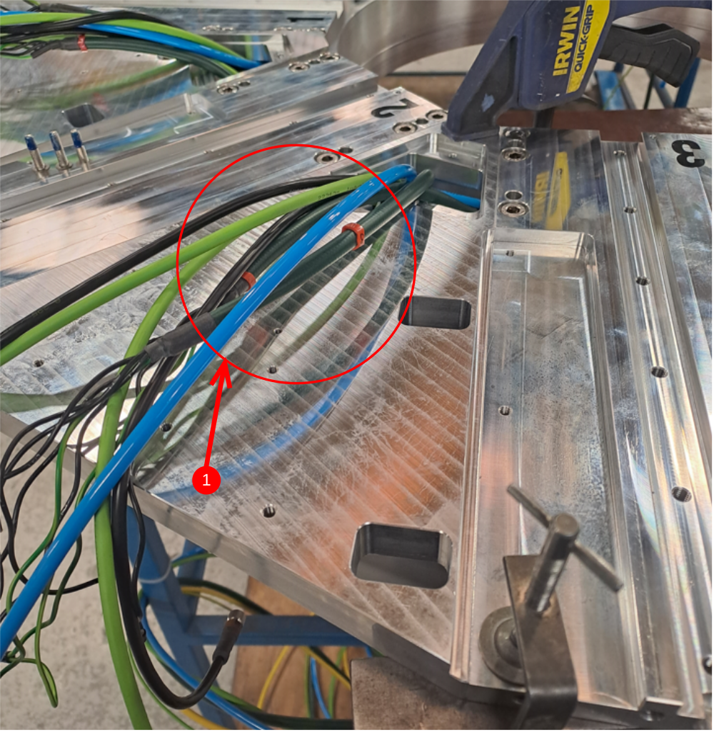
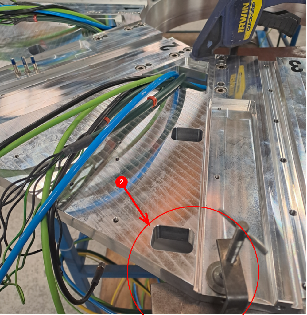
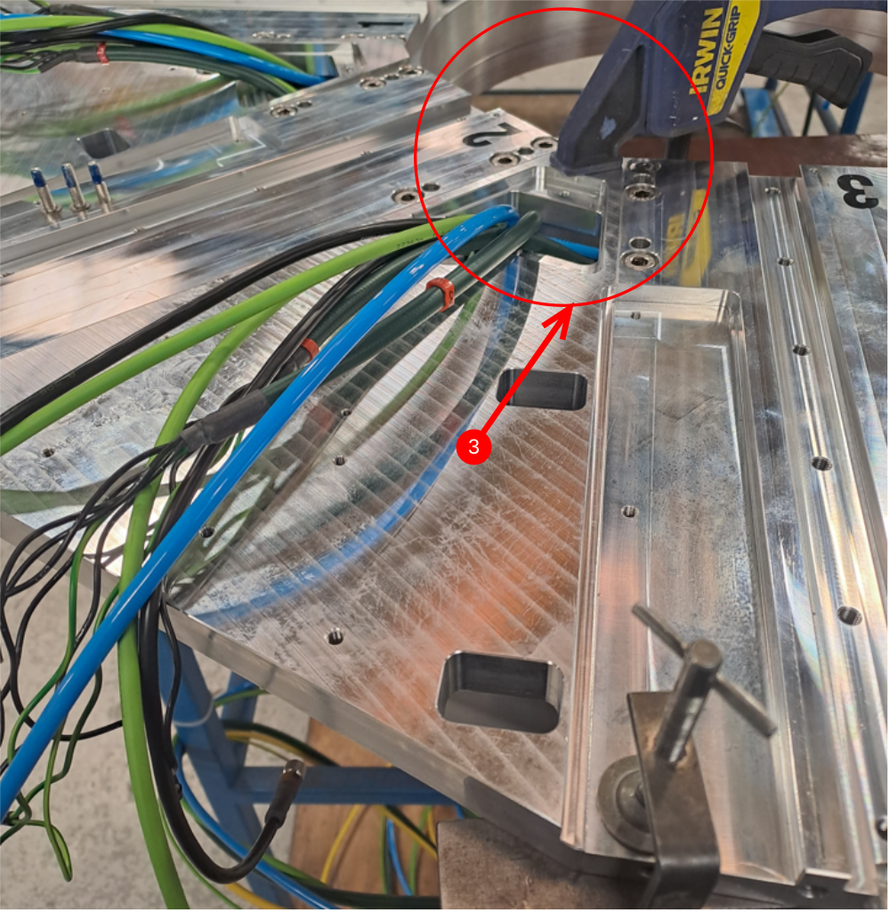
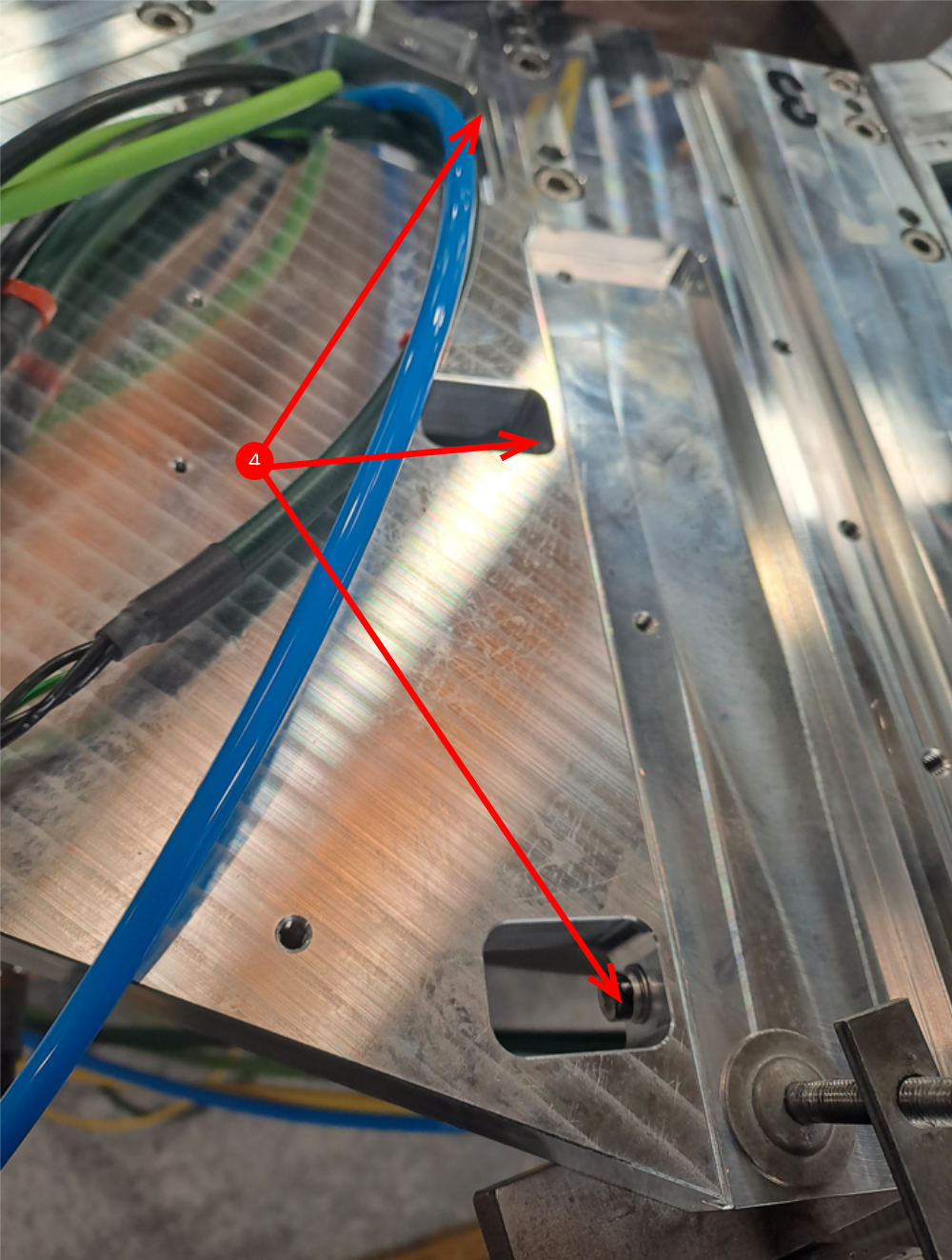
Étape 3 - Start Wiring loom installation
Wiring loom is started at position 6 as indicated by picture
1 Green and yellow Ethercat system cables route left to connection box 6
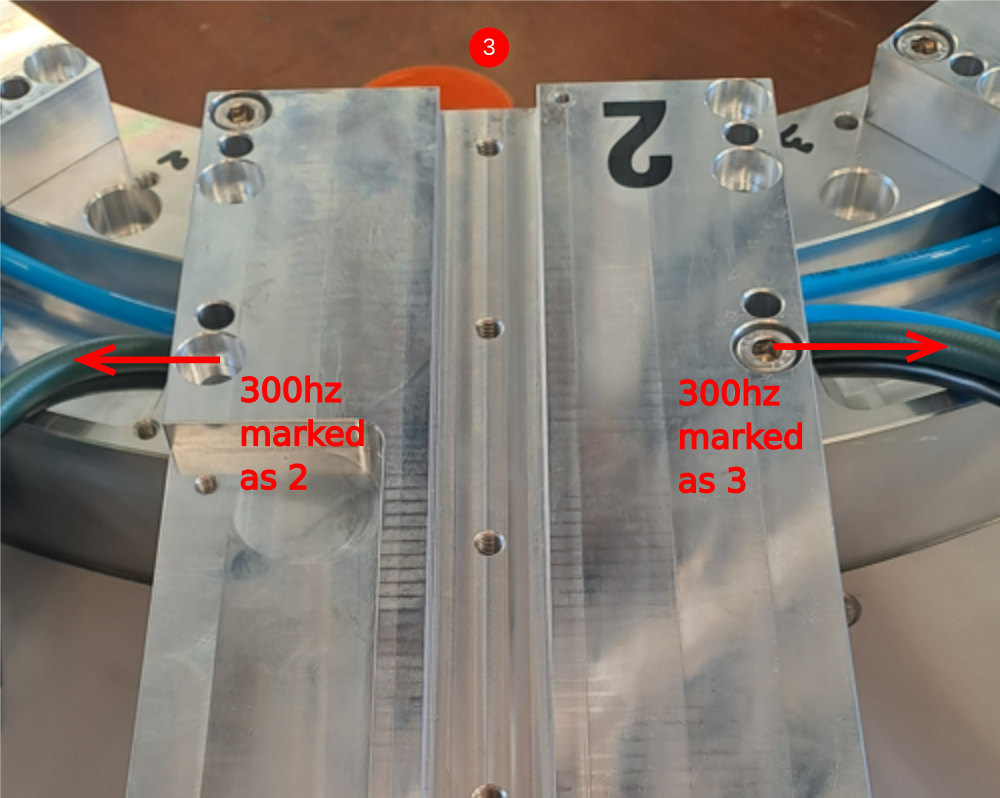
2 300 hz power cable and earth cable route to the right to connection box 7
3 Pre made 300 hz wiring loom . Identify Single end of loom marked as 7 connected to double crimped end marked as 6. Run between 7 and 6 as shown in image
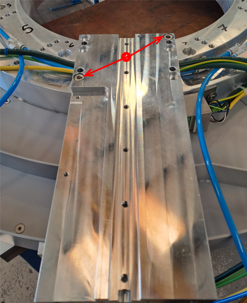
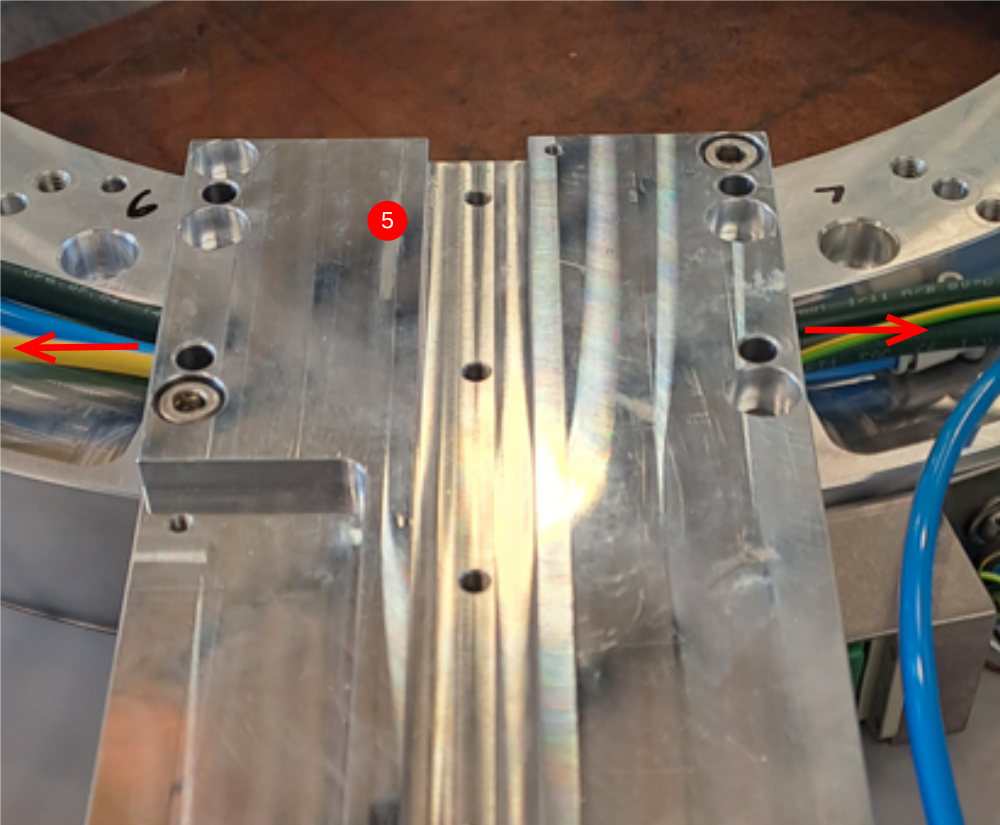
4 Fit plate D0000291 using 2 off m8 x 25 socket caps. Only apply light tension to the m8 socket caps with no adhesive .
5 Once plate is fitted, ensure cables under are not trapped by checking movement is possible in the direction shown
6 Fit M0000025 number ident
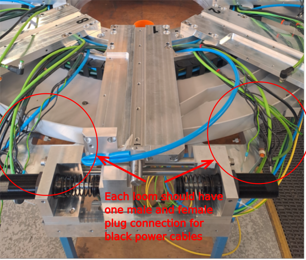
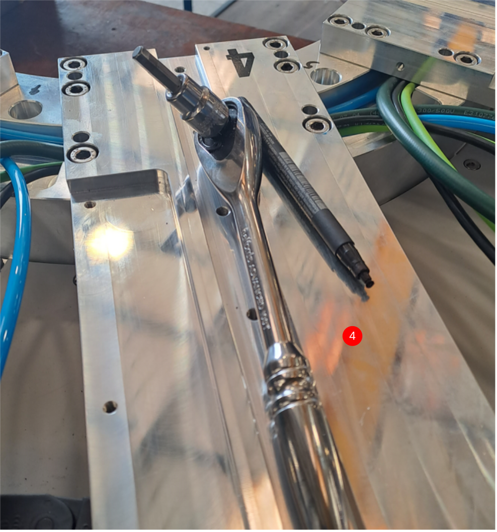
Étape 4 - Quality check power routing
Pre made power cables (ethercat power ) should be double checked for correct routing and orientation
Each spindle loom should contain one female and one male plug .
Check this is the case once loom is installed
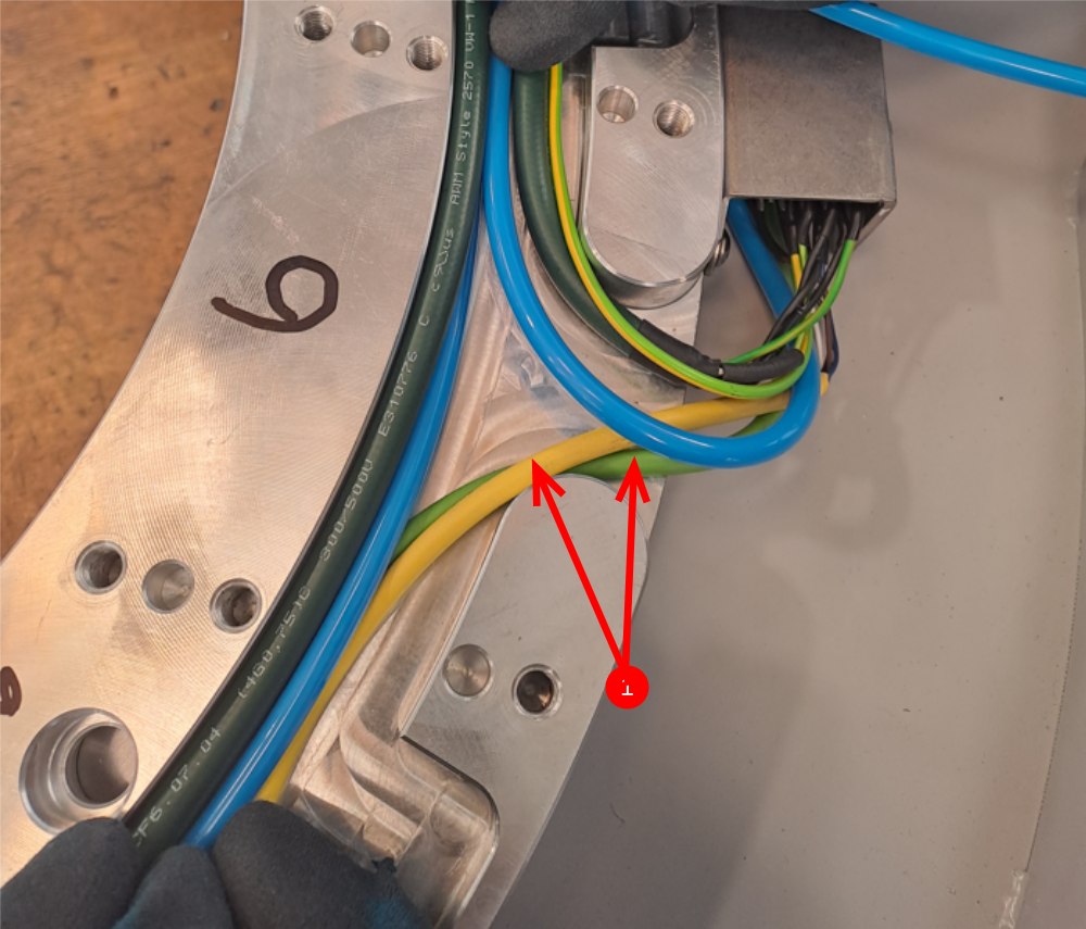
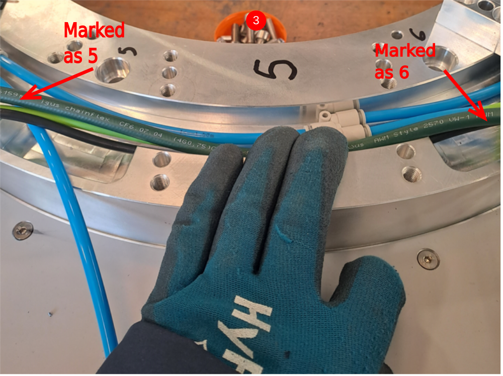
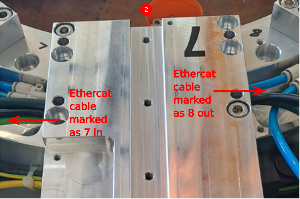
Étape 5 - Spindle 6 to 5 connections
From pre made cables, identify the following
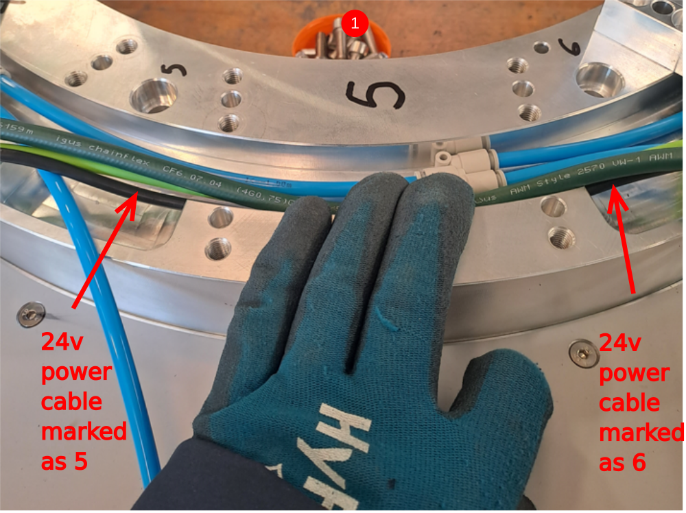
24v power cable marked as 6 and 5
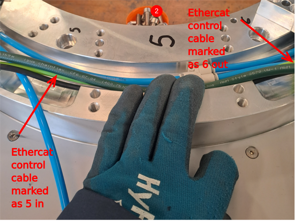
Green ethercat cable marked as 6 out - 5 in
1 Install 24v power cable as shown
2 Install green ethercat cable as shown
3 Install 300 hz power cable as shown
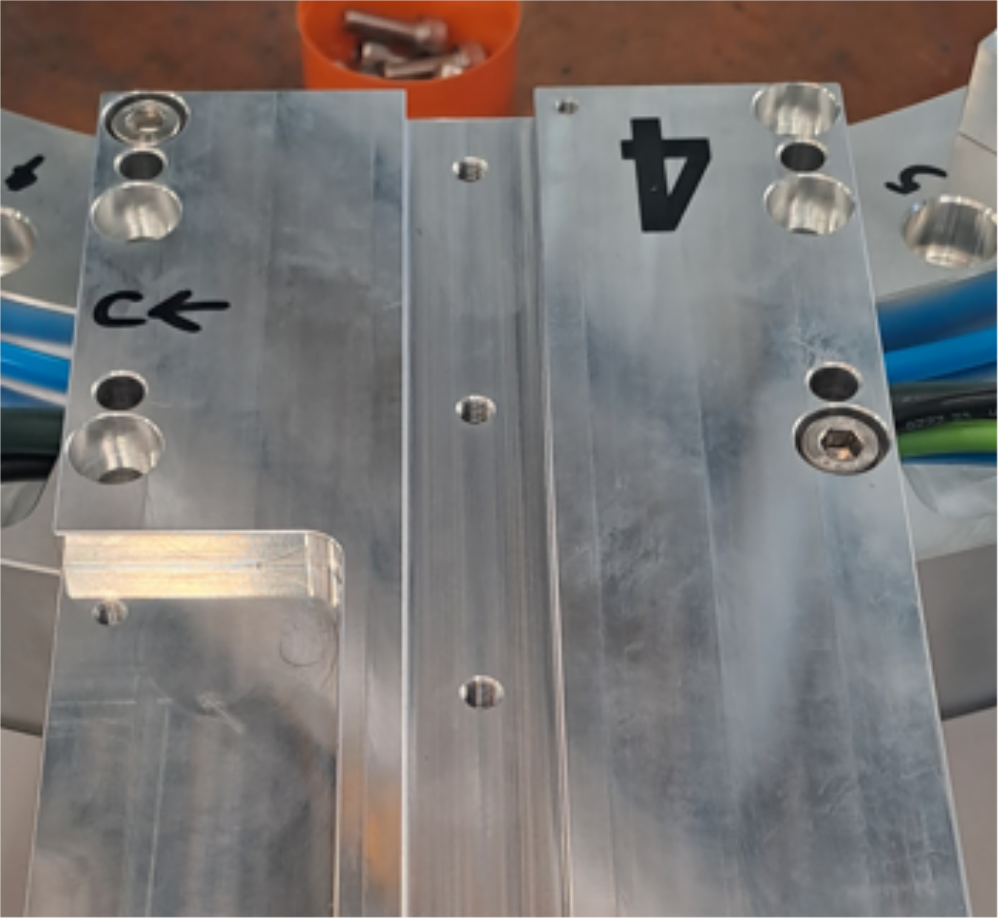
4 Attach next D0000291 plate as step 3
5 Fit M0000025 number ident

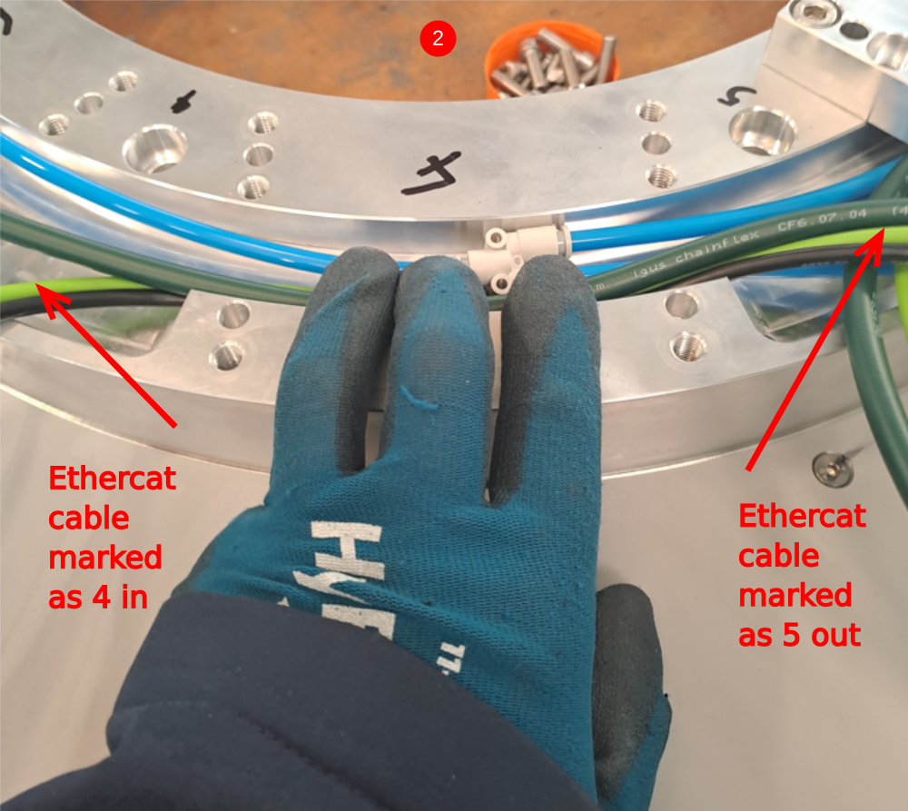
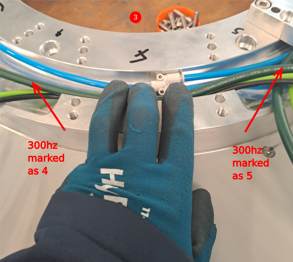
Étape 6 - Spindle 5 to 4 connections
24v power cable marked as 5 and 4
Green ethercat cable marked as 5 out - 4 in
1 Install 24v power cable as shown
2 Install green ethercat cable as shown
3 Install 300 hz power cable as shown
4 Attach next D0000291 plate as step 3
5 Fit M0000025 number ident

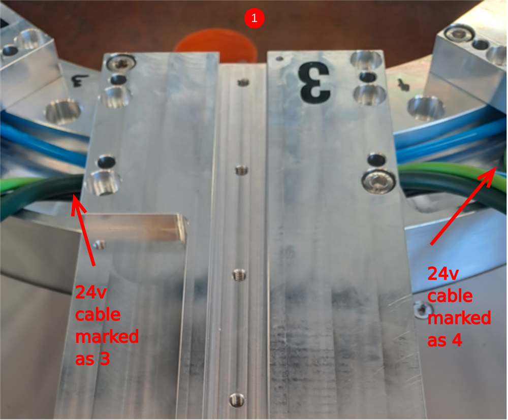
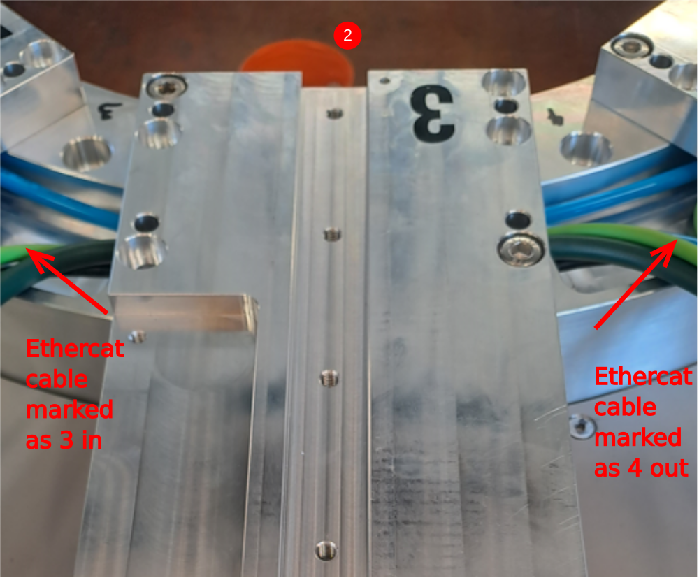
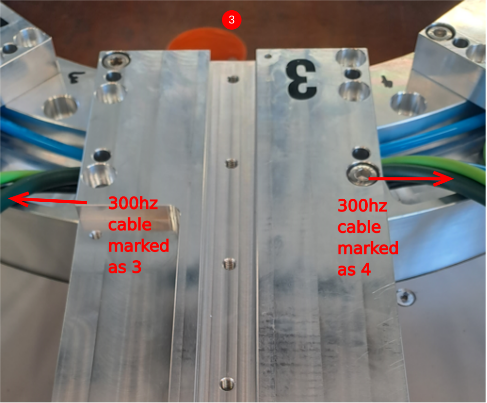
Étape 7 - Spindle 4 to 3 connections
24v power cable marked as 4 and 3
Green ethercat cable marked as 4 out - 3 in
1 Install 24v power cable as shown
2 Install green ethercat cable as shown
3 Install 300 hz power cable as shown
4 Attach next D0000291 plate as step 3
5 5 Fit M0000025 number ident

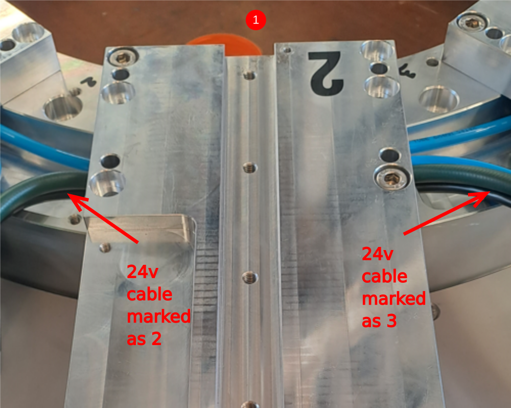
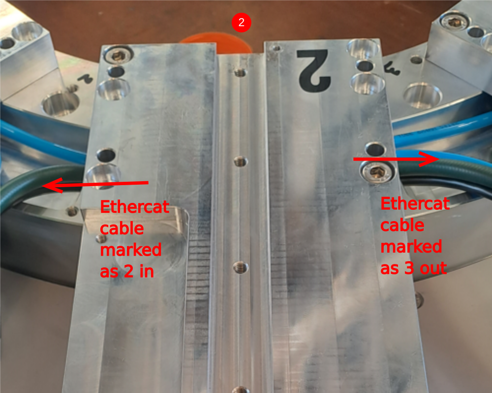
Étape 8 - Spindle 3 to 2 connections
24v power cable marked as 3 and 2
Green ethercat cable marked as 3 out - 2 in
1 Install 24v power cable as shown
2 Install green ethercat cable as shown
3 Install 300 hz power cable as shown
4 Attach next D0000291 plate as step 3
5 5 Fit M0000025 number ident

Étape 9 - Spindle 2 to 1 Connections
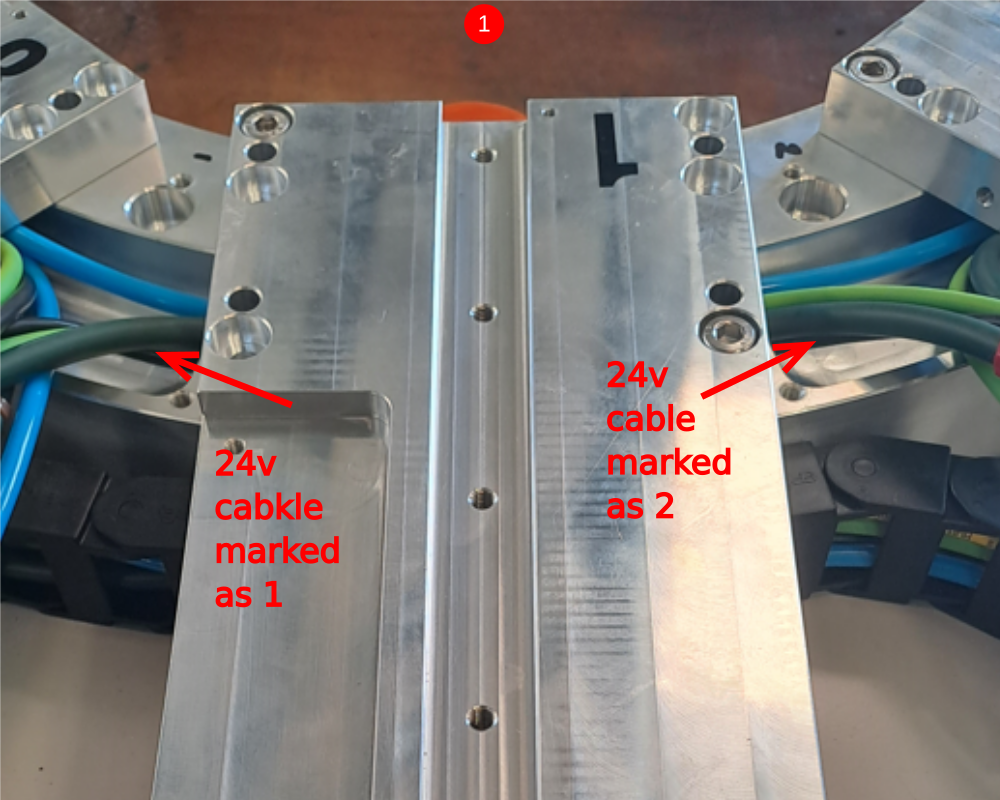
24v power cable marked as 2 and 1
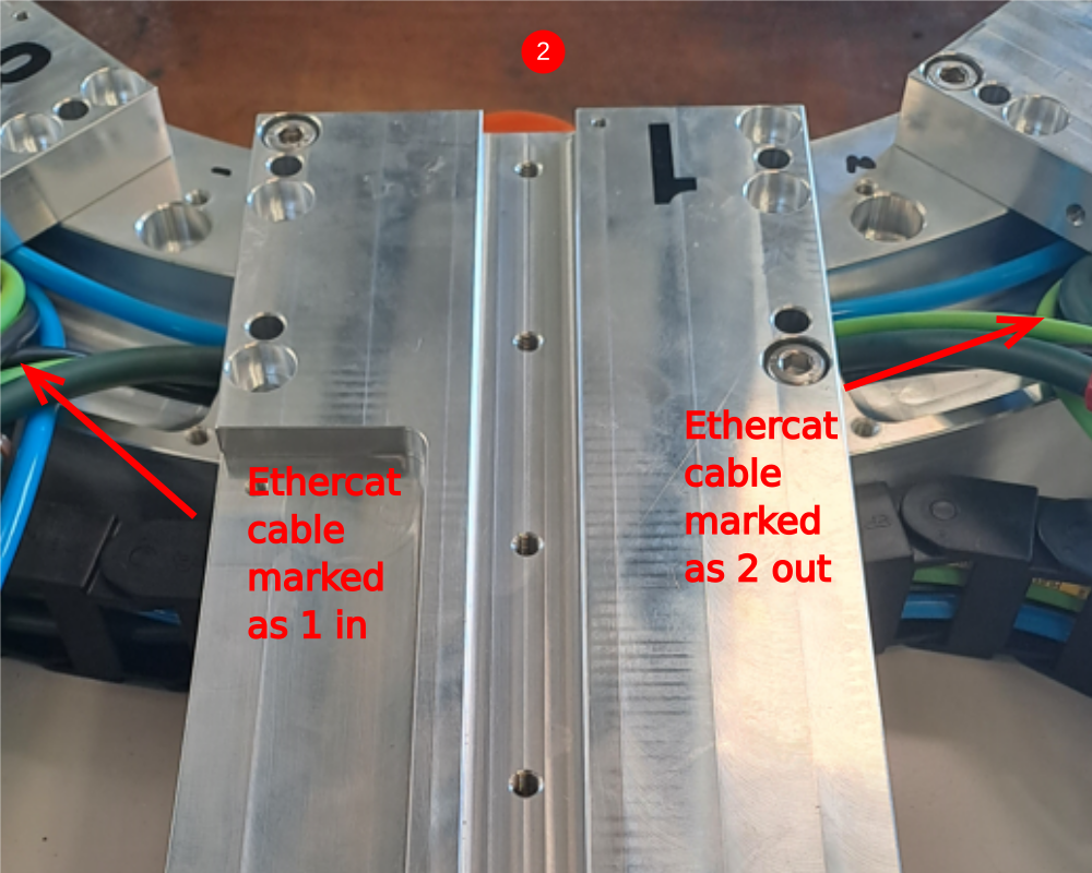
Green ethercat cable marked as 2 out - 1 in
1 Install 24v power cable as shown
2 Install green ethercat cable as shown
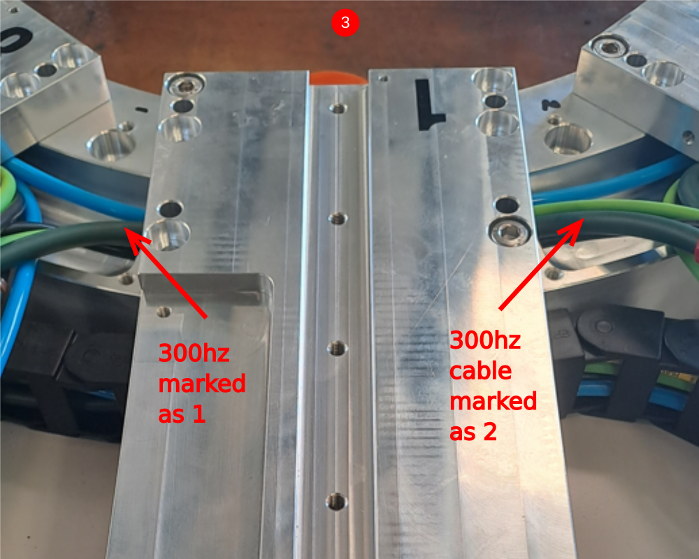
3 Install 300 hz power cable as shown
4 Attach next D0000291 plate as step 3
5 5 Fit M0000025 number ident

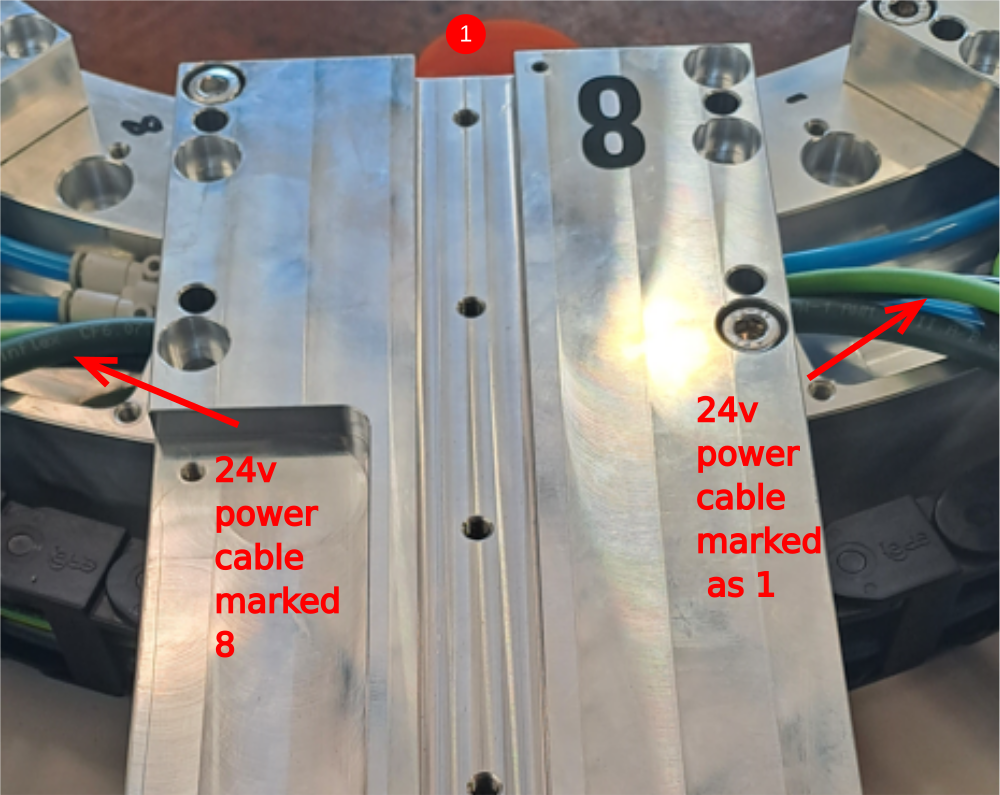
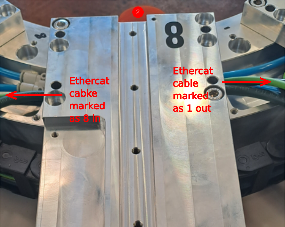
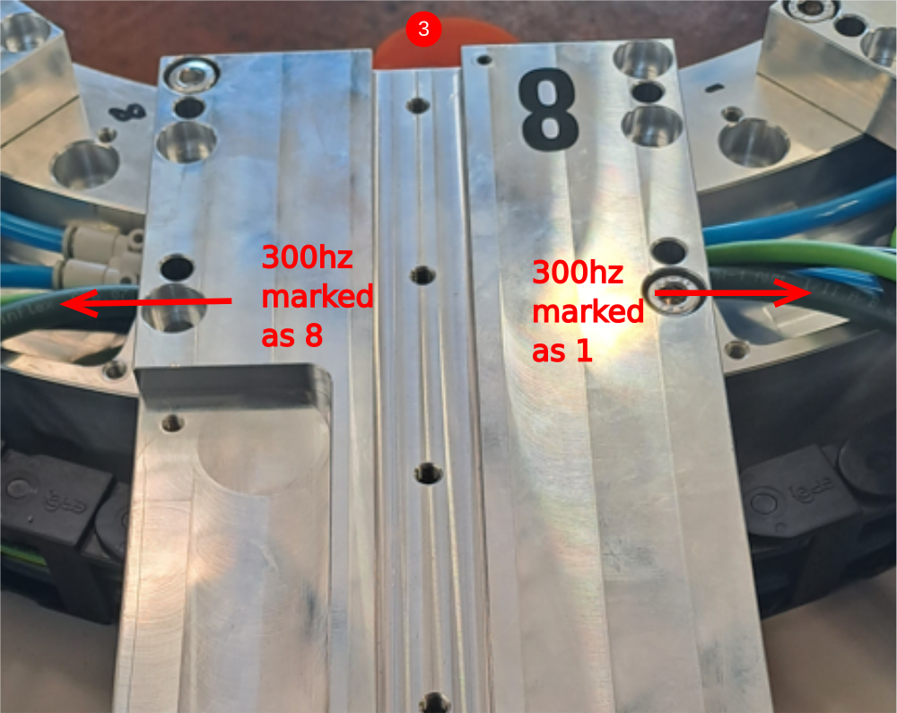
Étape 10 - Spindle 1 to 8 connections
24v power cable marked as 1 and 8
Green ethercat cable marked as 1 out - 8 in
1 Install 24v power cable as shown
2 Install green ethercat cable as shown
3 Install 300 hz power cable as shown
4 Attach next D0000291 plate as step 3
5 5 Fit M0000025 number ident

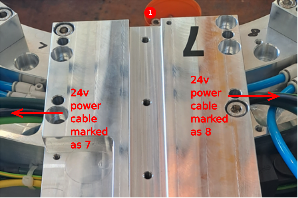
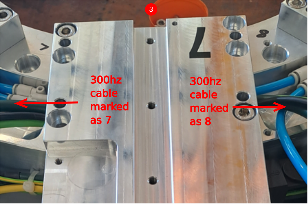
Étape 11 - Spindle 8 to 7 connections
24v power cable marked as 8 and 7
Green ethercat cable marked as 8 out - 7 in
1 Install 24v power cable as shown
2 Install green ethercat cable as shown
3 Install 300 hz power cable as shown
4 Attach next D0000291 plate as step 3
5 5 Fit M0000025 number ident

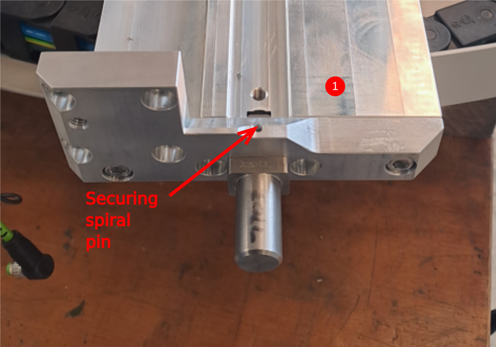
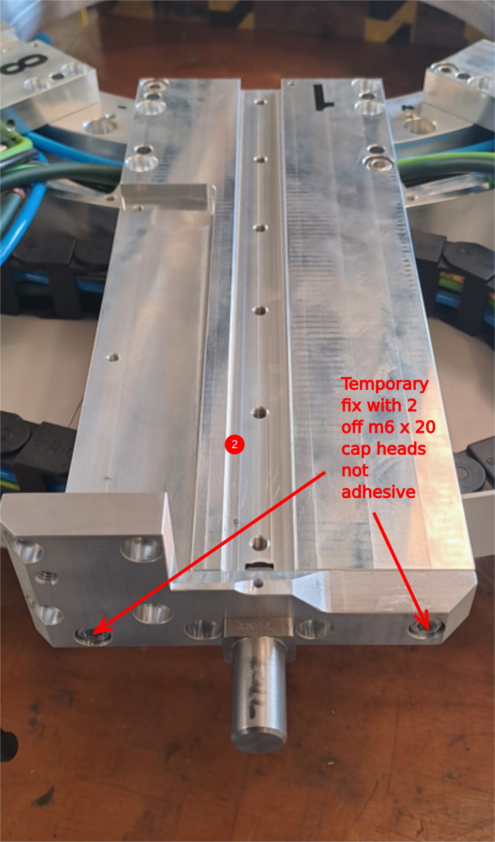
Étape 12 - Fit datum stop pin assembly to spindle plate
1 Assemble D0007990 cylinder anchor and D0007703 datum pin. Use
3mm x 26mm roll pin to secure together
2 Temporary fix to spindle plate with m6 x 20 socket caps
Étape 13 - Fit assembled R axis stop R0000713E
1 Fit r axis limit stop to main assembly . Use 6 off m8 x 40 socket caps with A form washers
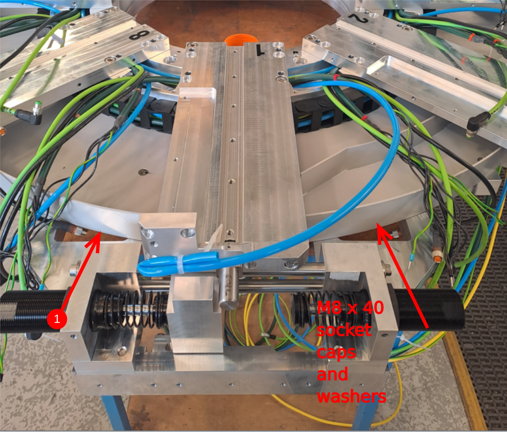
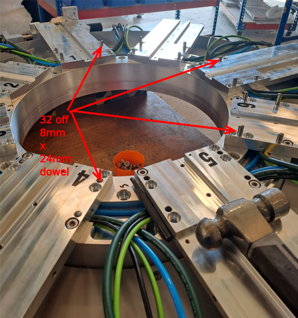
Étape 14 - Dowel D0000291 plates in position
Add 4 off 8mm x 24mm dowels to each spindle by hand to start . Use and hammer and drift to drive down dowel until it bottoms out in blind hole
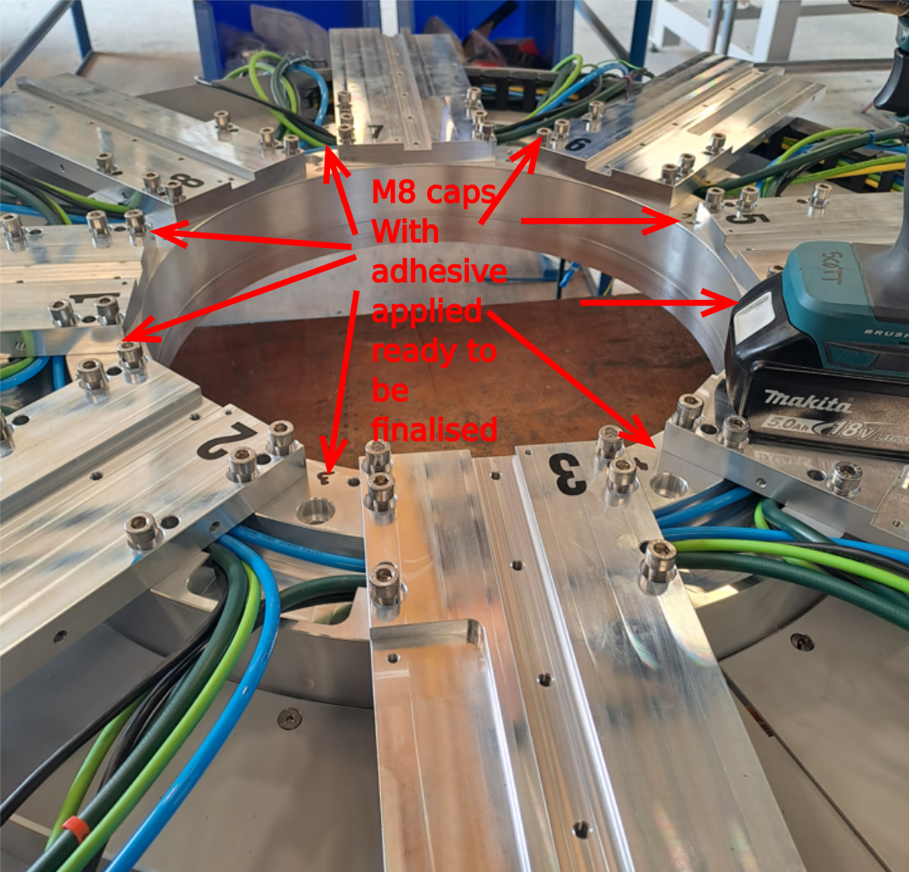
Étape 15 - Add fixings
1 Remove 2 off m8 x 25mm cap heads from each spindle plate
2 Apply adhesive and lay M8 x 25 cap heads in ALL spindle holes ready for fixing
3 Use drill driver with 6mm hex bit to drive all cap heads in. Set clutch to 14
4 Methodically apply final tension to bolt by hand and mark as complete
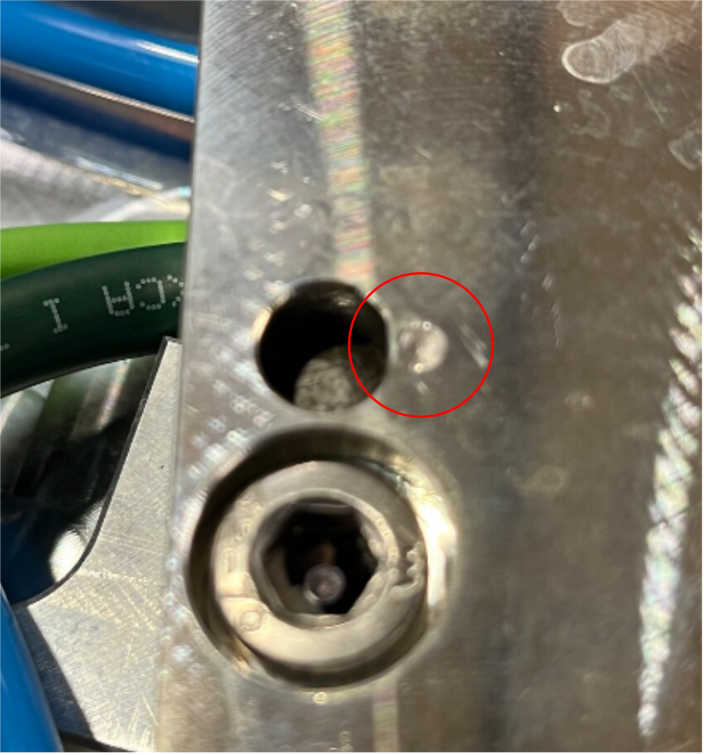
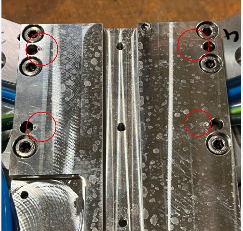
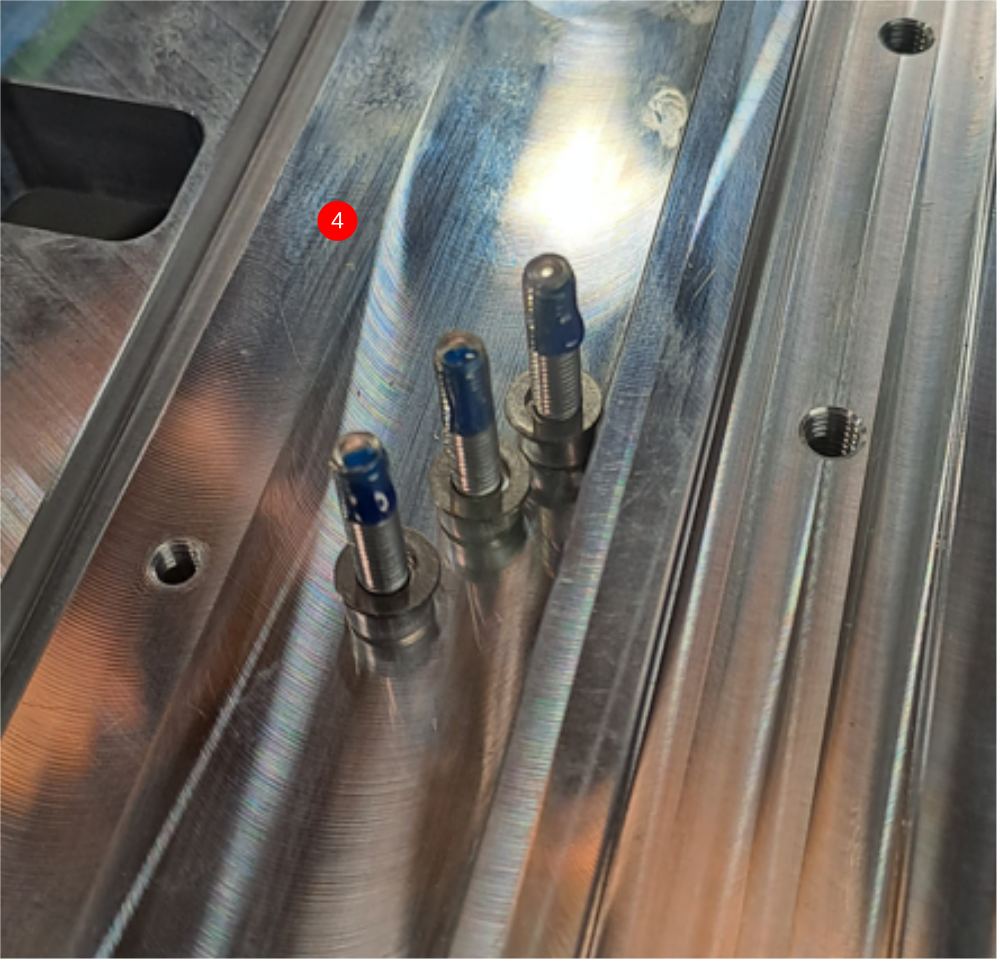
Étape 16 - Finalize dowel holes
Once spindles are final fixed, preventative prep must be added to dowel holes to stop slip of dowel from hole.
Add 1 off centre dot to each dowel position to slightly swage over top of hole
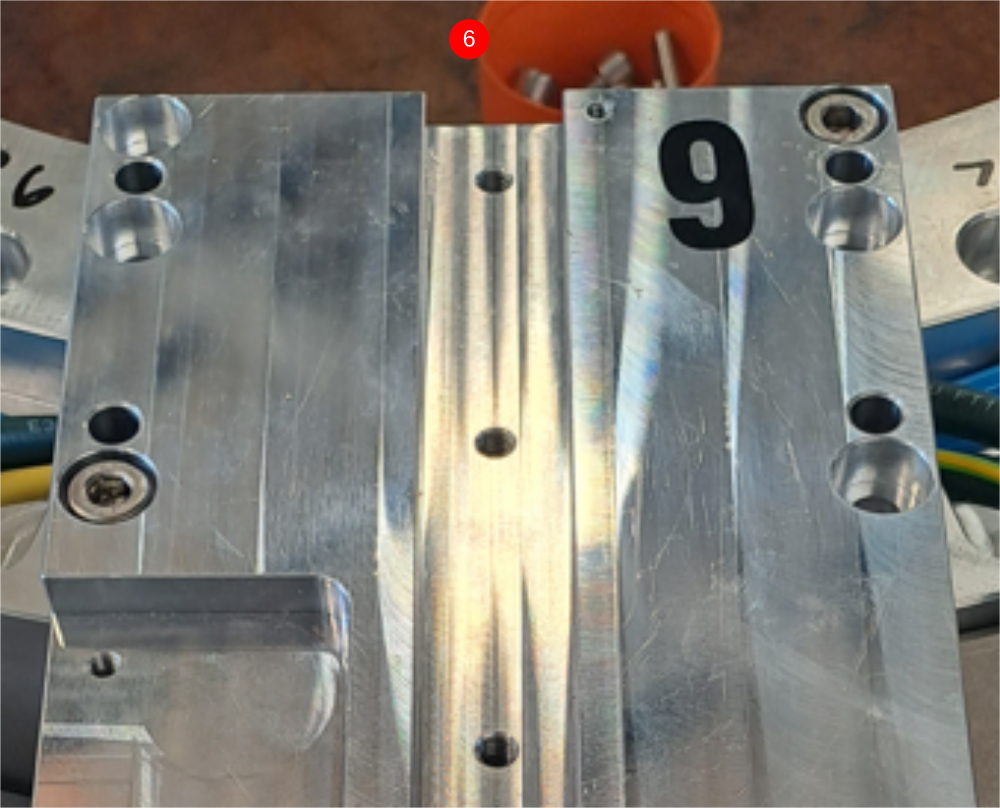
Étape 17 - Add Spindle infill plates
Add D0007611 infill plates to spindle plates 1,3,5 and 7
Add D0001176 infill plates to spindles 2,4,6 and 8
1 Place spindle infill plate in position threading through exiting cables
2 Place support block and small g clamp at position shown
3 Fit quick clamp to pin infill plate to ring base
4 Fit 3 off M5 x 20 socket caps With M5 A form washers to attach plate . Use a reduced length 4mm key for this
Repeat for all eight spindle plates

Draft
 Français
 English
 Deutsch
 Español
 Italiano
 Português