Details for mounting cylinder rails to transfer beams

Difficulté
Moyen
Durée
8 heure(s)
Sommaire
- 1 Introduction
- 2 Étape 1 - Unless otherwise stated
- 3 Étape 2 - Position pre built cylinder rails
- 4 Étape 3 - Adjust delrin wheels front
- 5 Étape 4 - Adjust Delrin wheels Rear
- 6 Étape 5 - Check all fasteners
- 7 Étape 6 - Check movement
- 8 Étape 7 - Cylinder heights checked on all areas
- 9 Étape 8 - Set rack meshing
- 10 Étape 9 - Check for clearance
- 11 Étape 10 - Caution
- 12 Étape 11 - Start setup on Cylinder rail 1
- 13 Étape 12 - Set rack mesh 1
- 14 Étape 13 - Set Rack mesh point 2
- 15 Étape 14 - Repeat steps 10 and 11
- 16 Étape 15 - Align Cylinders to Hepco
- 17 Étape 16 - Attach pneumatic jig
- 18 Étape 17 - Set wire line
- 19 Étape 18 - Adjust cylinder rails 2-7
- 20 Étape 19 - Quality check
- 21 Étape 20 - Finalise drive pinions
- 22 Étape 21 - Add Hard stops
- 23 Étape 22 - Delrin wheel Quality check
- 24 Étape 23 - Quality sign off
- 25 Étape 24 - Quality sign off
- 26 Étape 25 - Warning
- 27 Commentaires
Introduction
Tools Required
Standard spanner set
Standard hex key set
Tape measure
Wire line
Pneumatic cylinder setting jig
Parts Required
R0015288 Bench Assemble Transfer slid units and cylinder rails
Étape 1 - Unless otherwise stated
Use Loctite 243 on all fasteners
Use Loctite 572 on all threaded pneumatic connection
Pen mark all fasteners to show finalised

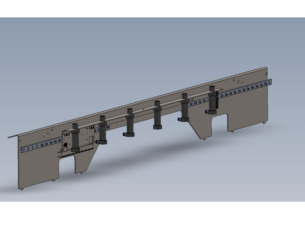
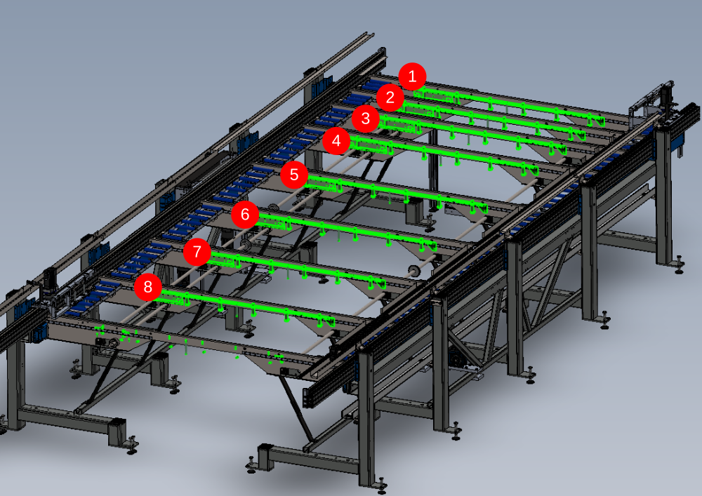
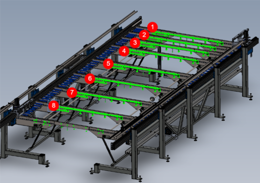
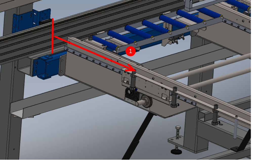
Étape 2 - Position pre built cylinder rails
Position Cylinder rail onto transfer beam as shown

Étape 3 - Adjust delrin wheels front
Remove safety bolt stop from cylinder rails
Adjust delrin wheels on section shown
Ensure to use Setting Delrin Transfer Table Wheel Tension To set delrin wheels correctly

Étape 4 - Adjust Delrin wheels Rear
Adjust delrin wheels on section shown
Ensure to use Setting Delrin Transfer Table Wheel Tension To set delrin wheels correctly

Étape 5 - Check all fasteners
Check all fasteners are correctly tensioned
Ensure all delrin wheels are correctly set and all fasteners on delrin wheels are tensioned to final tension

Étape 6 - Check movement
Ensure cylinder rail is free moving along transfer beam
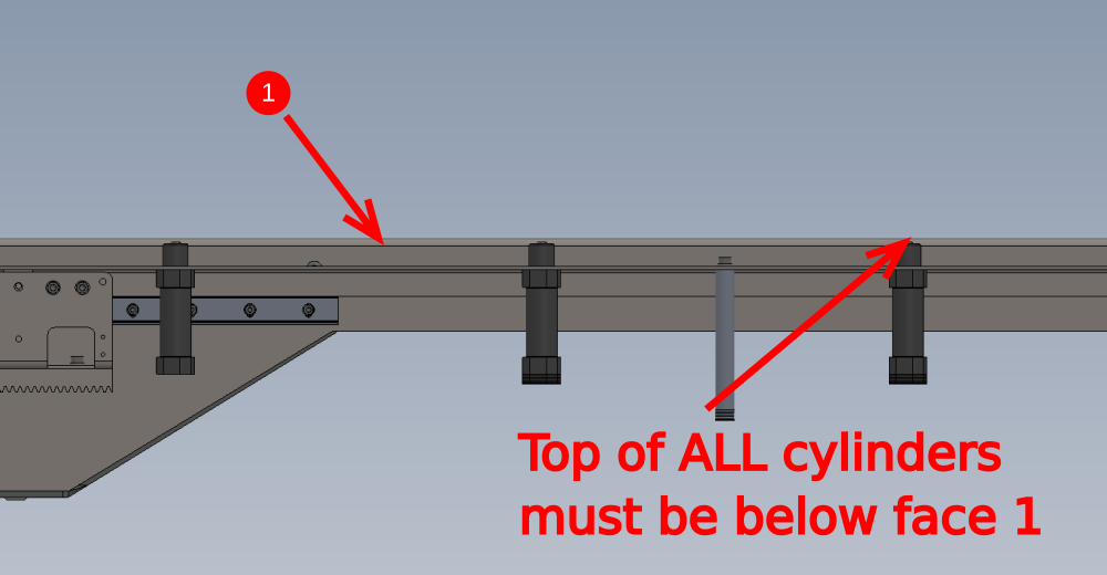
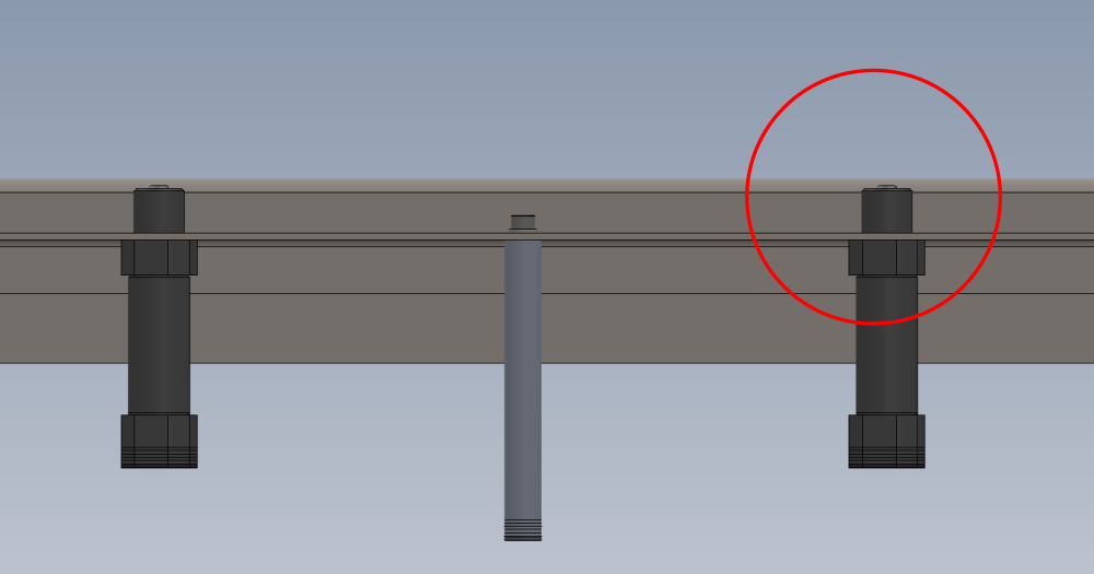
Étape 7 - Cylinder heights checked on all areas
All cylinders should be checked for correct height position in regards to top face of transfer arms
All cylinders should be below the top face of the transfer arm,
Check with 2 meter straight edge over tops of transfer arms


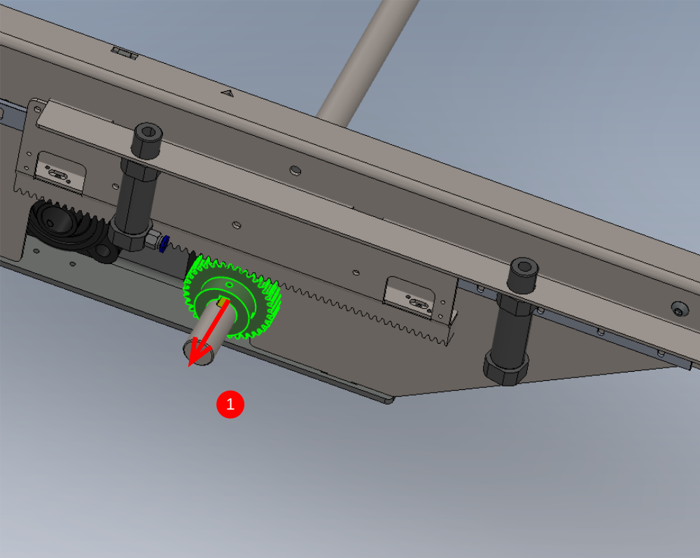
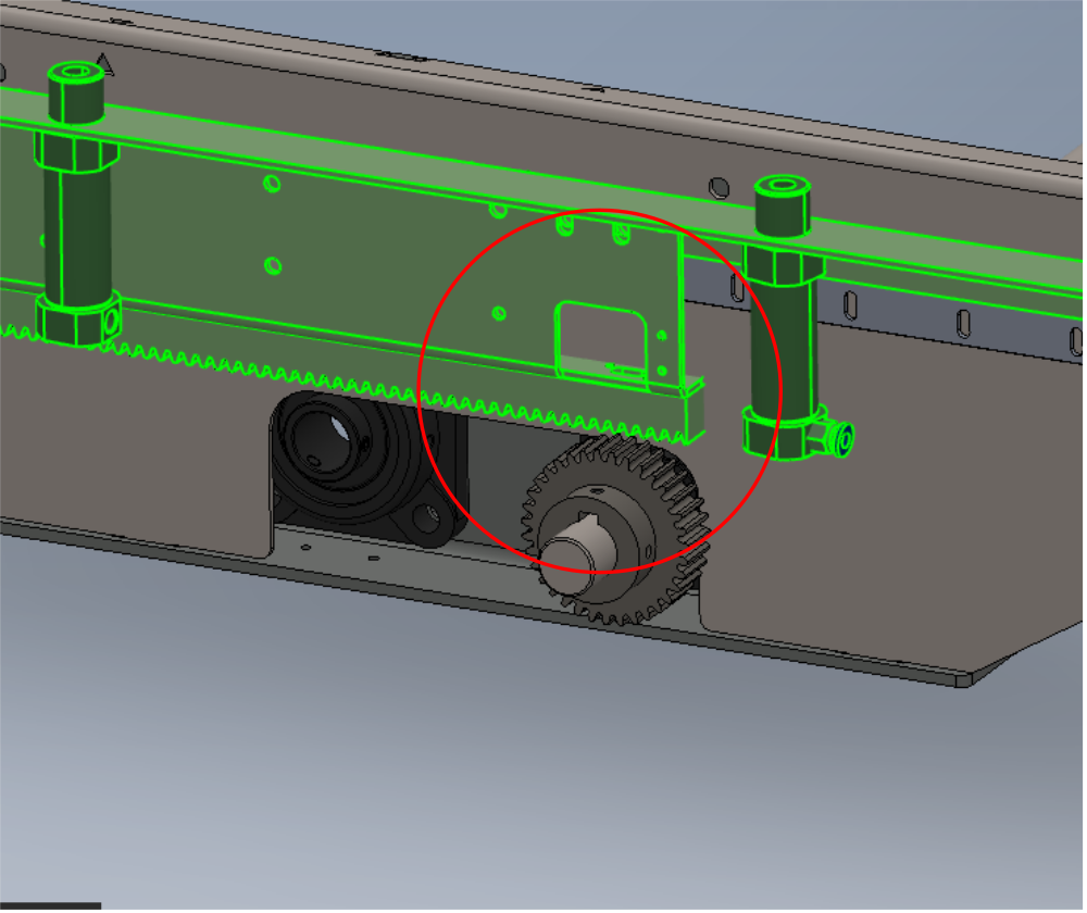
Étape 8 - Set rack meshing
Mesh requires setting between slider unit and drive pinion
It is vital that the correct drive meshing is achieved.
Complete the following steps to mesh pinion and drive correctly


Étape 9 - Check for clearance
Once drive racks have been set, it is vital to check that no interference between rack and arm is present. Move racks along full length of travel and check for any fouling

Étape 10 - Caution

Étape 11 - Start setup on Cylinder rail 1

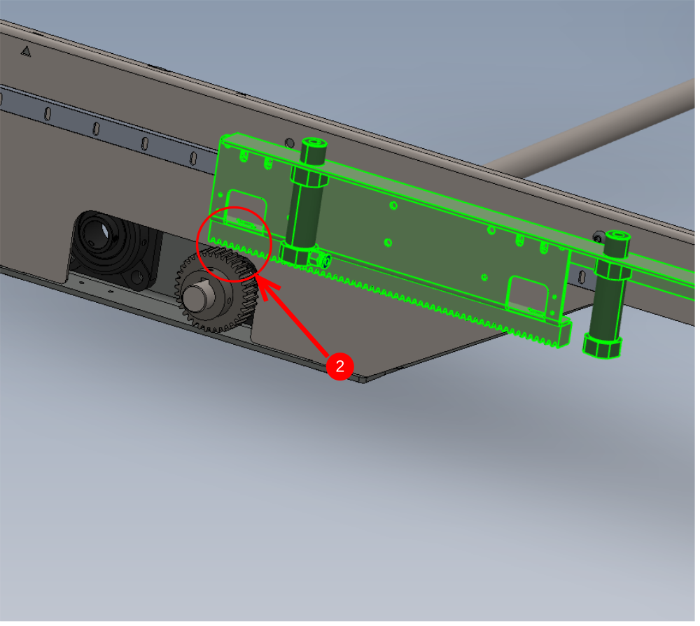
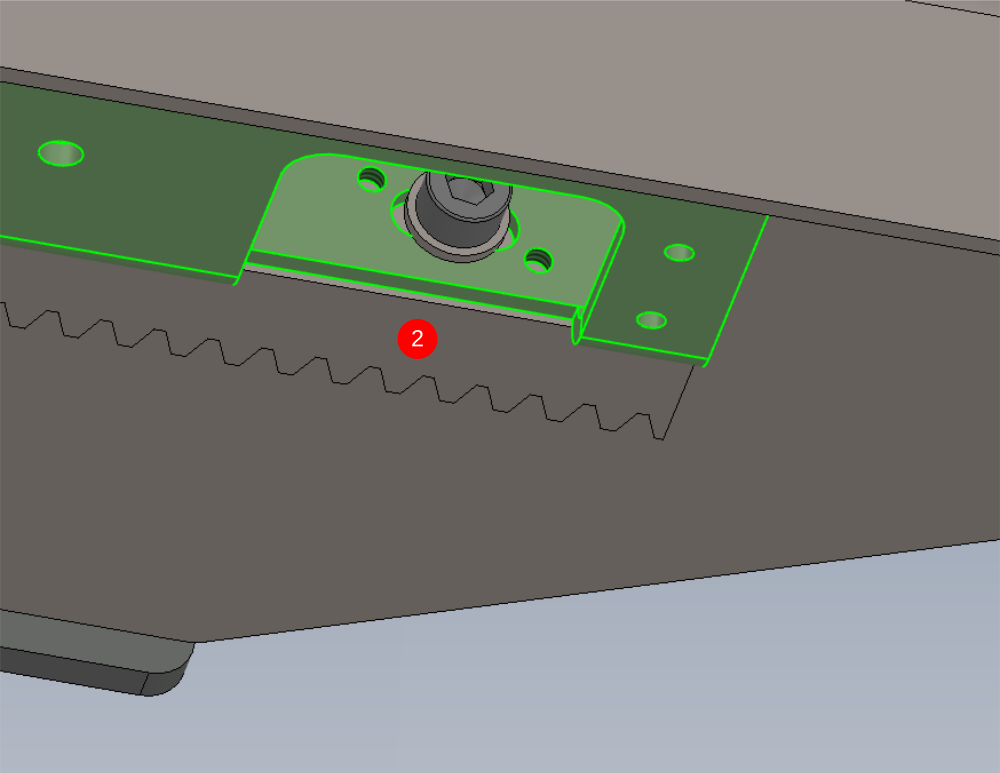
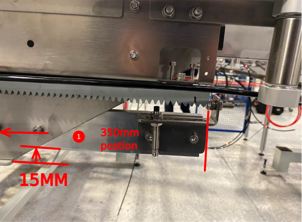
Étape 12 - Set rack mesh 1
1 Slide drive pinion away from rack , this pinion shou. be loose and free moving
2 Move cylinder rail to position shown
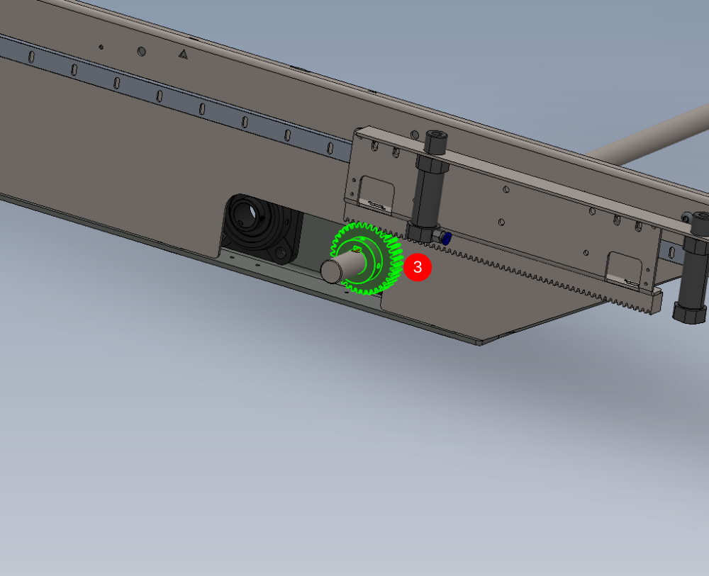
3 Slide Pinion into position under drive rack
4 Adjust Backlash between rack and pinion to give no more than 1mm movement

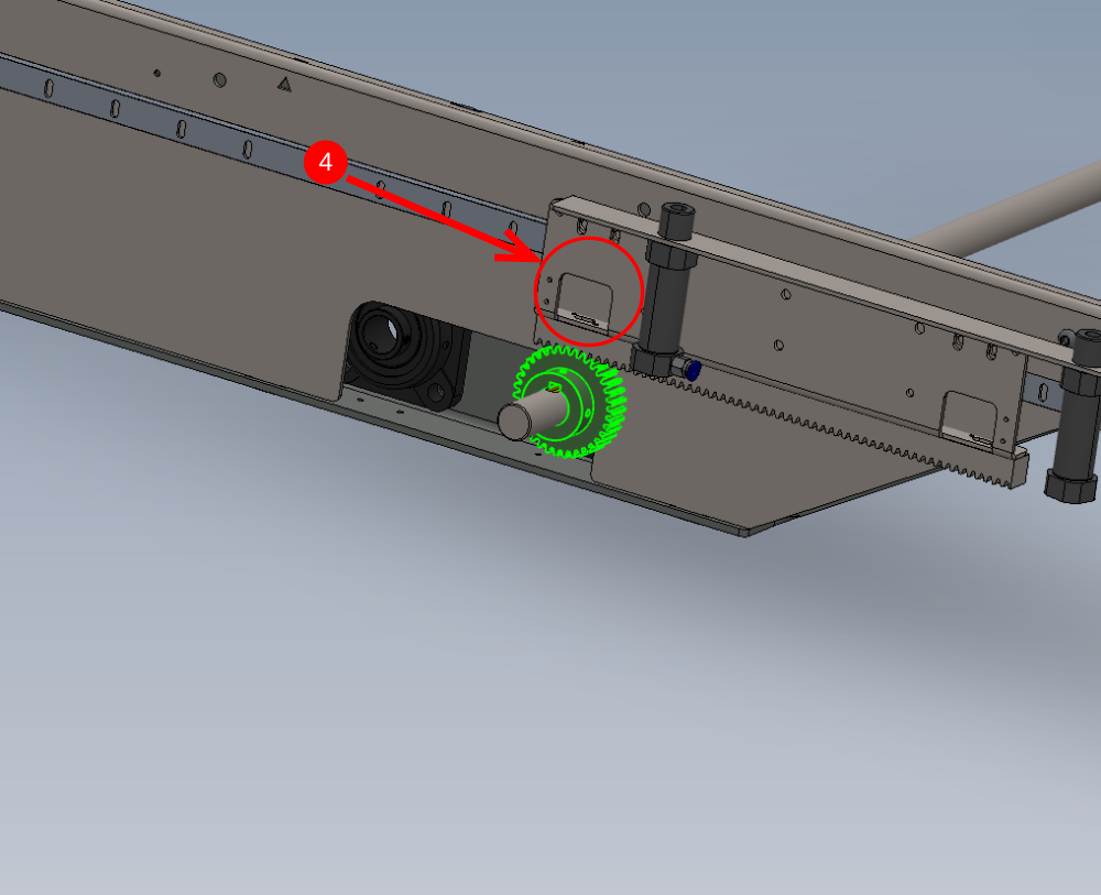
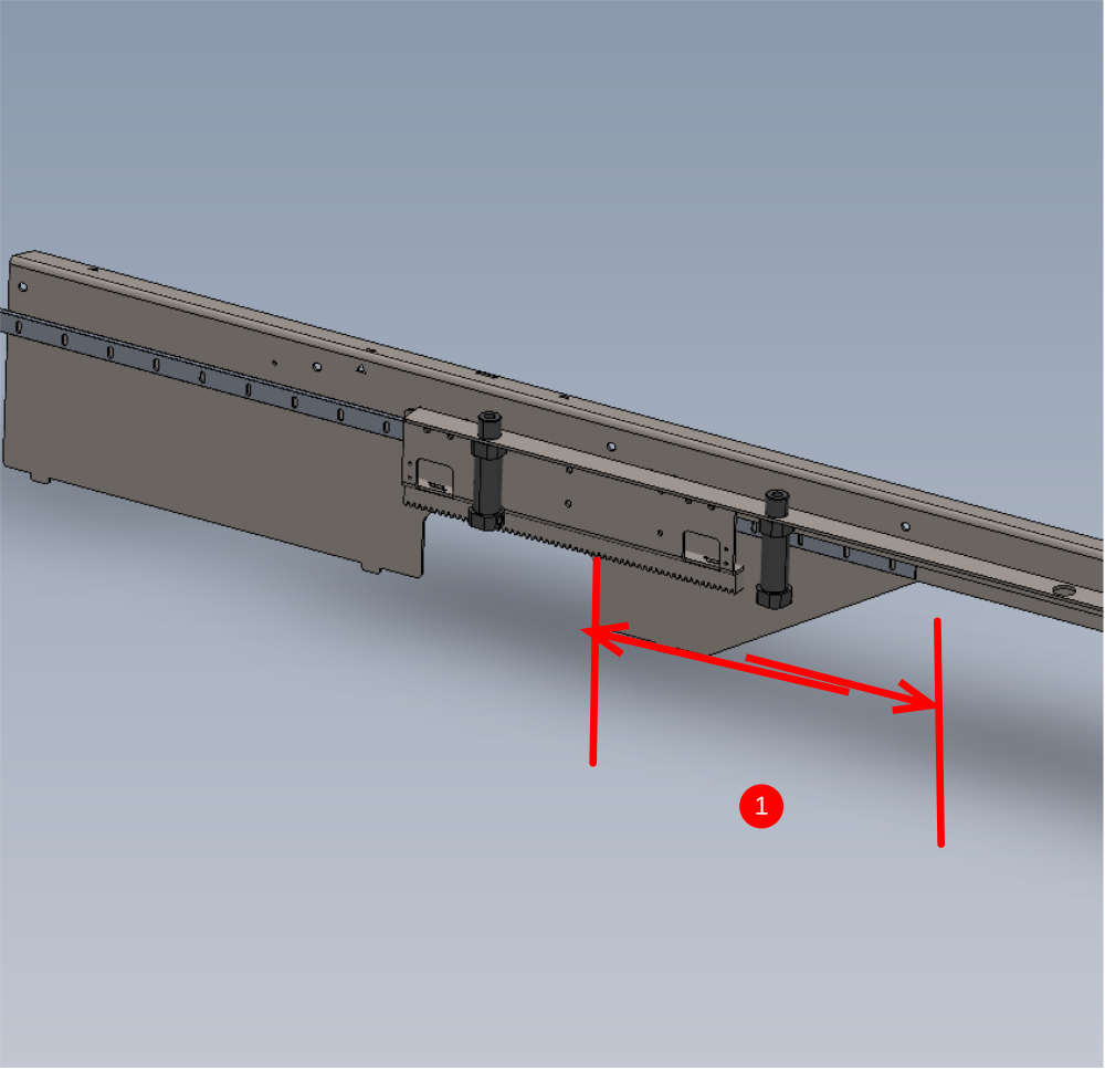
Étape 13 - Set Rack mesh point 2
Repeat step 10 but with rack in position shown

Étape 14 - Repeat steps 10 and 11
Repeat steps 10 and 11 for remain 7 off cylinder rails 2-8
Étape 15 - Align Cylinders to Hepco
Set cylinder rails to hepco rail by completing the following steps
1 Set cylinder rails 1 and 8 to same measurement to hepco beam, using same technique of sliding drive pinion out of the way to enable movement
2 For finer tuning of position, Use slots in rack mounting and drive gear position to adjust

Étape 16 - Attach pneumatic jig
Attach pneumatic jig to cylinders , to enable cylinder pistons to be extended

Étape 17 - Set wire line
Set wire line between set cylinders 1 and 8
Étape 18 - Adjust cylinder rails 2-7
Using the same method, position the remaining cylinder assemblies to the wire line
Étape 19 - Quality check
Double check setting by measuring from cylinder piston to hepco rail on each cylinder assembly
All measurements should be the same -+ 0.5mm
Étape 20 - Finalise drive pinions
Remove, apply adhesive and finalise 2 off M6 grubscrew per each drive pinion

Étape 21 - Add Hard stops
Fit hard stop assemblies once alignment is set
Fasteners and size required

Étape 22 - Delrin wheel Quality check
Once all settings have been set, Delrin wheel tension should be rechecked before final sign off
All delrin wheels should be set and be able to be stopped from rotating when held with light finger pressure. . Ensure all delrin wheels are checked on transfer assembly to ensure correct setting
Étape 23 - Quality sign off
Sign off Required for all alignment settings
Étape 24 - Quality sign off
Sign off Required for all alignment settings
Étape 25 - Warning
The next step is vital. Please ensure this is not missed again
Draft
 Français
 English
 Deutsch
 Español
 Italiano
 Português