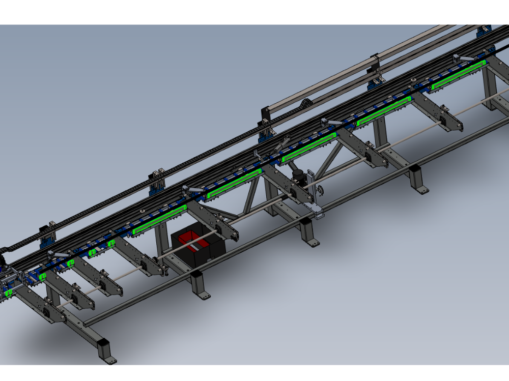
Procedure for correct alignment of module E back fences

Difficulté
Difficile
Durée
2 heure(s)
Sommaire
- 1 Introduction
- 2 Étape 1 - Unless otherwise stated
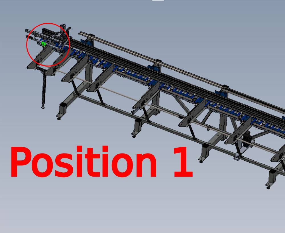
- 3 Étape 2 - Set position 1
- 4 Étape 3 - Measure Position 1
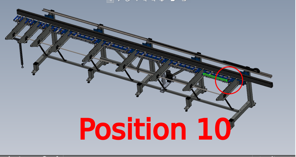
- 5 Étape 4 - Set position 10
- 6 Étape 5 - Add wire line to backfences
- 7 Étape 6 - Ensure only positions 1 and 10 are contacting
- 8 Étape 7 - Adjust each backfence
- 9 Étape 8 - Finalise alignment
- 10 Étape 9 - Quality /alignment check
- 11 Étape 10 - Gripper position setting
- 12 Étape 11 - Use setting jig
- 13 Commentaires
Introduction
Tools Required
Standard hex key set
Standard spanner set
Wire Line setting equipment
600mm rule
Workshop Gripper setting jig
2 meter straight edge
Parts Required
Étape 1 - Unless otherwise stated
Use Loctite 243 on all fasteners
Use Loctite 572 on all threaded pneumatic connection
Pen mark all fasteners to show finalised

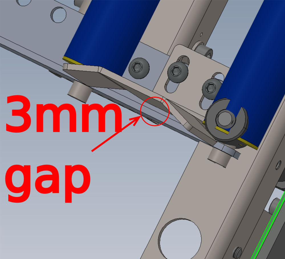
Étape 2 - Set position 1
Set backfence position 1 to have a gap of 3mm at the indicated point

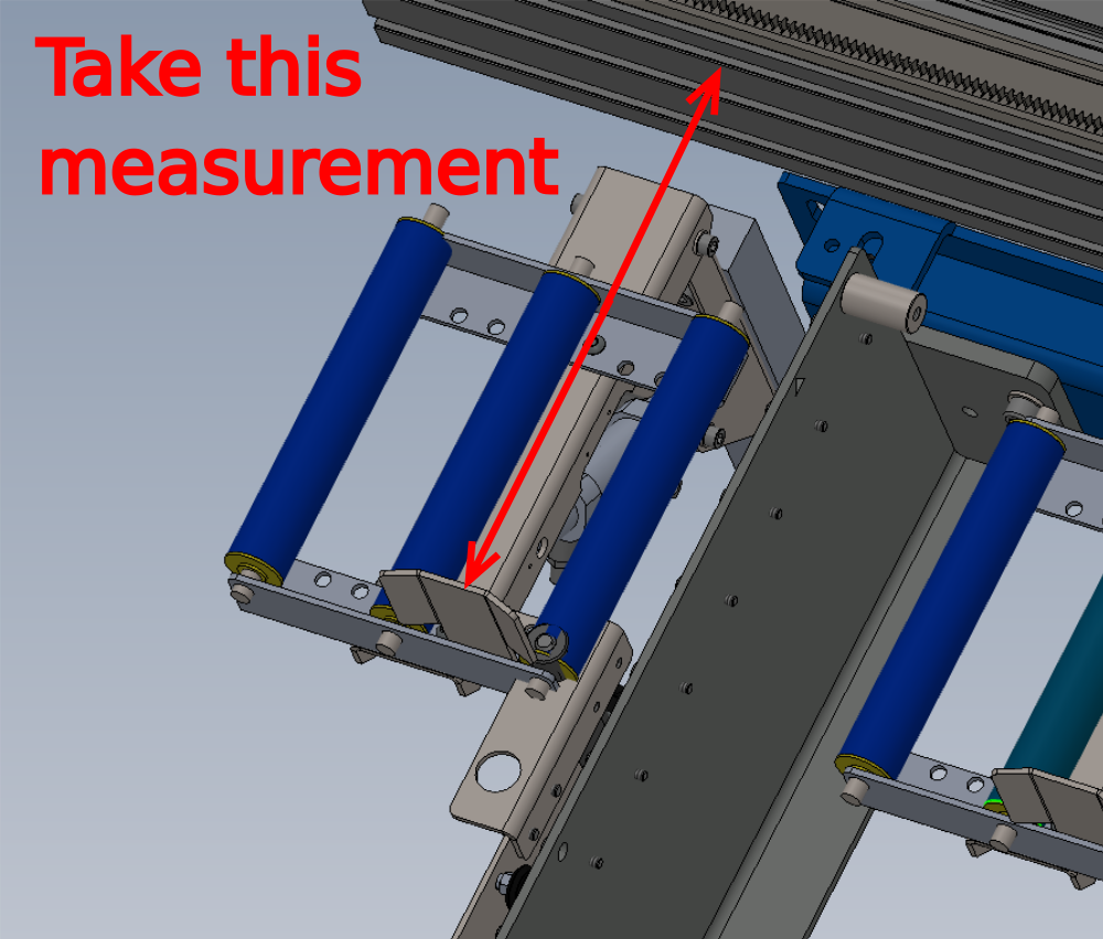
Étape 3 - Measure Position 1
Take measurement at indicated point
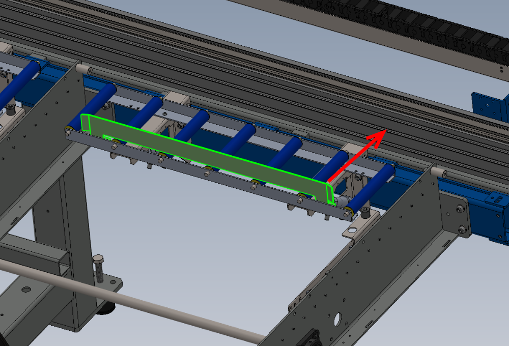
Étape 4 - Set position 10
Set position 10 to measure taken in previous step from position 1
Étape 5 - Add wire line to backfences
Fit wire line to backfences to span all

Étape 6 - Ensure only positions 1 and 10 are contacting
Ensure all positions of backfences except 1 and 10 are not touching wire line
Étape 7 - Adjust each backfence
Individually adjust each backfence to be less than 1mm from wireline but not touching
Étape 8 - Finalise alignment
The first 2 meter section of backfences from position 1 should now be fine tuned with a 2 meter straight edge
Position 2 meter straight edge against indicated points

Étape 9 - Quality /alignment check
Use steel rule to measure each backfence position from hepco rail
Measurement taken in step 3 should indicated at all backfences if set correctly .

Étape 10 - Gripper position setting
Gripper position requires setting now that back fences are aligned
The following steps should be followed for correct alignment

Étape 11 - Use setting jig
Ensure setting jig is set against position 1 backfences
Ensure setting jig is orientated correctly , correct offset of holes towards backfence
Draft
 Français
 English
 Deutsch
 Español
 Italiano
 Português