| [version en cours de rédaction] | [version en cours de rédaction] |
| Ligne 5 : | Ligne 5 : | ||
|Categories=Production | |Categories=Production | ||
|Difficulty=Hard | |Difficulty=Hard | ||
| − | |Duration= | + | |Duration=5 |
|Duration-type=hour(s) | |Duration-type=hour(s) | ||
}} | }} | ||
Version actuelle datée du 3 avril 2024 à 12:26
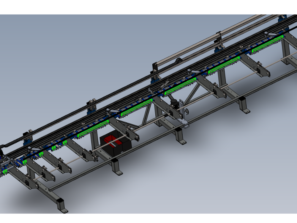
Procedure for correct alignment of module E back fences and channel bar

Difficulté
Difficile
Durée
5 heure(s)
Sommaire
- 1 Introduction
- 2 Étape 1 - Unless otherwise stated
- 3 Étape 2 - Quality check
- 4 Étape 3 - Set position 1
- 5 Étape 4 - Measure Position 1
- 6 Étape 5 - Set position 10
- 7 Étape 6 - Add wire line to backfences
- 8 Étape 7 - Ensure only positions 1 and 10 are contacting
- 9 Étape 8 - Adjust each backfence
- 10 Étape 9 - Finalise alignment
- 11 Étape 10 - Quality /alignment check
- 12 Étape 11 - Back fence height quality check
- 13 Étape 12 - Gripper position setting
- 14 Étape 13 - Use setting jig
- 15 Étape 14 - Adjust gripper
- 16 Étape 15 - Check all positions
- 17 Étape 16 - Finalise all fasteners
- 18 Étape 17 - Fit channel bars
- 19 Étape 18 - Set channel Bar position
- 20 Étape 19 - Position gripper
- 21 Étape 20 - Adjust each swivel assembly
- 22 Étape 21 - Adjust bump stop
- 23 Étape 22 - Set height of channel bar
- 24 Étape 23 - Check clearance
- 25 Étape 24 - Fastener check
- 26 Commentaires
Introduction
Tools Required
Standard hex key set
Standard spanner set
Wire Line setting equipment
600mm rule
Workshop Gripper setting jig
2 meter straight edge
Parts Required
Étape 1 - Unless otherwise stated
Use Loctite 243 on all fasteners
Use Loctite 572 on all threaded pneumatic connection
Pen mark all fasteners to show finalised

Étape 2 - Quality check
It is vital that the backfences are square to the rollers on the roller table assemblies.
If backfences are not square, varying readings will be encountered when setting back fence alignment
To check
Make sure backfence is secured to roller bed assembly
Use gripper setting jig and place on blue rollers, and push up to back fence
Backfence should be touching jig at top and bottom point. If not, back fence can be manipulated by hand to ensure it sits in a square position in relation gto the setting jig.
This check MUST be done before backfence alignment

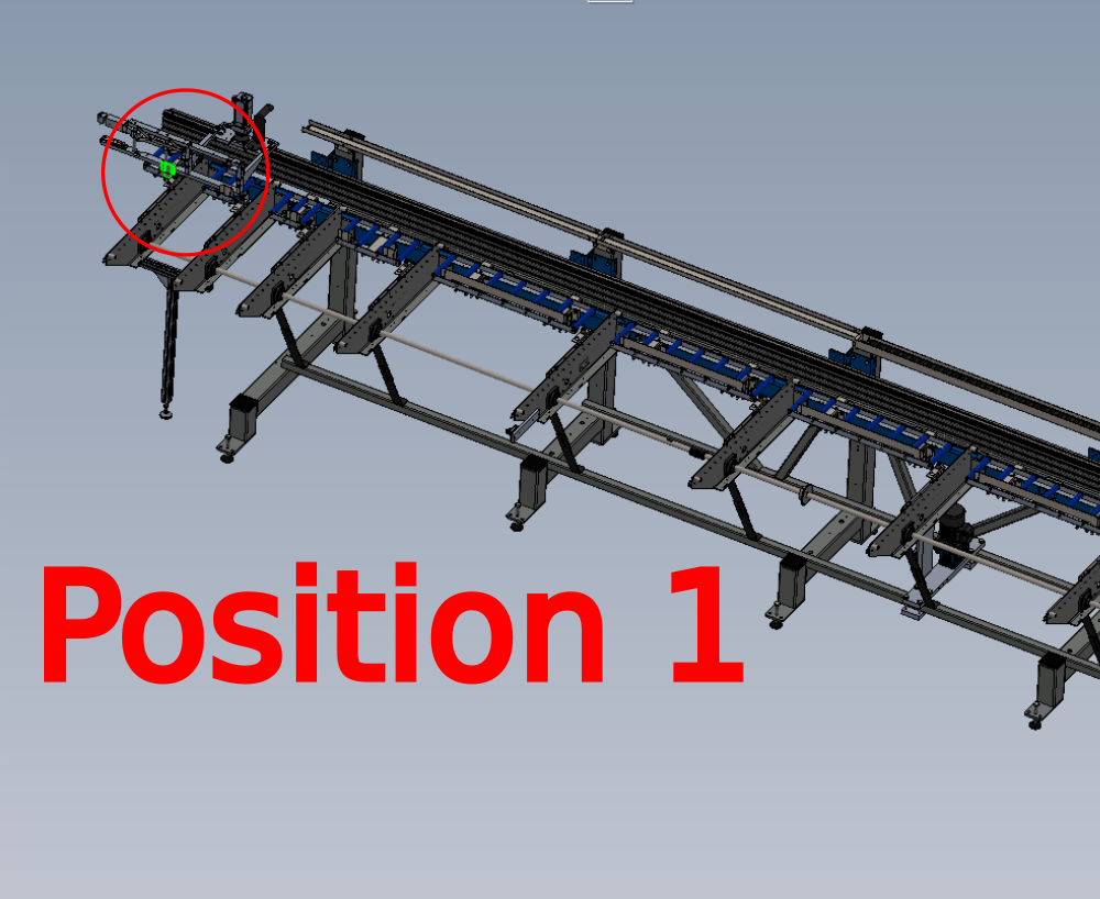
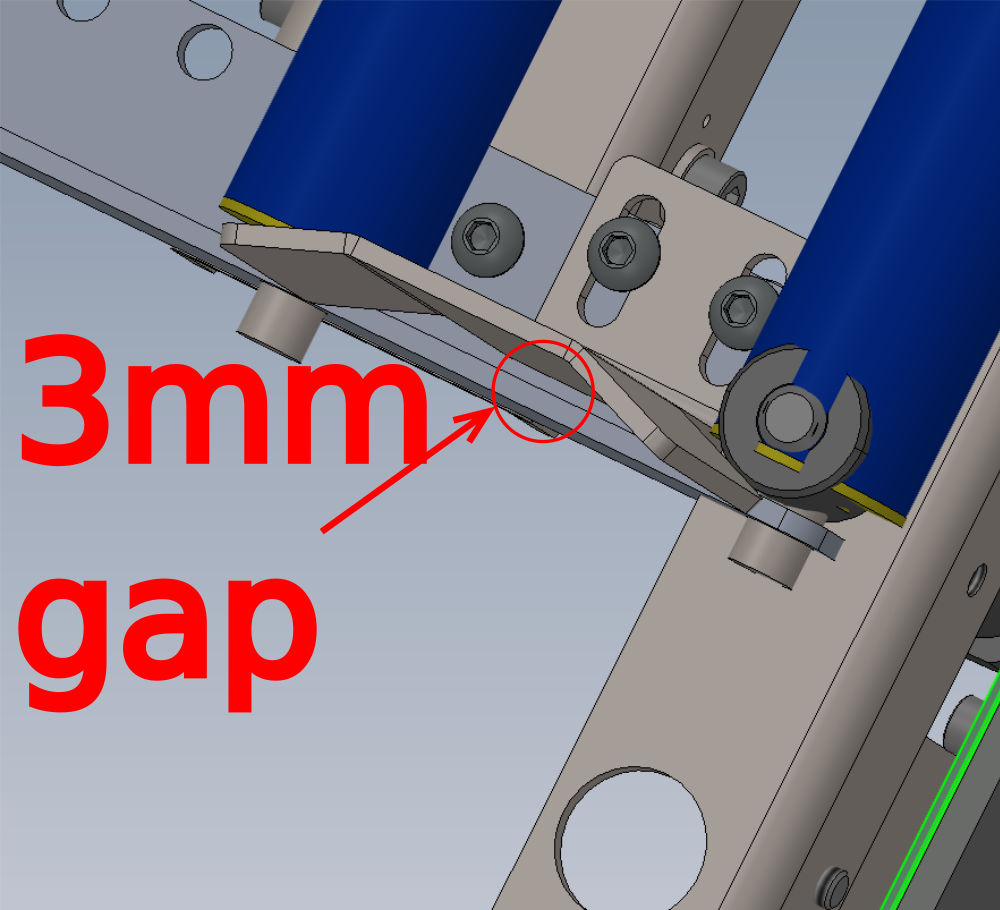
Étape 3 - Set position 1
Set backfence position 1 to have a gap of 3mm at the indicated point

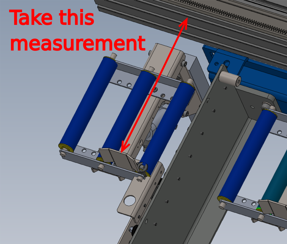
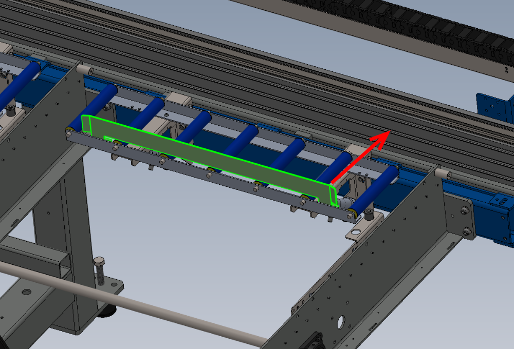
Étape 4 - Measure Position 1
Take measurement at indicated point
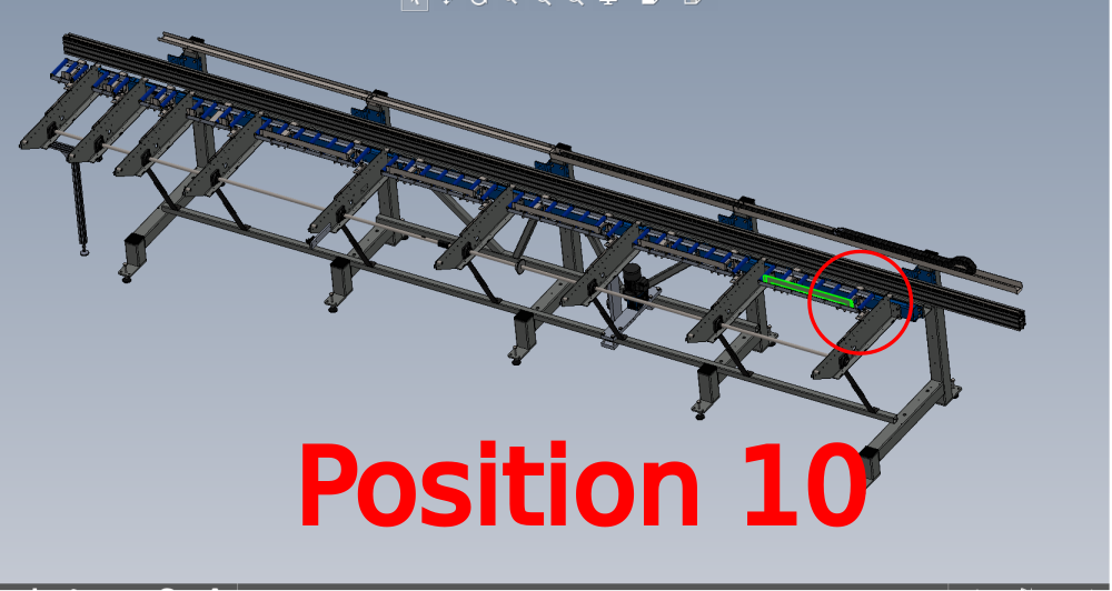
Étape 5 - Set position 10
Set position 10 to measure taken in previous step from position 1
Tolerance -+ 0.5mm
Étape 6 - Add wire line to backfences
Fit wire line to backfences to span all

Étape 7 - Ensure only positions 1 and 10 are contacting
Ensure all positions of backfences except 1 and 10 are not touching wire line
Étape 8 - Adjust each backfence
Individually adjust each backfence to be less than 0.5mm from wireline but not touching
Étape 9 - Finalise alignment
The first 2 meter section of backfences from position 1 should now be fine tuned with a 2 meter straight edge
Position 2 meter straight edge against indicated points

Étape 10 - Quality /alignment check
Use steel rule to measure each backfence position from hepco rail
Measurement taken in step 3 should indicated at all backfences if set correctly .
Tolerance -+ 0.5mm

Étape 11 - Back fence height quality check
Backfence height needs to be checked in the roller lowered position.
To do this
1 Remove air from cylinders to allow rollers to drop
2 Use 2 meter straight edge to span between transfer arms
3 drag straight edge over backfences, straight edge should not touch backfence at any point
4 Check this on all roller beds on module E
Étape 12 - Gripper position setting
Gripper position requires setting now that back fences are aligned
The following steps should be followed for correct alignment

Étape 13 - Use setting jig
Ensure setting jig is set against position 1 backfences
Ensure setting jig is orientated correctly , correct offset of holes towards backfence
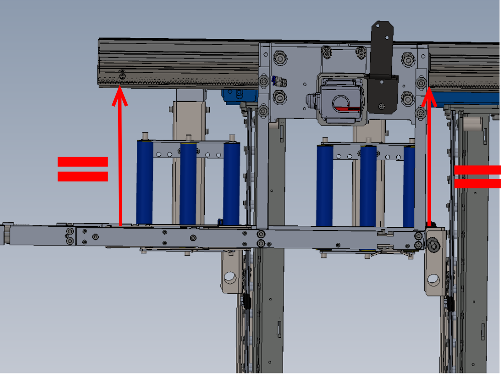
Étape 14 - Adjust gripper
Adjust gripper on mounting arms to align gripper teeth with setting jig
Ensure that when adjusting , gripper remains parallel to hepco beam . Check this by measuring the indicated points

Étape 15 - Check all positions
Once gripper position is set at position 1, it should be checked at all backfences for consistency
Report any discrepancy to supervisor
Étape 16 - Finalise all fasteners
Double check all fasteners used for adjustment have loctite 243, final tension applied and pen marked
Supervisor sign off required at this stage
Étape 17 - Fit channel bars
Fit Black take up pads D0008288 and D0015742 using ?what? fasteners

Étape 18 - Set channel Bar position
Channel bar positions now need to be set relative to new gripper position

Étape 19 - Position gripper
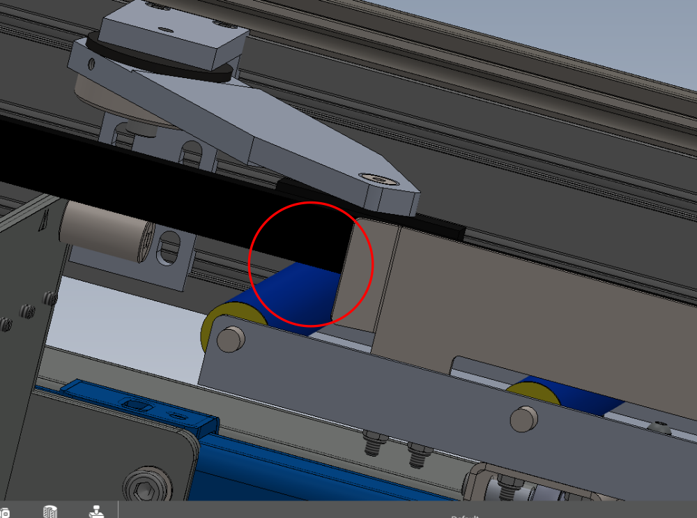
Position gripper in front cylinder assembly for channel bar
Adjust base of cylinder so that there is a 3mm gap present between gripper and channel bar, when cylinder is fully extended


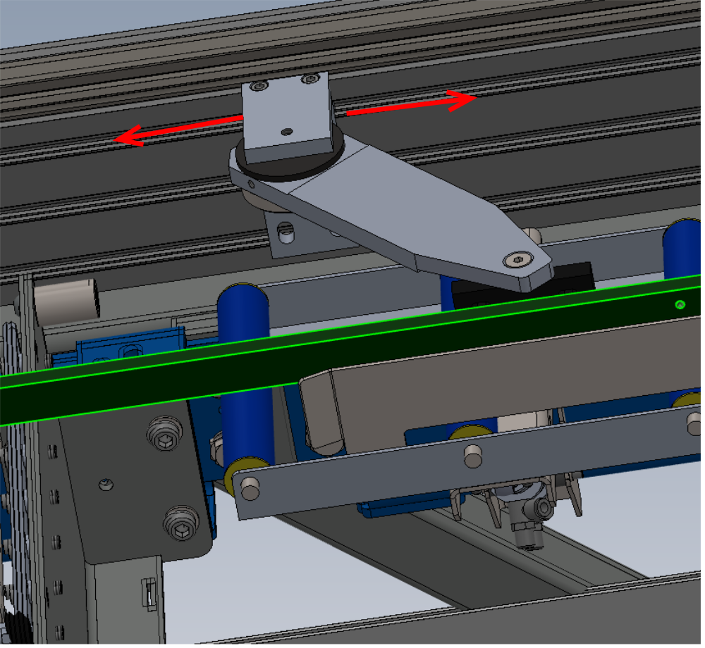
Étape 20 - Adjust each swivel assembly
Move gripper to each swivel assembly and adjust base to ensure 3mm gap when cylinder is fully extended
Repeat setting process for all swivel arms ( 4 off in total )
Étape 21 - Adjust bump stop
Adjust bump stop so it makes correctly when cylinder is retracted

Étape 22 - Set height of channel bar
Channel bar should be checked at all swivel points for the correct height setting
Adjust height of assemblies to set indicated height to 3-4mm
Ensure all measurements are consistent at adjustable points
Étape 23 - Check clearance
Fully extend channel cylinder
Move gripper along entire axis
3mm gap between channel bar and gripper should remain consistent at all points
Supervisor sign off required at this point
Étape 24 - Fastener check
Check that all fasteners are correctly tensioned, have had Loctite 243 applied and are pen marked
Draft
 Français
 English
 Deutsch
 Español
 Italiano
 Português