| [version en cours de rédaction] | [version en cours de rédaction] |
| Ligne 37 : | Ligne 37 : | ||
P0001118 cylinder 50 x 700 rodless x 1 | P0001118 cylinder 50 x 700 rodless x 1 | ||
| − | P0001145 Fitting smc flow controller elbow 10-1/4 bsp</translate> | + | P0001145 Fitting smc flow controller elbow 10-1/4 bsp |
| + | |||
| + | F0000315 D nut M8 x 4</translate> | ||
}} | }} | ||
{{Materials}} | {{Materials}} | ||
| Ligne 114 : | Ligne 116 : | ||
{{Tuto Step | {{Tuto Step | ||
|Step_Title=<translate>Attach cylinder to beam,</translate> | |Step_Title=<translate>Attach cylinder to beam,</translate> | ||
| − | |Step_Content=<translate>1 Attach cylinder to beam using M8 x 25 socket caps and M8 D- nuts | + | |Step_Content=<translate>1 Attach cylinder to beam using M8 x 25 socket caps and 4 off F0000315 M8 D- nuts |
Version actuelle datée du 27 février 2024 à 16:06
Instructions to mount and set hepco drive beam cylinder assembly

Difficulté
Moyen
Durée
3 heure(s)
Sommaire
- 1 Introduction
- 2 Étape 1 - Unless otherwise stated
- 3 Étape 2 - Add dowels
- 4 Étape 3 - Assemble drive adapter
- 5 Étape 4 - Attach Air fittings to cylinder
- 6 Étape 5 - Fit mounting brackets
- 7 Étape 6 - Attach mounting angles
- 8 Étape 7 - Fit cylinder assembly to frame
- 9 Étape 8 - Check hepco position
- 10 Étape 9 - Position cylinder stroke
- 11 Étape 10 - Attach cylinder to beam,
- 12 Étape 11 - Attach second cylinder mounting bracket
- 13 Étape 12 - Check Movement
- 14 Étape 13 - Finalise fasteners
- 15 Étape 14 - Add hard stops and dampers
- 16 Étape 15 - Set cylinder stroke hard stops
- 17 Étape 16 - Set damper position
- 18 Étape 17 - Quality check
- 19 Étape 18 - Attach sensors and brackets
- 20 Étape 19 - Fit cover
- 21 Commentaires
Introduction
Tools Required
Standard hex key set
Ball pein hammer
Standard spanner set
Parts Required
D0015074 Cylinder Support x 2
D0015075 Cylinder Bracket x 4
D0015077B Cylinder Drive Adapter x 1
D0015144 Datum Switch Bracket x 2
D0015948 ZX5 Beam Move Cylinder Guard x 1
E0000336 Sensor: M8; 2mm, PNP N/O, M8 conn x 2
P0000109 RB Series Shock Absorber x 2
P0001118 cylinder 50 x 700 rodless x 1
P0001145 Fitting smc flow controller elbow 10-1/4 bsp
F0000315 D nut M8 x 4Étape 1 - Unless otherwise stated
All bolts to have Loctite 243 adhesive applied unless otherwise stated
All Threaded Pneumatic connections to have Loctite 570 applied
All bolts to be pen marked once adhesive applied and correct tension added

Étape 2 - Add dowels
Add 4 off 8mm x 24mm dowels to parts D0015708 as shown

Étape 3 - Assemble drive adapter
Assemble D0015077b with contains D0015707 x 1 and D0015708 x 2 using M8 x 30 socket caps 4 off


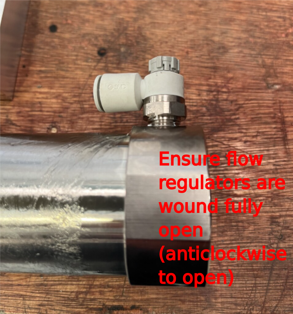
Étape 4 - Attach Air fittings to cylinder
Fit 2 off P0001145 air fittings to cylinder P0001118

Étape 5 - Fit mounting brackets
1 Mount D0015074 2 off brackets using 8 off M8 x 50 socket caps and M8 a form washers , orientating cylinder as shown
2 Mount D0015077 to cylinder using 4 off M8 x 30 socket caps

Étape 6 - Attach mounting angles
Attach 4 off D0015075 to frame using M8 x 25 bolts and Heavy M8 washers as shown
Do not apply adhesive


Étape 7 - Fit cylinder assembly to frame
Lightly attach cylinder assembly to frame , orientated as shown. Use 16 off M8 x 25 socket caps with heavy M8 washers
Do not apply adhesive


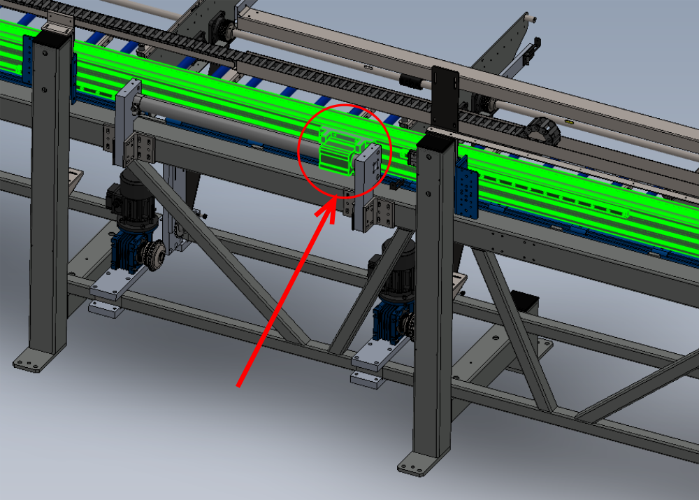
Étape 8 - Check hepco position
Ensure hepco rail is still at correct datum position of 895mm

Étape 9 - Position cylinder stroke
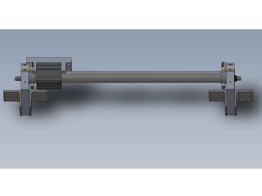
Check that cylinder is positioned as shown
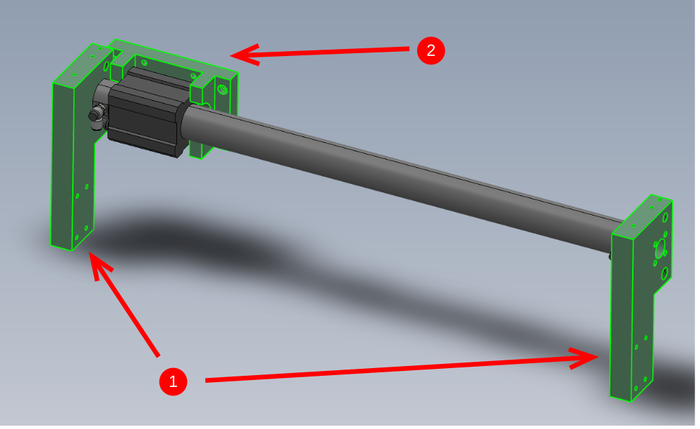
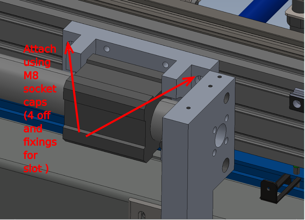
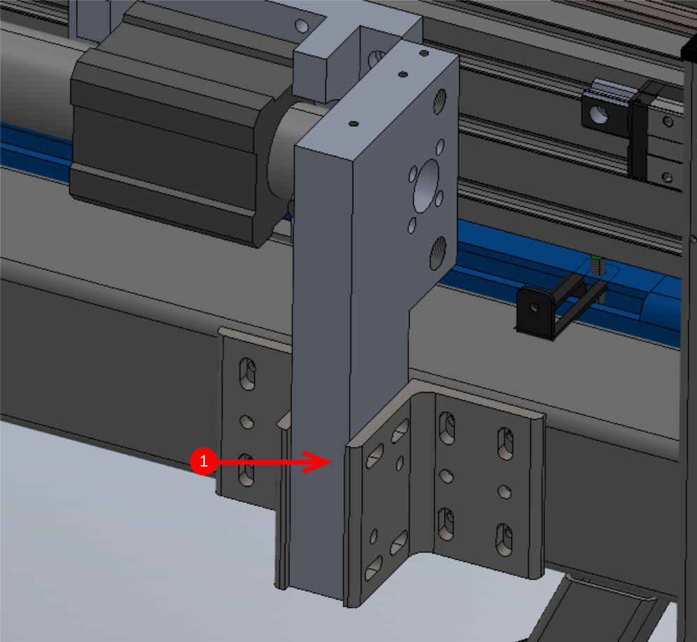
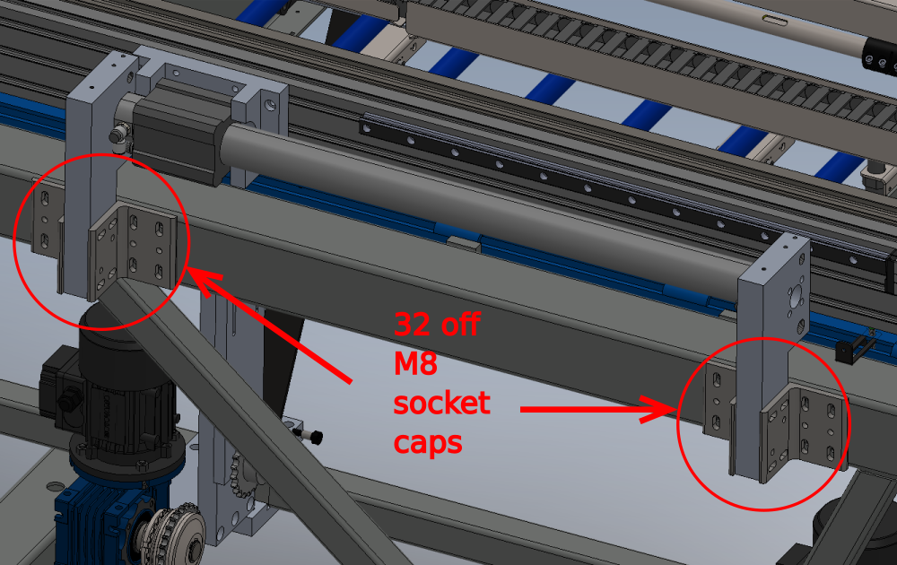
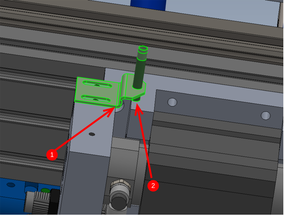
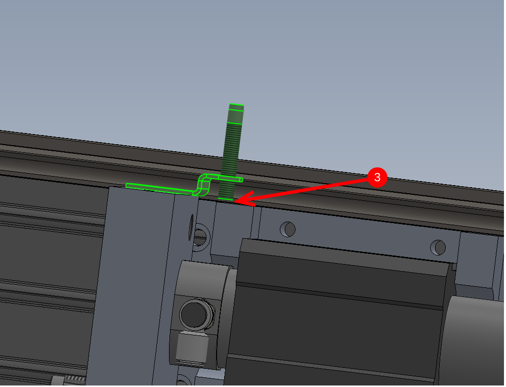
Étape 10 - Attach cylinder to beam,
1 Attach cylinder to beam using M8 x 25 socket caps and 4 off F0000315 M8 D- nuts
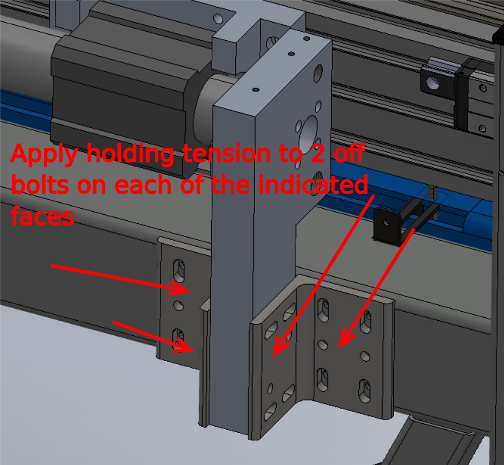
2 Tension bolts to hold indicated bracket in a vertical position
3 Apply holding tension to these fasteners 1 and 2
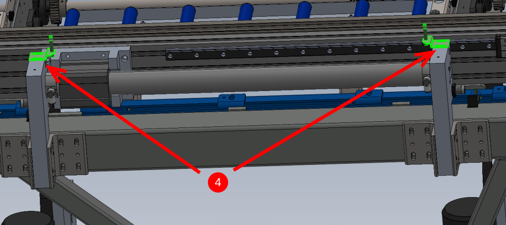
Étape 11 - Attach second cylinder mounting bracket
1 Move hepco beam to extended position as shown
2 Apply holding tension to same bolts as other mounting bracket
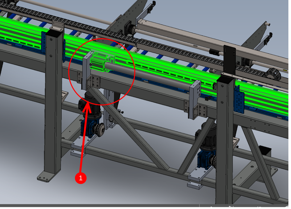
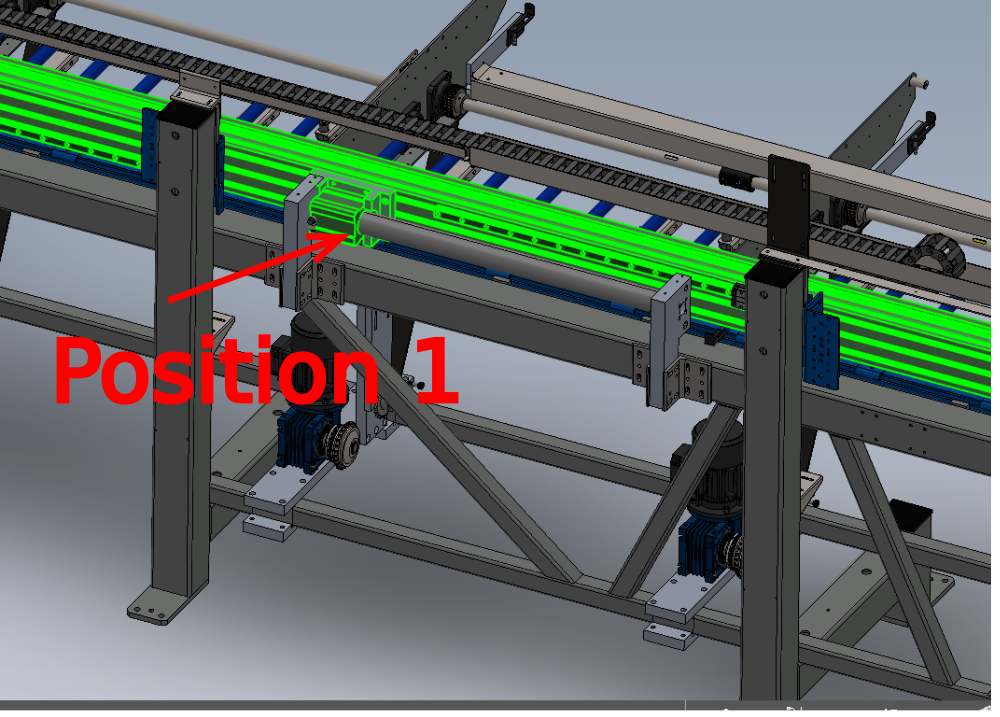
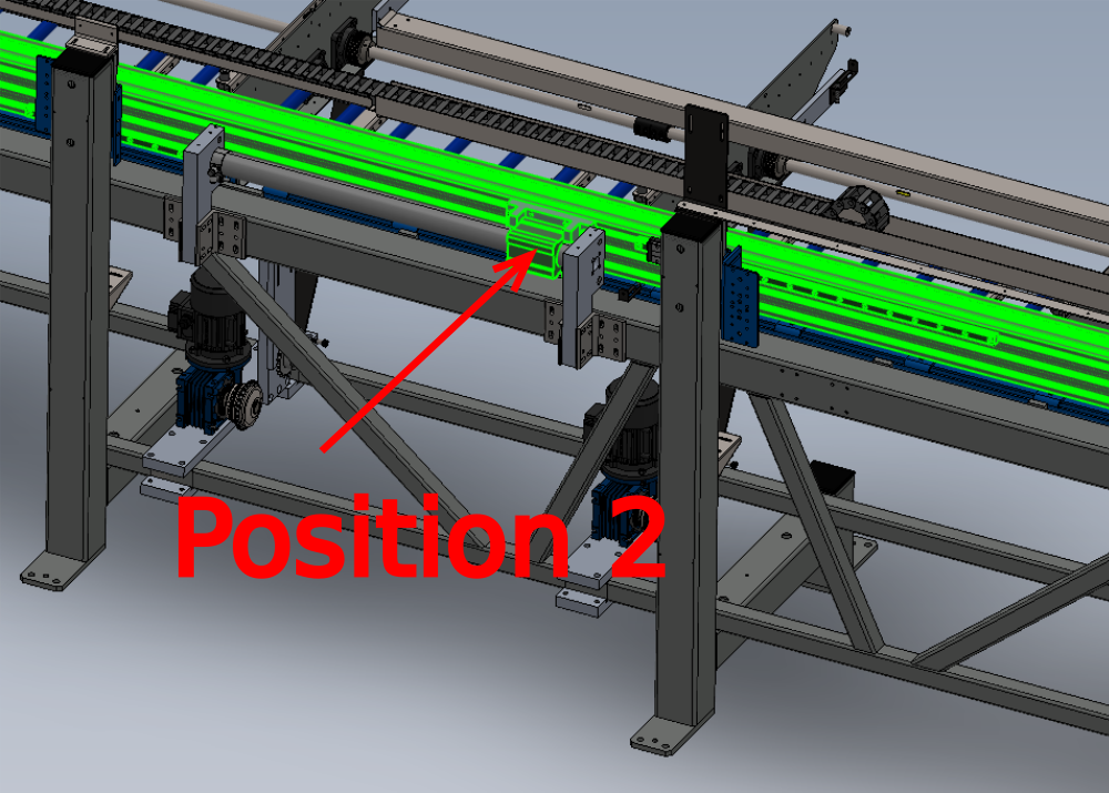
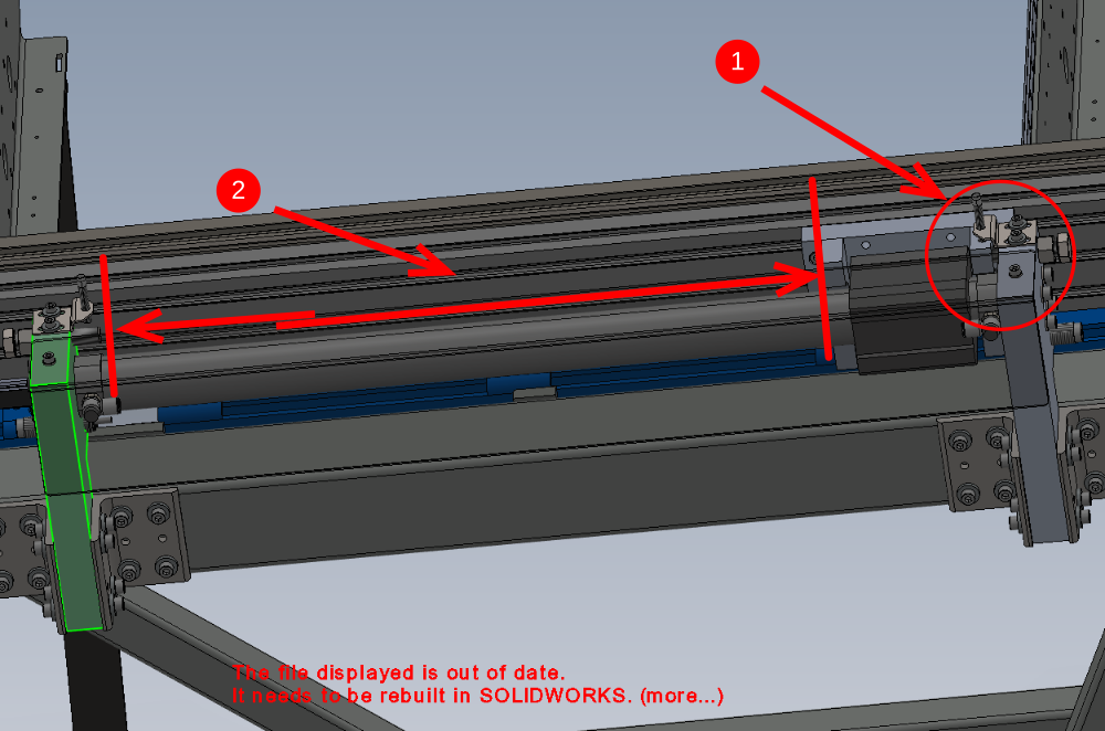
Étape 12 - Check Movement
Quality check movement of beam from position 1 to 2
Movement must be free and consistent over the entire stroke of the cylinder
1 If not alignment must be rechecked by adjusting mounting brackets to obtain smooth running
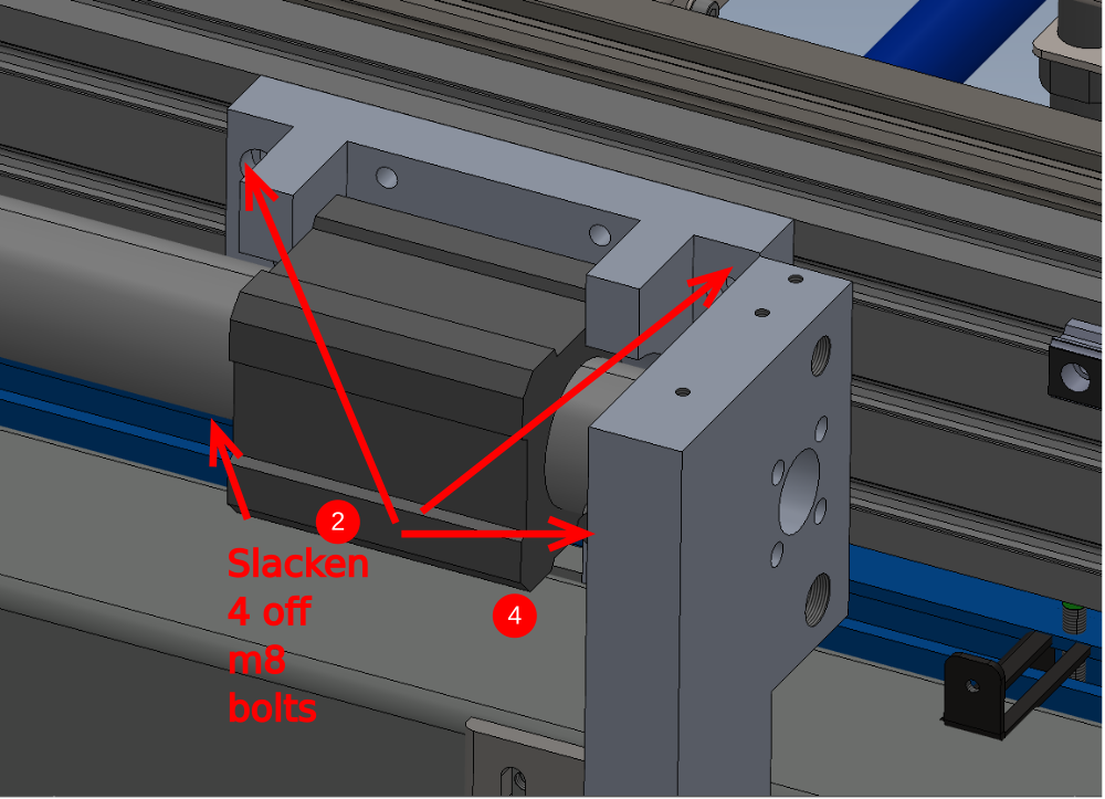
2 Once Movement is free running , secondary check alignment by removing tension of fasteners holding cylinder mount block to hepco beam
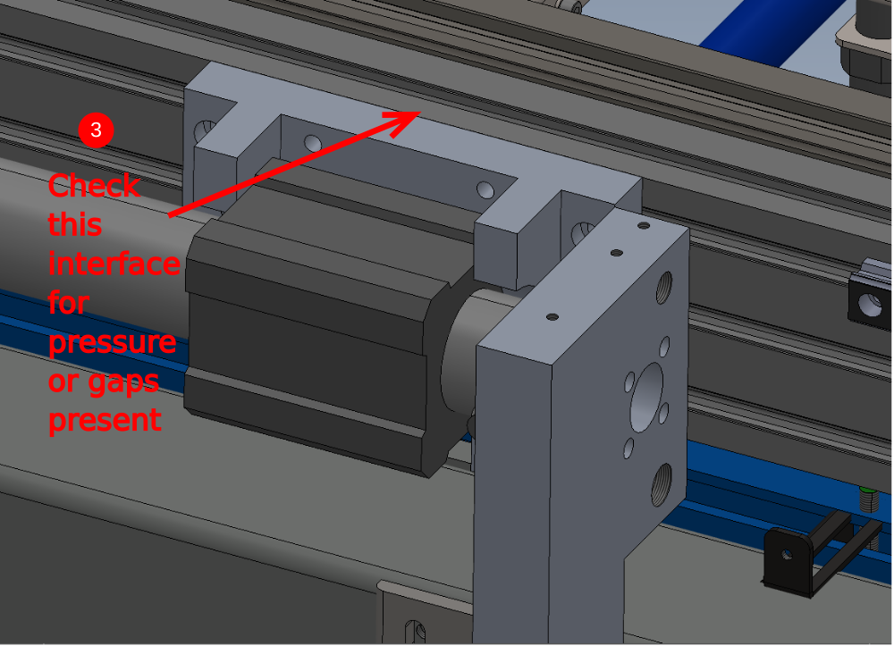
3 Check that slight movement is possible between the hepco rail and the mounting block. Block should not move away from hepco rail when un fastened or be held against under pressure. If either of these happen it indicates mis alignment between components , and step 1 should be repeated
4 Tension m8 socket caps and apply final tension

Étape 13 - Finalise fasteners
Once alignment has been achieved, 32 off M8 socket caps will need to be individually removed , adhesive applied and finalised .
Étape 14 - Add hard stops and dampers
1 off of each per side
1 Use 2 off M16 x 80 set bolts and standard M16 nuts
2 P0000109 damper x 2
Do not fully wind in either parts
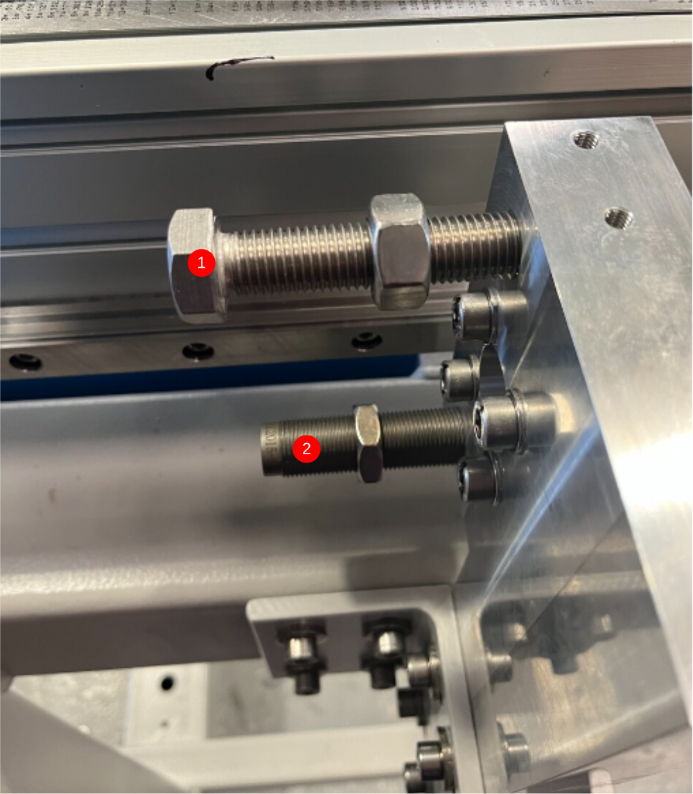
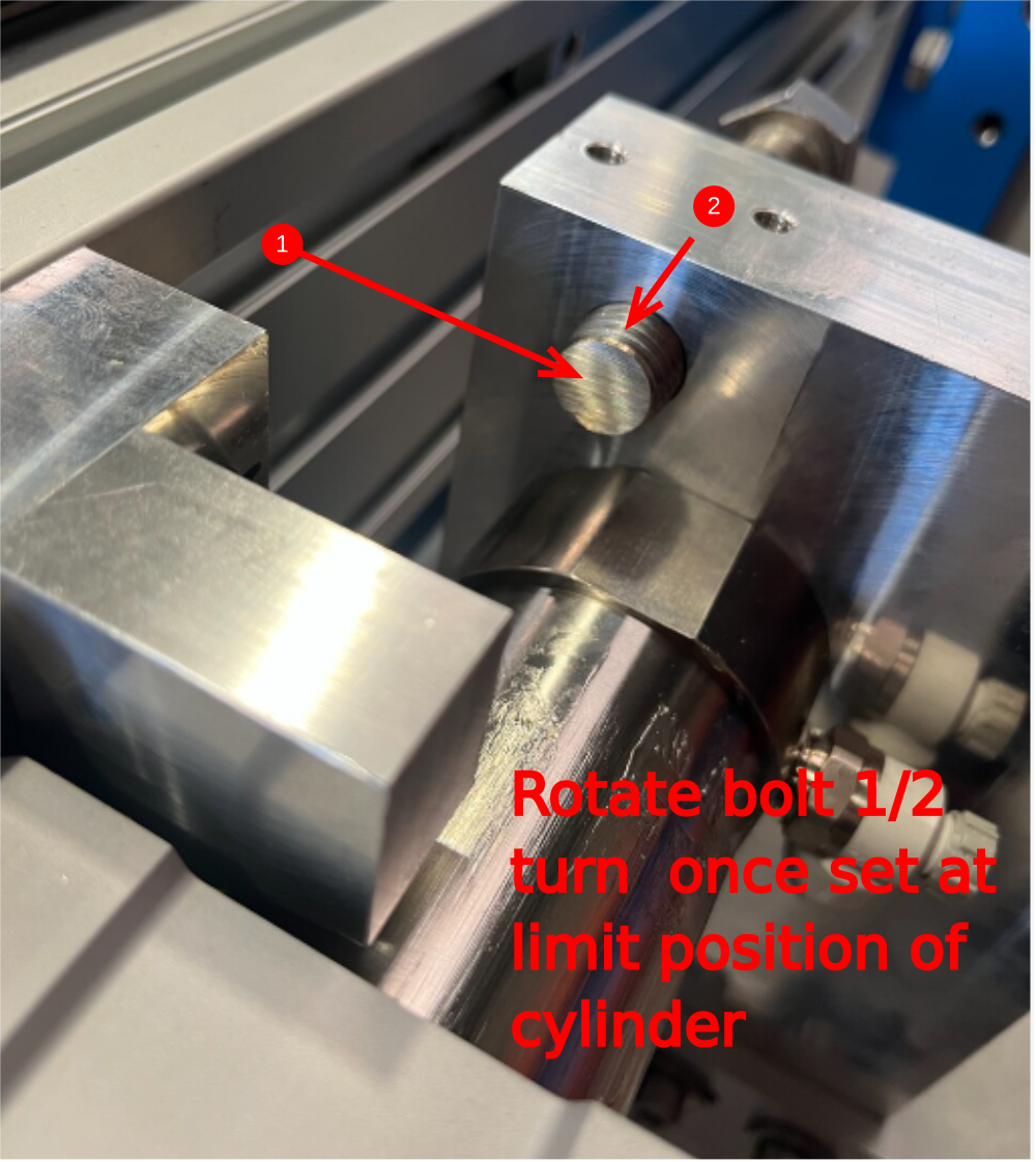
Étape 15 - Set cylinder stroke hard stops
Move beam to full cylinder extension in one direction.
1 Linisher flat end of set bolt and adjust M16 set bolt to touch face of cylinder mount when in this fully extended position
2 Move beam away from bolt and rotate an EXACT 3/4 turn clockwise at the hex head to set stop position and lock off with m16 nut
3 Repeat for opposite end set bolt, moving cylinder stroke to the opposite end of travel
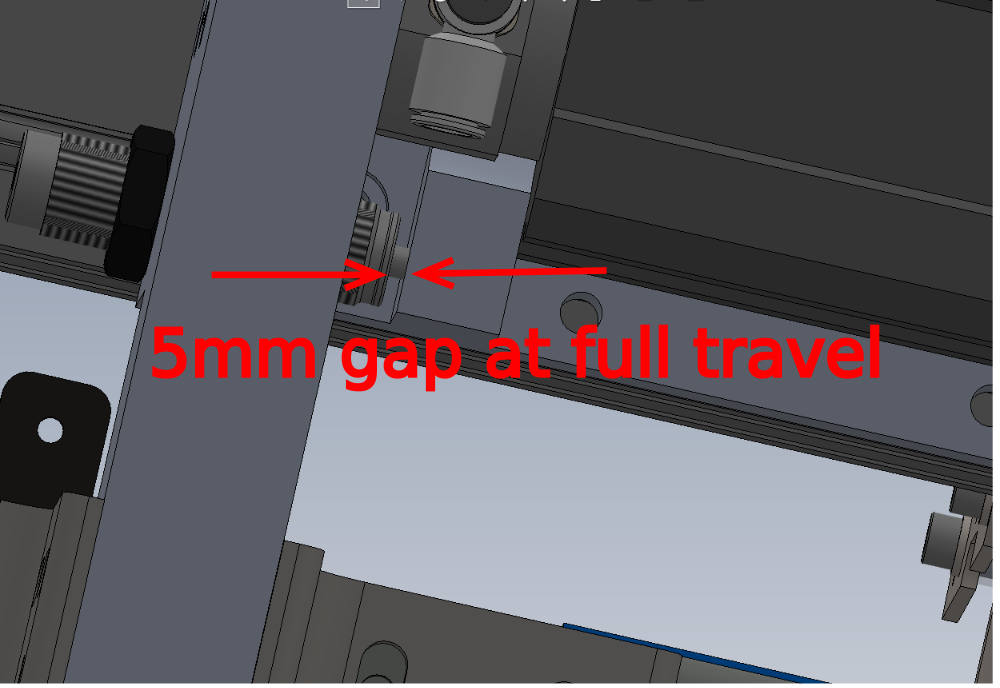
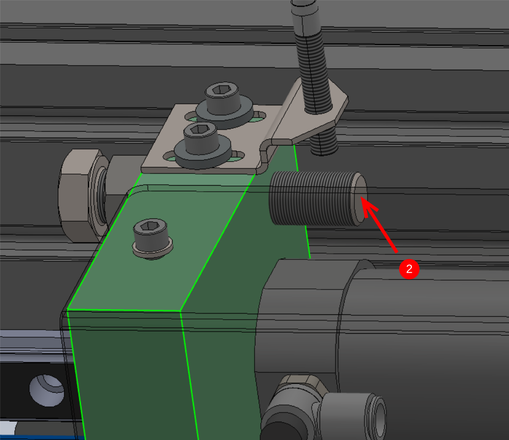
Étape 16 - Set damper position
Set damper position by moving cylinder to full stroke, and adjusting damper so a gap of 5mm is left at the indicated point
Lock off damper lock nut
Repeat for both sides
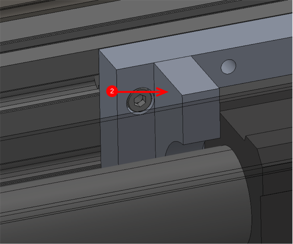
Étape 17 - Quality check
To check correct setting of stroke length, a measurement should be taken to confirm. To do this do the following steps.
1 Move cylinder to one position against set hard stop
2 Measure between Hex bolt thread end and cylinder anchor as shown
3 Confirm measurement is between the range of 696-698mm. Any measurement outside of this tolerance requires resetting of hard stops correctly
Étape 18 - Attach sensors and brackets
1 Mount sensor brackets D0015144 with M6 x 16 socket caps x 2 and heavy M6 washers
2 Fit E0000336 sensor and Adjust bracket using slots to set sensor to edge of block when at full travel
3 Ensure sensor is set as close as possible to reading face
4 Repeat for other side
Étape 19 - Fit cover
once all above steps have been followed, Guard D0015948 can be fitted
Pics and fastener sizes required
Draft
 Français
 English
 Deutsch
 Español
 Italiano
 Português