Alignment of loading arm assembly

Difficulté
Moyen
Durée
8 heure(s)
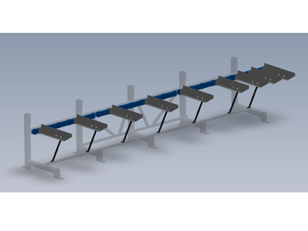
Introduction
procedure for correct alignment of mounting sections to main frame, and relative setting of load arms
parts required
D0015038B 1 off
D0015039B 1 off
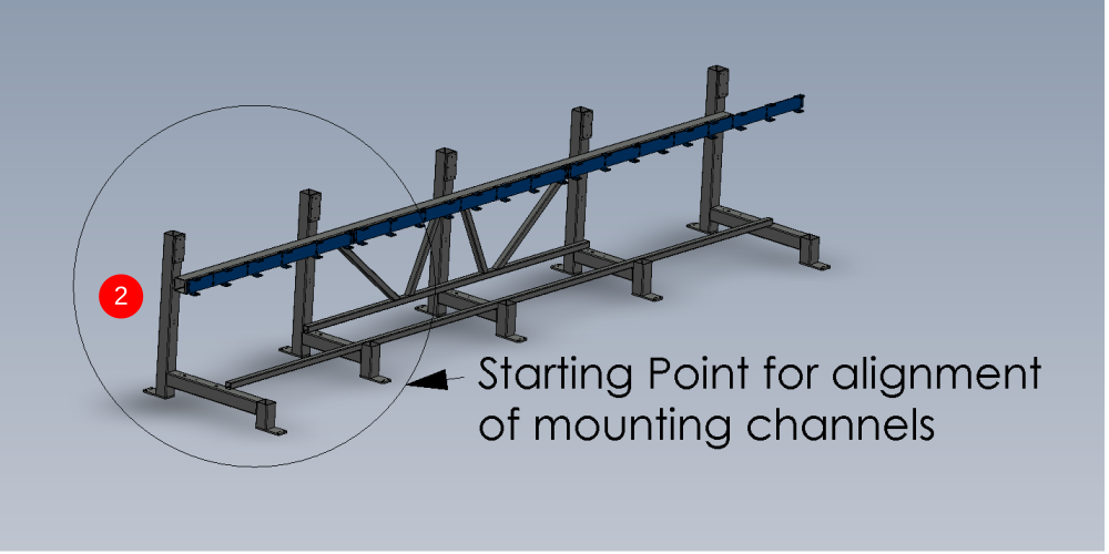
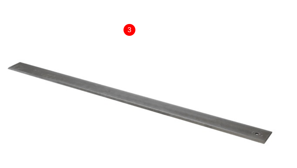
D0015257 1 offÉtape 1 - Fitting of Mounting Channel 3
1 Fit mounting channels to frame using m12 Set bolts and A form washers.Do not add adhesive to bolts at this stage . Do not tension bolts.
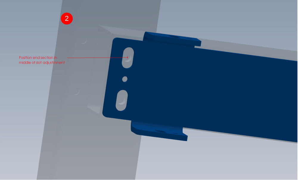
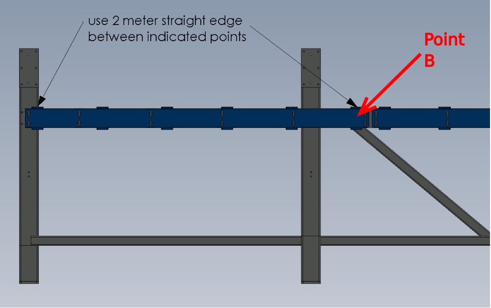
2 Set the first mounting channel to the middle of the adjustment slot at the extreme end of the frame
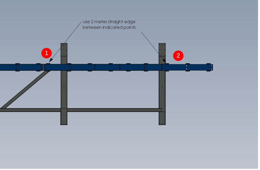
3 Place 2 meter straight edge between indicated points , and raise or lower point b to bring straight edge level with engineers level
4 Tighten bolts to hold in place

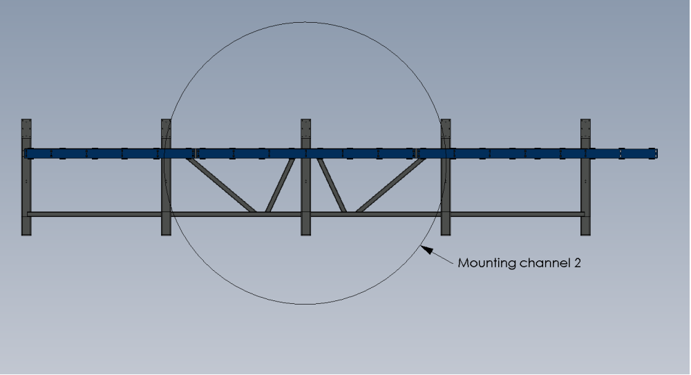
Étape 2 - Fitting of Mounting channel 2
1 Move channel 2 section up or down to copy height of adjacent channel 3. Use the tabs as the reference points
2 Use 2 meter straight edge and level between points indicated
Move channel 2 at the end indicated, to give a level reading
3 Tighten bolts to hold in place
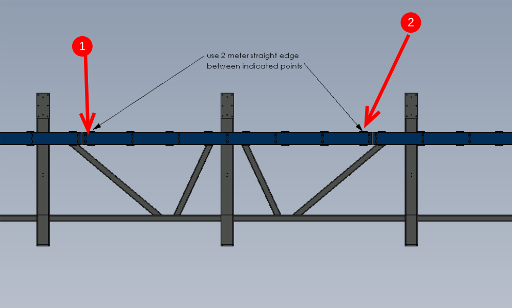
Étape 3 - Fitting of mounting channel 1
1 Move channel 1 section up or down to copy height of adjacent channel 2. Use the tabs as the reference points
2 Use 2 meter straight edge and level between points indicated
Move channel 1 at the end indicated, to give a level reading
3 Tighten bolts to hold in place

Étape 4 - Quality Check Required
Once at this stage with mounting channels being set in position, a quality check is required from a Supervisor.

Étape 5 - Finalising Fixings
1 Remove Set bolt
2 Add adhesive Loctite 243 to bolt.
3 Refit and tighten
4 Mark head with ink to show completion of fixing
5 Repeat for all M12 fixings holding on mounting sections 1,2 and 3

Étape 6 - Dowel in Position
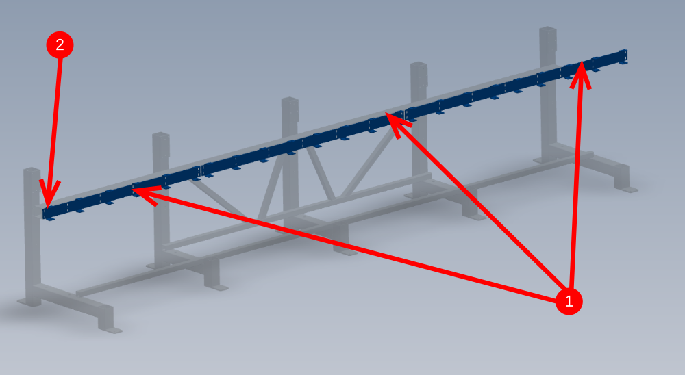
1 Drill 8mm Diameter holes in all roll pin holes situated between previous tightened m12 bolts ( 19 off in total reference detail 1 )
2 Insert 8mm x 24mm spiral pins to 8mm holes
3 Clean drilled areas of swarf and cutting fluid

Draft
 Français
 English
 Deutsch
 Español
 Italiano
 Português