| [version en cours de rédaction] | [version en cours de rédaction] |
| Ligne 55 : | Ligne 55 : | ||
All bolts to be pen marked once adhesive applied and correct tension added</translate> | All bolts to be pen marked once adhesive applied and correct tension added</translate> | ||
|Step_Picture_00=R0015086_Assemble_Pneumatics_on_to_electrical_cabinet_loctite_243.png | |Step_Picture_00=R0015086_Assemble_Pneumatics_on_to_electrical_cabinet_loctite_243.png | ||
| + | }} | ||
| + | {{Tuto Step | ||
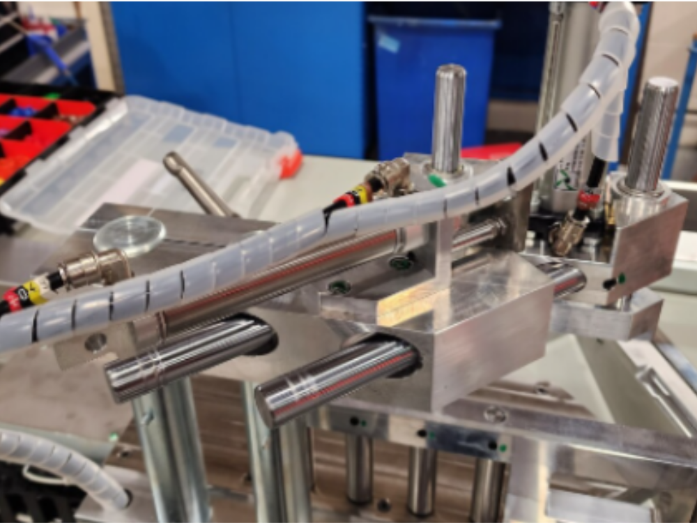
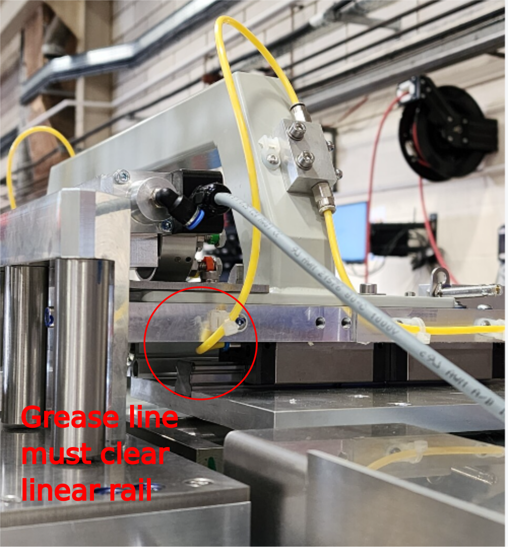
| + | |Step_Title=<translate>SY saddle grease lines</translate> | ||
| + | |Step_Content=<translate>Ensure clearance is present between linear rail and grease line as indicated | ||
| + | |||
| + | |||
| + | Ensure no tight bends are implemented when fitting</translate> | ||
| + | |Step_Picture_00=R0015146_Pneumatic_pipe_Installation_Part_3_Screenshot_2024-02-27_120734.png | ||
| + | |Step_Picture_01=R0015146_Pneumatic_pipe_Installation_Part_3_Screenshot_2024-02-27_120743.png | ||
| + | |Step_Picture_01_annotation={"version":"2.4.6","objects":[{"type":"image","version":"2.4.6","originX":"left","originY":"top","left":0,"top":0,"width":500,"height":539,"fill":"rgb(0,0,0)","stroke":null,"strokeWidth":0,"strokeDashArray":null,"strokeLineCap":"butt","strokeDashOffset":0,"strokeLineJoin":"miter","strokeMiterLimit":4,"scaleX":1.2,"scaleY":1.2,"angle":0,"flipX":false,"flipY":false,"opacity":1,"shadow":null,"visible":true,"clipTo":null,"backgroundColor":"","fillRule":"nonzero","paintFirst":"fill","globalCompositeOperation":"source-over","transformMatrix":null,"skewX":0,"skewY":0,"crossOrigin":"","cropX":0,"cropY":0,"src":"https://stuga.dokit.app/images/6/6a/R0015146_Pneumatic_pipe_Installation_Part_3_Screenshot_2024-02-27_120743.png","filters":[]},{"type":"wfellipse","version":"2.4.6","originX":"center","originY":"center","left":236.95,"top":406.05,"width":132.71,"height":132.71,"fill":"rgba(255,0,0,0)","stroke":"#FF0000","strokeWidth":2,"strokeDashArray":null,"strokeLineCap":"butt","strokeDashOffset":0,"strokeLineJoin":"miter","strokeMiterLimit":4,"scaleX":1,"scaleY":1,"angle":0,"flipX":false,"flipY":false,"opacity":1,"shadow":null,"visible":true,"clipTo":null,"backgroundColor":"","fillRule":"nonzero","paintFirst":"fill","globalCompositeOperation":"source-over","transformMatrix":null,"skewX":0,"skewY":0,"rx":66.35374004918899,"ry":66.35374004918899},{"type":"textbox","version":"2.4.6","originX":"center","originY":"center","left":131.5,"top":516.09,"width":129.88,"height":101.25,"fill":"#FF0000","stroke":"#FF0000","strokeWidth":1,"strokeDashArray":null,"strokeLineCap":"butt","strokeDashOffset":0,"strokeLineJoin":"miter","strokeMiterLimit":4,"scaleX":1.65,"scaleY":1.65,"angle":0,"flipX":false,"flipY":false,"opacity":1,"shadow":null,"visible":true,"clipTo":null,"backgroundColor":"","fillRule":"nonzero","paintFirst":"fill","globalCompositeOperation":"source-over","transformMatrix":null,"skewX":0,"skewY":0,"text":"\nGrease line must clear linear rail ","fontSize":20,"fontWeight":"normal","fontFamily":"sans-serif","fontStyle":"normal","lineHeight":1.16,"underline":false,"overline":false,"linethrough":false,"textAlign":"left","textBackgroundColor":"","charSpacing":0,"minWidth":20,"styles":{} }],"height":647,"width":600} | ||
| + | |Step_Picture_02=R0015146_Pneumatic_pipe_Installation_Part_3_Screenshot_2024-02-27_120750.png | ||
| + | |Step_Picture_03=R0015146_Pneumatic_pipe_Installation_Part_3_Screenshot_2024-02-27_120758.png | ||
}} | }} | ||
{{Tuto Step | {{Tuto Step | ||
Version actuelle datée du 27 février 2024 à 14:20
Details to install pneumatic and electrical loom

Difficulté
Difficile
Durée
1 minute(s)
Sommaire
- 1 Introduction
- 2 Étape 1 - Unless otherwise stated
- 3 Étape 2 - SY saddle grease lines
- 4 Étape 3 - Y214 Z Turret Infeed
- 5 Étape 4 - Y215 Z Turret Outfeed
- 6 Étape 5 - Y224 Outfeed Z block
- 7 Étape 6 - Loom cables through saddle brace
- 8 Étape 7 - Finalise SY control loom
- 9 Étape 8 - Finalise SY stepper motor loom
- 10 Étape 9 - Check Movement and loom position
- 11 Étape 10 - Ethercat Stepper control box
- 12 Étape 11 - Lower trunking
- 13 Étape 12 - SR connections
- 14 Étape 13 - Finalise looms
- 15 Étape 14 - Rear loom
- 16 Étape 15 - Additonal pipes
- 17 Étape 16 - Connect Flow regulators And 8mm blue pipe
- 18 Étape 17 - Connect Y80 High/low pressure system
- 19 Étape 18 - Connect valve bank 1 and 2
- 20 Étape 19 - Fit trunking lids to finalise
- 21 Commentaires
Introduction
This instruction is to incorporate assembly R0015033B Module F Wiring loom alongside this
See Electrical department for prepared components from above assembly
Tools Required
Pipe cutters
Pipe identification markers
Flush cutters
Parts Required
P0000010 6mm 1/8 elbow fitting x 6 P0000046 Fitting: 'Y' Adaptor 6mm x 6
P0000047 Bulkhead Elbow 6mm x 1
P0000159 Fitting: Stem Blanking Plug 6mm x 2
P0000160 Fitting: Flow Controller In Line 6mm x 2
P0000551 6mm inline Quick Exhaust Fitting x 3
P0001030 Fitting: SMC 6mm Equal Tee x 1
P0001008 regulator x 3
P0001009 Regulator nut x 3
P0001106 Plug in reducer 12-8mm x 1
P0001107 Fitting 12mm equal tee x 1
P0001166 12mm tube to tube elbow x 1Étape 1 - Unless otherwise stated
All bolts to have Loctite 243 adhesive applied unless otherwise stated
All Threaded Pneumatic connections to have Loctite 570 applied
All bolts to be pen marked once adhesive applied and correct tension added

Étape 2 - SY saddle grease lines
Ensure clearance is present between linear rail and grease line as indicated
Ensure no tight bends are implemented when fitting


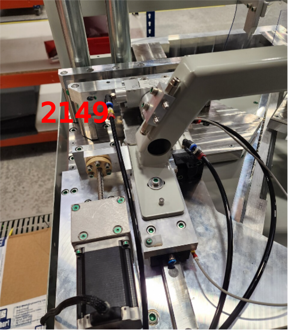
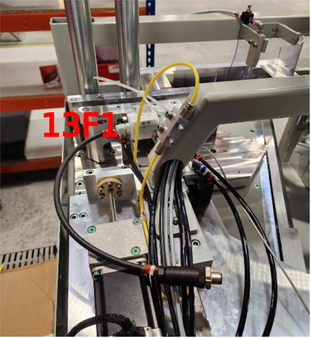
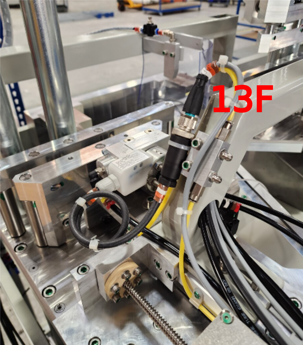
Étape 3 - Y214 Z Turret Infeed
1 Cut 1 off 6mm black pipe at 5 meter and add identification of 2149
2 Use cable 13F1 and 13F from cable loom box
3 Attach pipe and cable as shown
4 Loom additional cable 13F as shown
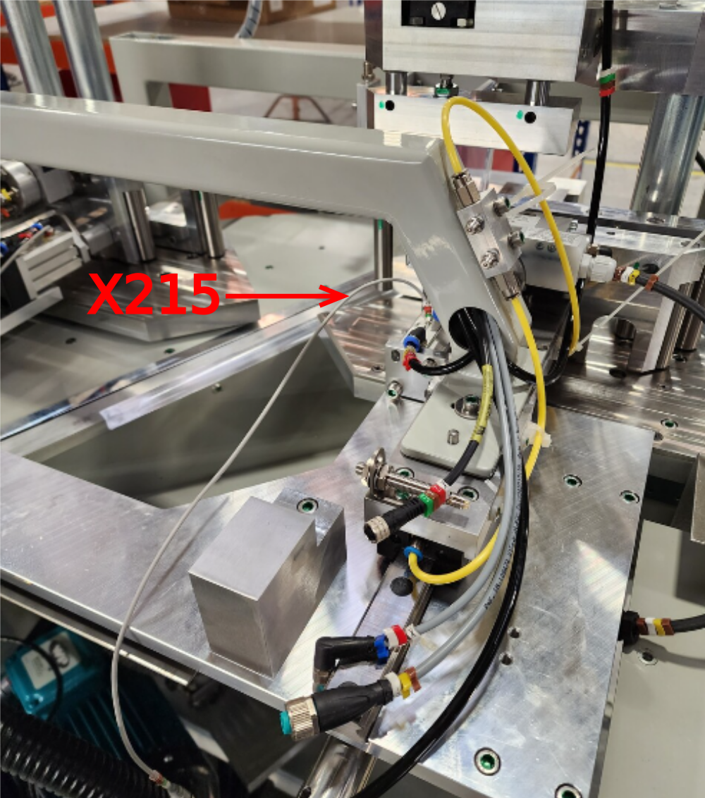
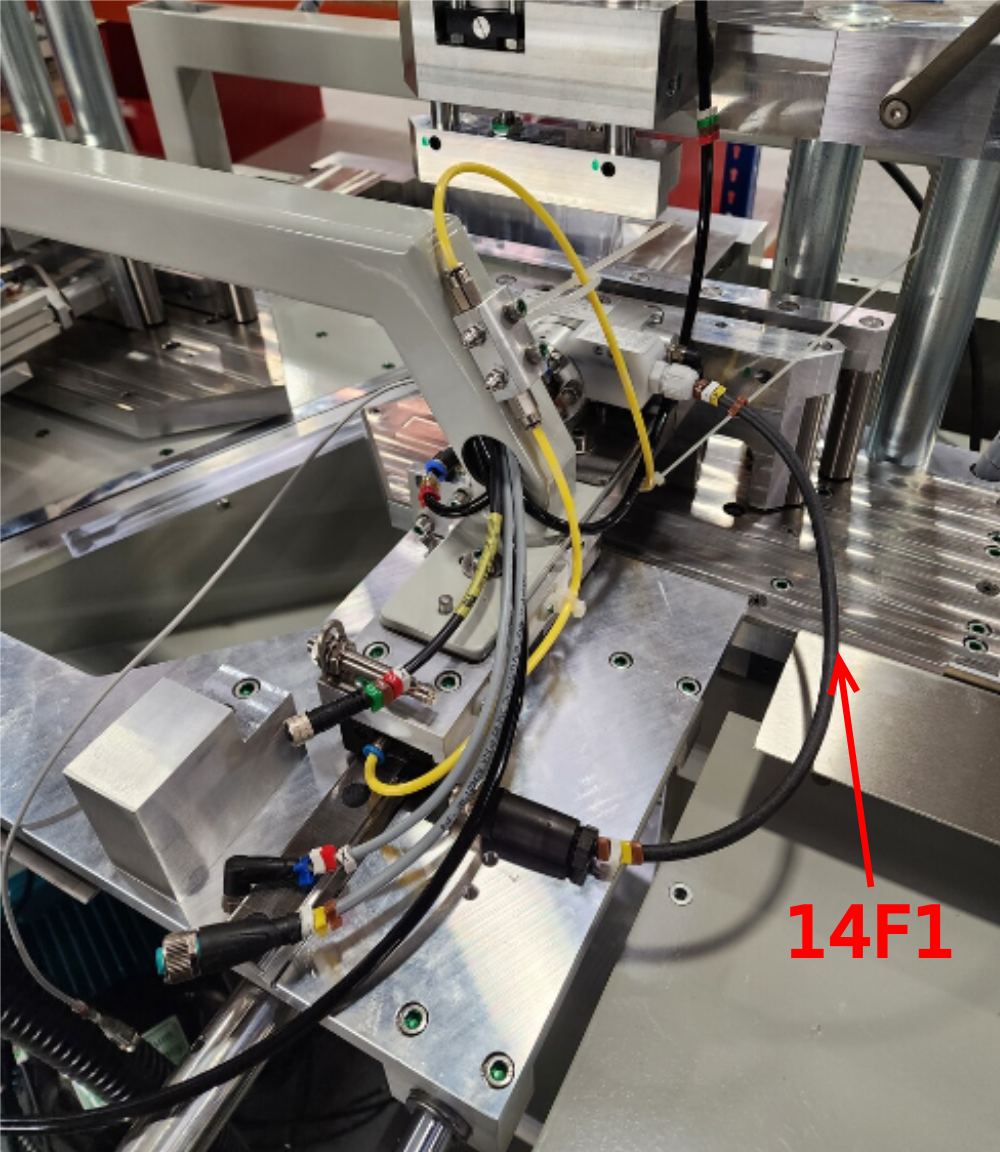
Étape 4 - Y215 Z Turret Outfeed
1 Cut 1 off 6mm black pipe at 5.5 meters and identify as 2159 and fit to turret
2 Use cable 14F1 and fit to turret
3 Fit extension cable 14F to 14F1
Étape 5 - Y224 Outfeed Z block
1 Cut 2 off 6mm black pipes at 5.5 meters and label as 2241 and 2249
2 Use reed switch cable X215, X215 extension cable
2 Use reed switch cable X215, X215 extension cable
3 Fit X215 reed switch to cylinder. Use test box to set position on switch. Set to home position as shown. (cylinder retracted is home position )
Étape 6 - Loom cables through saddle brace
1 Use cable X296 from wiring loom box. Leave right angle end at outfeed side . Run through saddle brace along with X215,14F and 3 off 6mm pipes 2249,2241 and 2159. Cables to exit saddle brace other end
2 Loom and tidy as shown . Exactly replicate loom


Étape 7 - Finalise SY control loom
1 Bring looms together as shown . Exactly replicate
2 Use spiral wrap to complete loom
3 Use cable tie base to secure loom . Ensure loom length is correct for full range of table movement, and as short as possible
4 Add pre wired cable 40f with interlock as shown ( will require removing from prebuilt top hood if fitted )
5 Integrate into loom from saw motor


Étape 8 - Finalise SY stepper motor loom
Add pre made cables CB17f and CB18F to stepper motor and loom as shown with spiral wrap. Secure with tie wrap to tie wrap base, again ensuring loom length is correct for full travel but as short as possible
Add spiral wrap to switch cable


Étape 9 - Check Movement and loom position
Quality check that cable and pipe looms do not hinder operation of SY axis table
Movement should be free and no cable pinch or trapping should be possible
check no excessive tension is put on looms or stepper motor connections

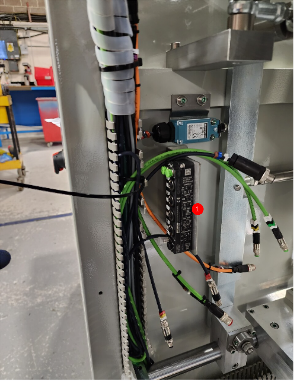
Étape 10 - Ethercat Stepper control box
1 Use cables 16F, 23F and EC04F from wiring loom box
Leave tails as shown for connection along with cables CB17f and CB18F from previous loom , and EC05F and 24F from rear Ethercat.
2 Add trunking lid to finalise all cables and pipes within


Étape 11 - Lower trunking
1 Identify pipe 2139 from front loom, and add P0000160 flow regulator to the position shown
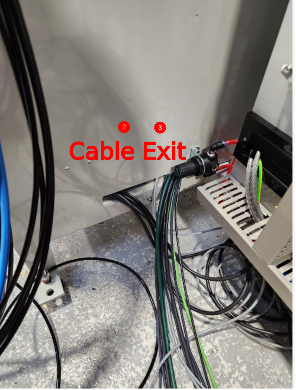
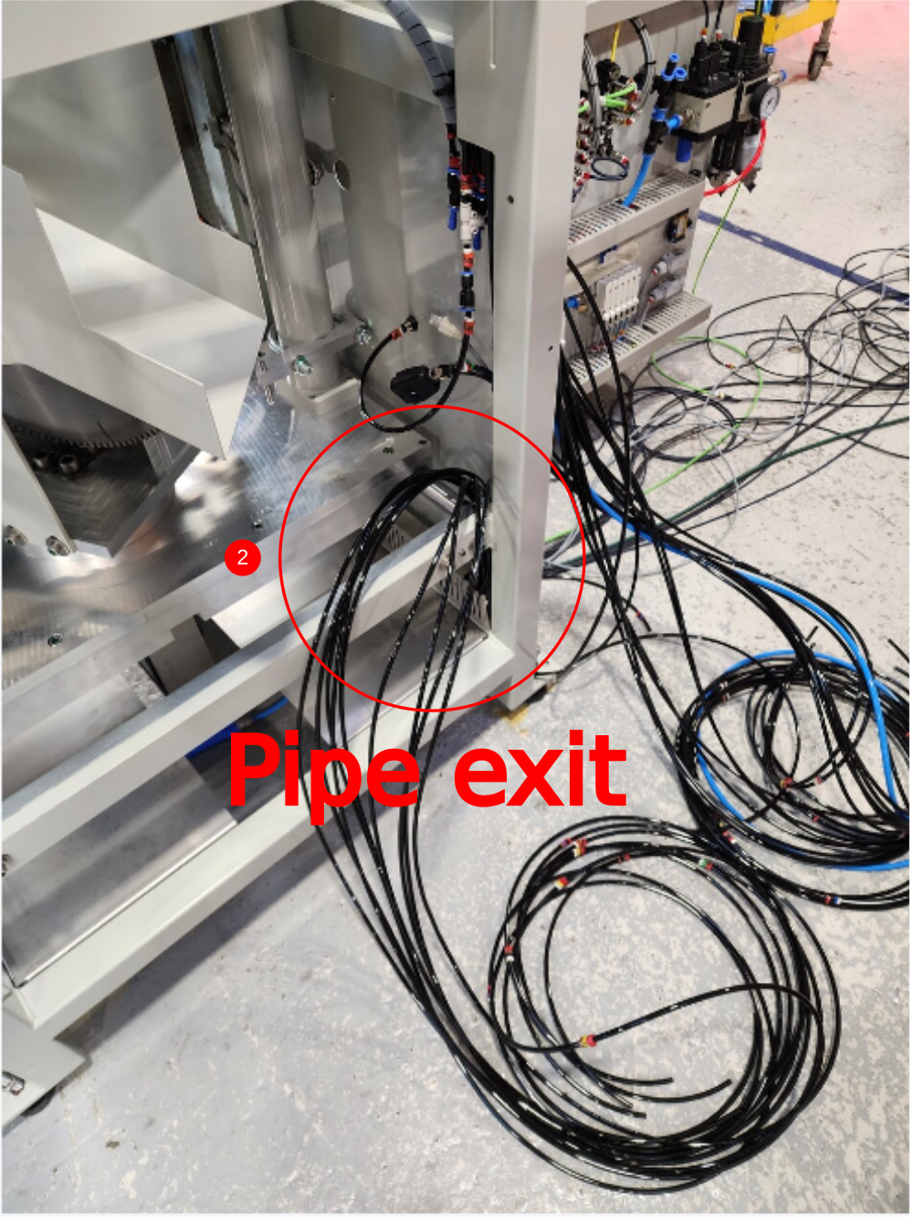
2 Insert Loom from front of machine into lower trunking, cable to exit slot midway along trunking , pipes to travel full length of trunking and exit rear
3 Insert cables from rear loom into lower trunking and exit from slot
Étape 12 - SR connections
Use cables CBX126 and CBSR1
Attach CBX126 to SR Axis datum as shown and run cable to lower section
Attach CBSR1 to servo and loom as shown into lower trunking with CBX126
Note to remove 1 off trunking upstand to allow cables to enter
Use slot to exit cables from trunking
Ensure loom allows for complete movement of bottom table


Étape 13 - Finalise looms
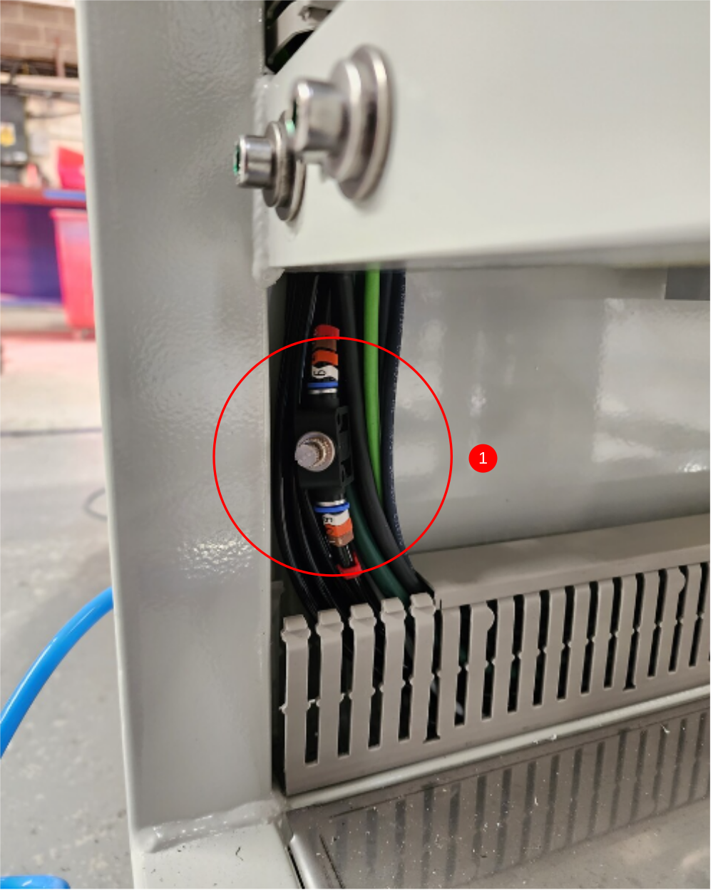
1 Exit remaining rear pipes at upper slot in panel
2 Tidy front and rear lower looms with cable ties
3 Fit lower trunking lid

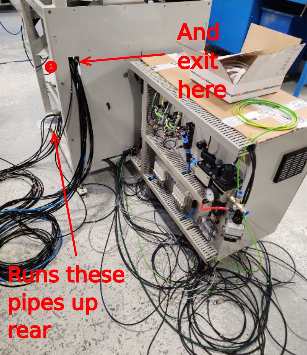


Étape 14 - Rear loom
Create Loom to run to electrical cabinet. Ensure pipes are not twisted and all pipes run parallel
Enter trunking as shown
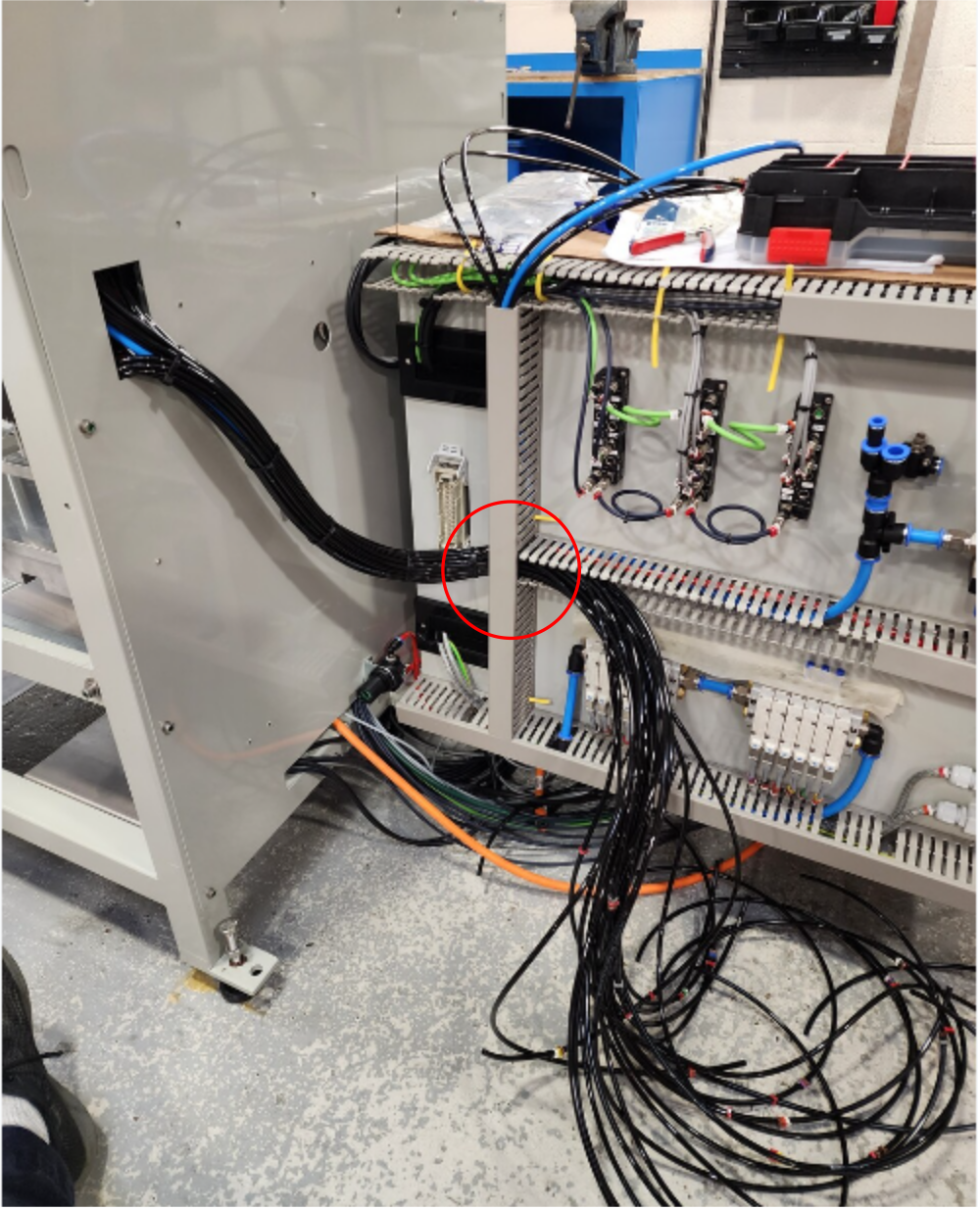

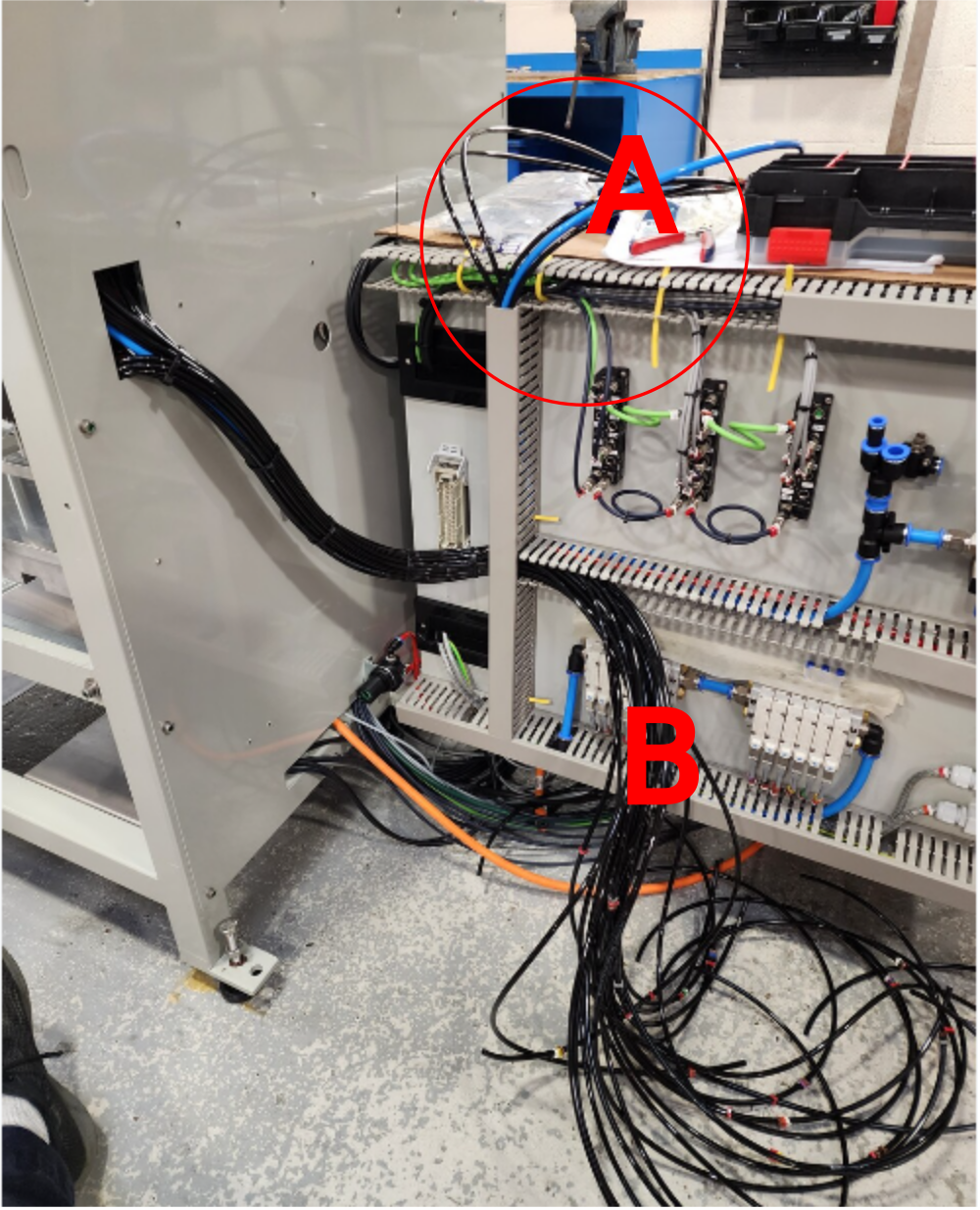
Étape 15 - Additonal pipes
From original loom divert pipes 2041 2 off and 2049 2 off and run to top of trunking
Also run 8mm blue from same loom
Cut and label 2 off 6mm black air pipes at 1.5meters and label 2041A and 2049A
Run these from point A to B as shown
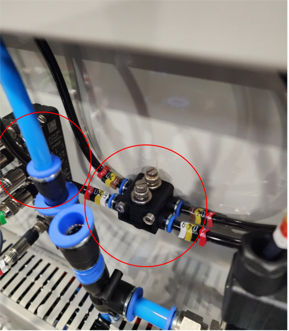
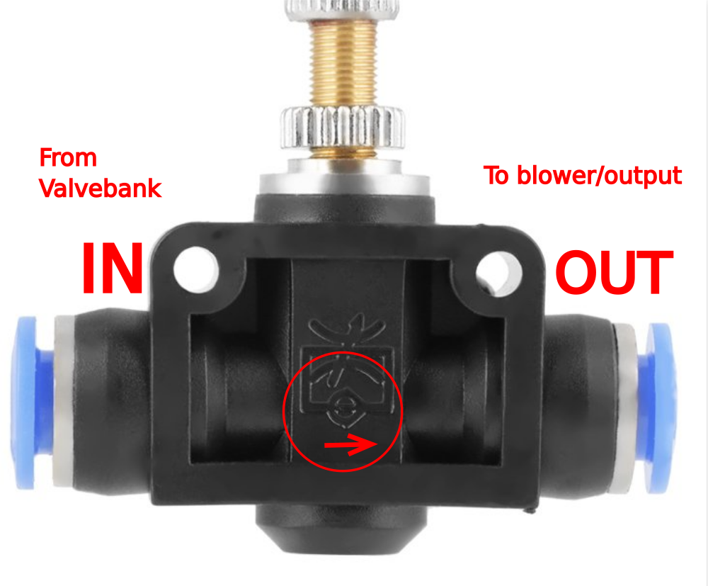
Étape 16 - Connect Flow regulators And 8mm blue pipe
Add 6mm Y connector to 2 off of each pipe to create single feed pipe . Connect 2041 and 2049 to OUT port on flow regulators
Connect 2041A and 2049A to IN port on flow regulators
Loom pipes neatly from trunking
Connect 8mm Blue air pipe to service unit as shown

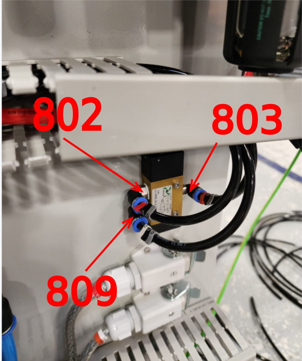
Étape 17 - Connect Y80 High/low pressure system
Add 6mm Y connector as shown to split 809 pipe from loom into 2 off 809 pipes
Connect 801 direct from loom into valve bank Y80 connection rear port
Connect 1 off 809 directly to valve bank at front
Identify Pipes 802 and 803 from loom
Run 802 803 and 809 out of the end of the trunking and connect to high/low pressure valve as shown


Étape 18 - Connect valve bank 1 and 2
Connect remaining pipes in loom to valve banks 1 and 2
Ensure cable marker Yxxx matches pipe number xxx
Ie Y204 labelled valve has 2041 and 2049 connections
Front port of valve bank will always have pipe numbers ending in 9 connected
Rear port of valve bank will always have pipe numbers ending in 1 connected


Étape 19 - Fit trunking lids to finalise
Fit trunking lids and finalise installation of pipe work
Ensure are looms are neat and tie wraps are appropriately used for retention

Draft
 Français
 English
 Deutsch
 Español
 Italiano
 Português