Details to install pneumatic and electrical loom

Difficulté
Difficile
Durée
1 minute(s)
Sommaire
- 1 Introduction
- 2 Étape 1 - Unless otherwise stated
- 3 Étape 2 - Important checks
- 4 Étape 3 - Y82 Outfeed top clamp Y204 Clamp position
- 5 Étape 4 - Y80 Infeed Top clamp and Y204 Clamp position
- 6 Étape 5 - Y80 Infeed Top clamp and Y204 Clamp position
- 7 Étape 6 - Y202 side clamp and Y206 centralise
- 8 Étape 7 - Front Cable Loom
- 9 Étape 8 - Y207 Saw cut conduit cables
- 10 Étape 9 - Y207 connection loom
- 11 Étape 10 - Y207 Cylinder connections
- 12 Étape 11 - Fit rear cables
- 13 Étape 12 - Fit rear hood connections
- 14 Étape 13 - Y213 Blower 1 and 2
- 15 Étape 14 - Fit small Spiral wrap
- 16 Étape 15 - Y210 Z Support and Y213 Blower
- 17 Commentaires
Introduction
This instruction is to incorporate assembly R0015033B Module F Wiring loom alongside this
See Electrical department for prepared components from above assembly
Tools Required
Pipe cutters
Pipe identification markers
Flush cutters
Parts Required
P0000010 6mm 1/8 elbow fitting x 6 P0000046 Fitting: 'Y' Adaptor 6mm x 6
P0000047 Bulkhead Elbow 6mm x 1
P0000159 Fitting: Stem Blanking Plug 6mm x 2
P0000160 Fitting: Flow Controller In Line 6mm x 2
P0000551 6mm inline Quick Exhaust Fitting x 3
P0001030 Fitting: SMC 6mm Equal Tee x 1
P0001008 regulator x 3
P0001009 Regulator nut x 3
P0001106 Plug in reducer 12-8mm x 1
P0001107 Fitting 12mm equal tee x 1
P0001166 12mm tube to tube elbow x 1Étape 1 - Unless otherwise stated
All bolts to have Loctite 243 adhesive applied unless otherwise stated
All Threaded Pneumatic connections to have Loctite 570 applied
All bolts to be pen marked once adhesive applied and correct tension added

Étape 2 - Important checks
When running pneumatic and/or electrical looms to moving components, it is vital that function is checked and loom fitted does not impede or limit travel of assembly connected.
Once an assembly has been connected to pneumatic/electrical looms, the assembly should be moved to its full travel in both directions by hand to ensure loom does not snag , catch or rub in any areas.
Please ensure this check is carried out when fitting any looms to moving assemblies


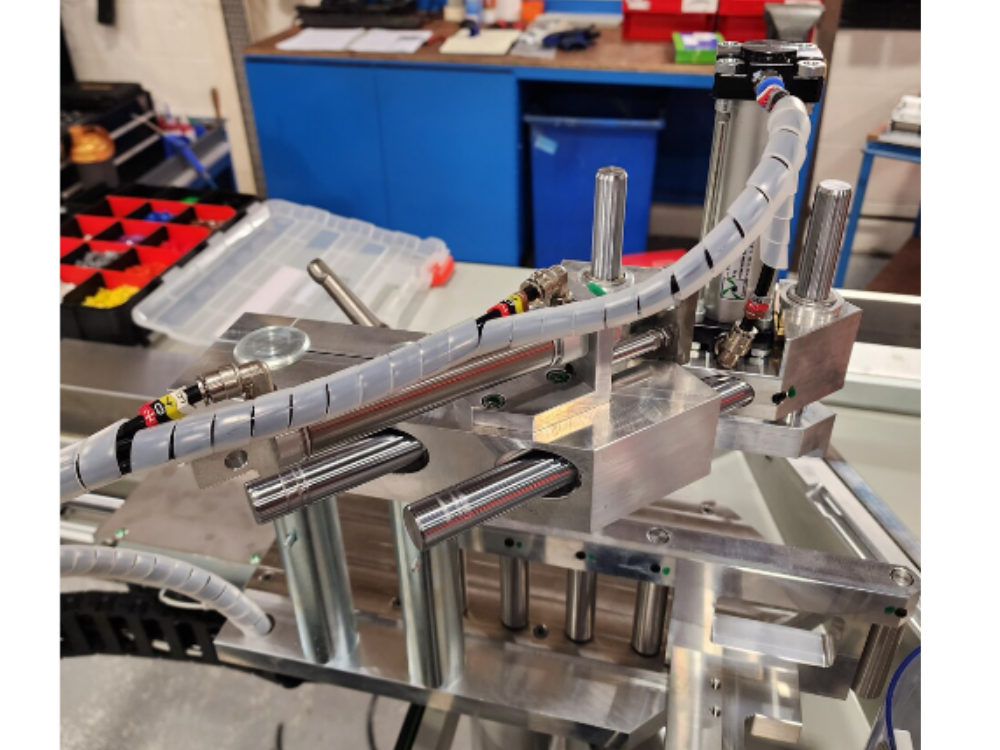
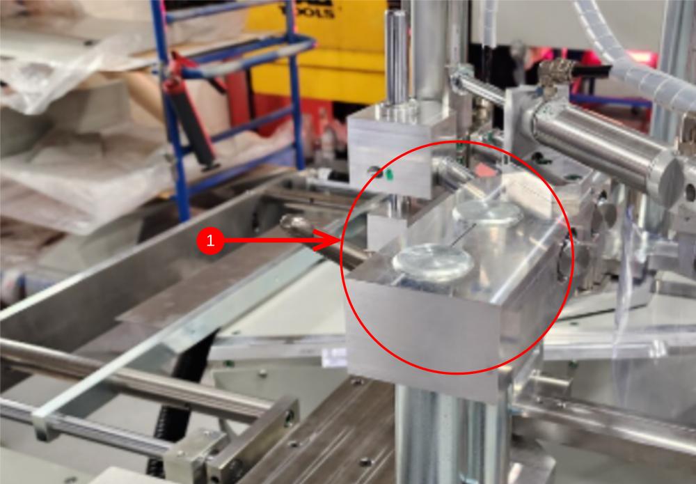
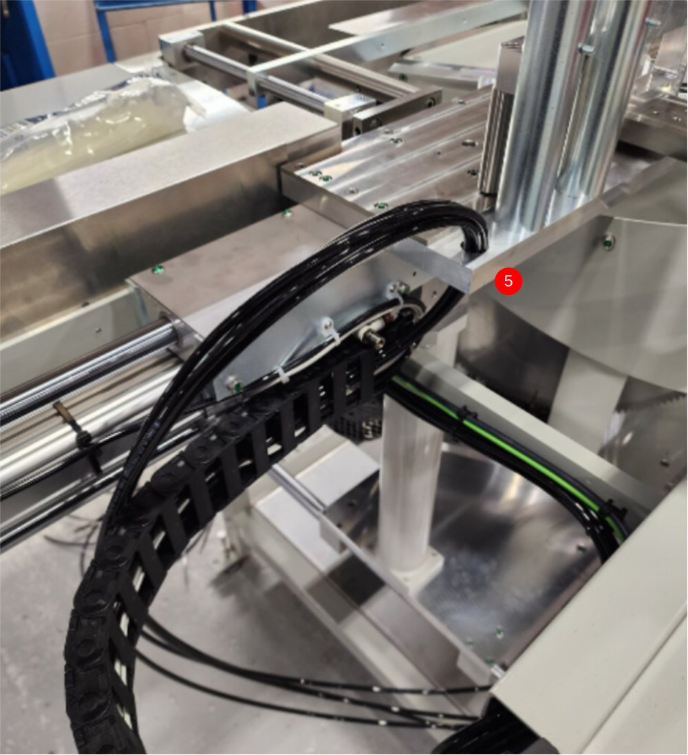
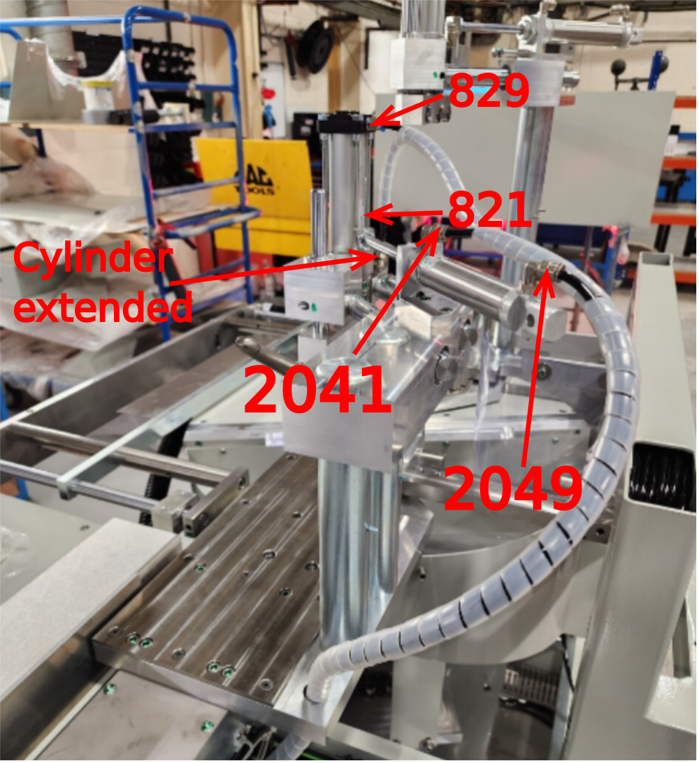
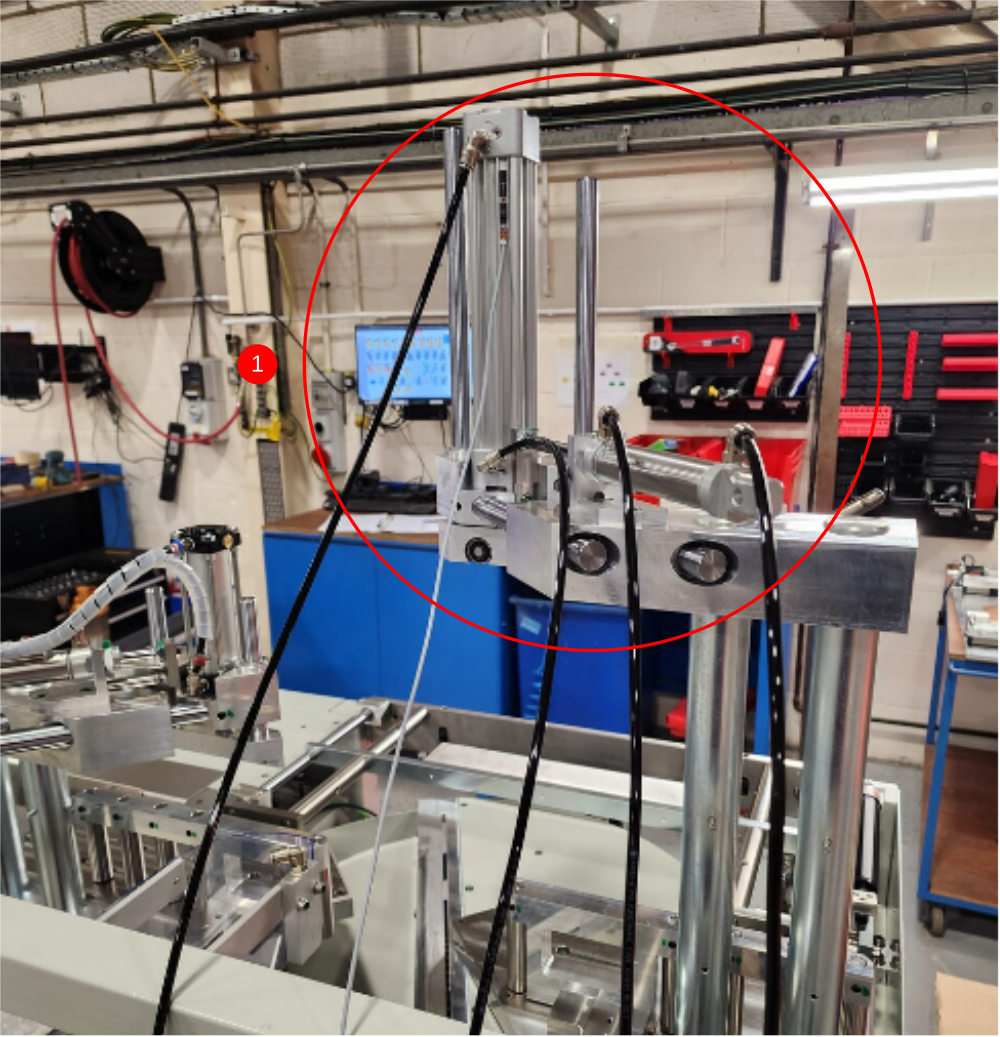
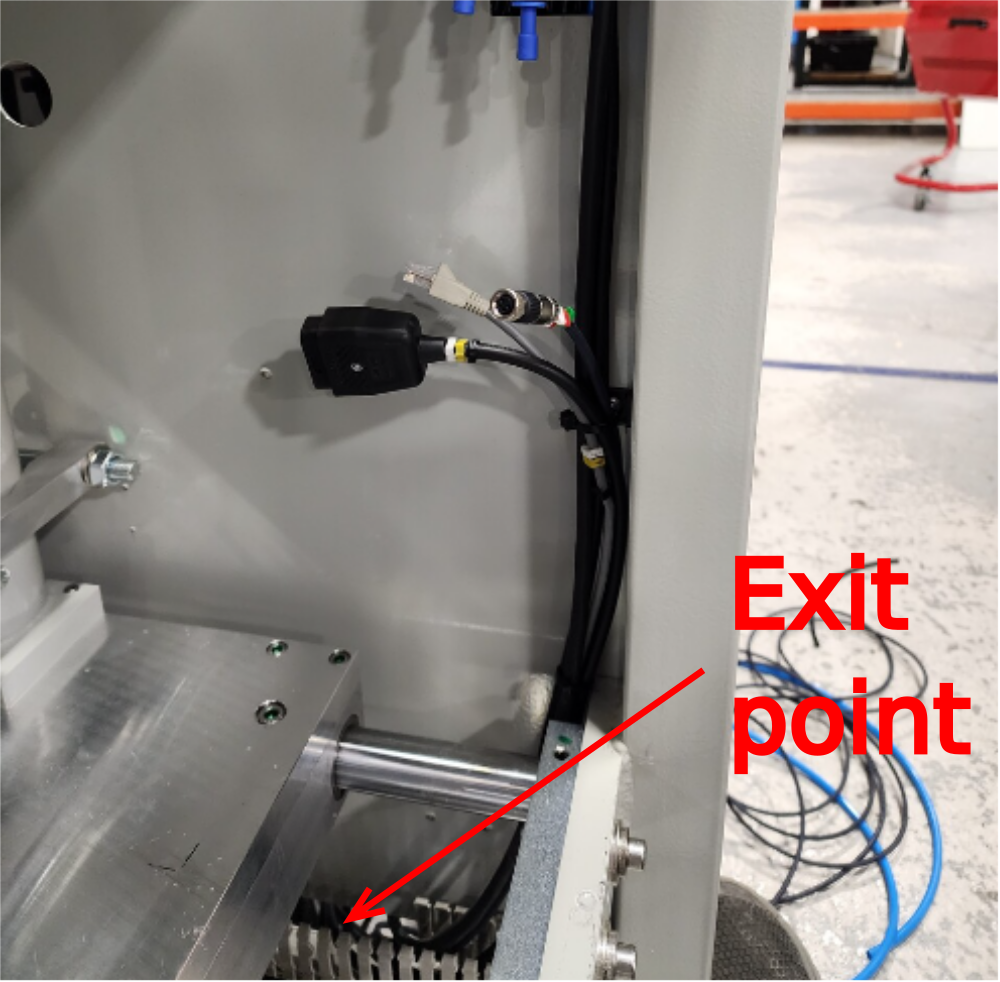
Étape 3 - Y82 Outfeed top clamp Y204 Clamp position
1 Ensure clamp assembly is lifted to the highest position
2 Cut 4 off 6mm black air pipes at 5 meters long
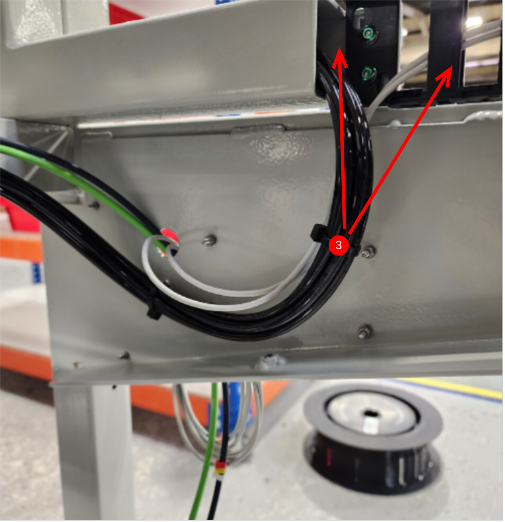
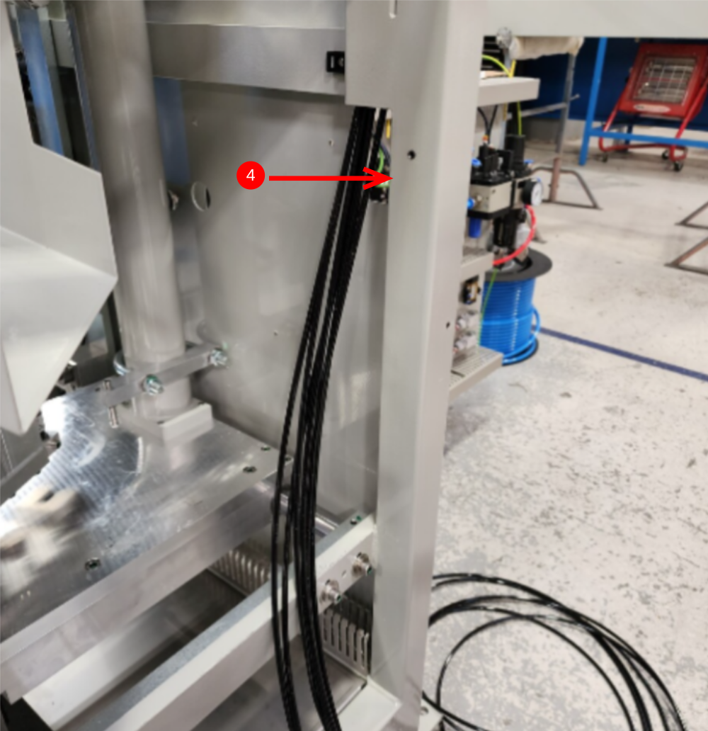
3 Route cables through energy chain and box section
4 Exit pipes here , and use air to blow through and identify as 821.829,2041 and 2049
5 Insert loom through cut table hole then wrapped in large spiral wrap
6 Connect cylinders as shown, ensure cylinder shown is fully extended

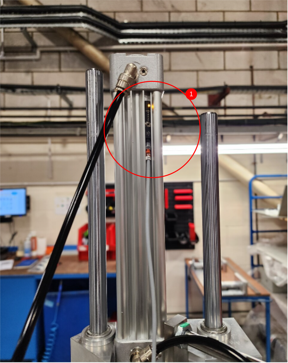
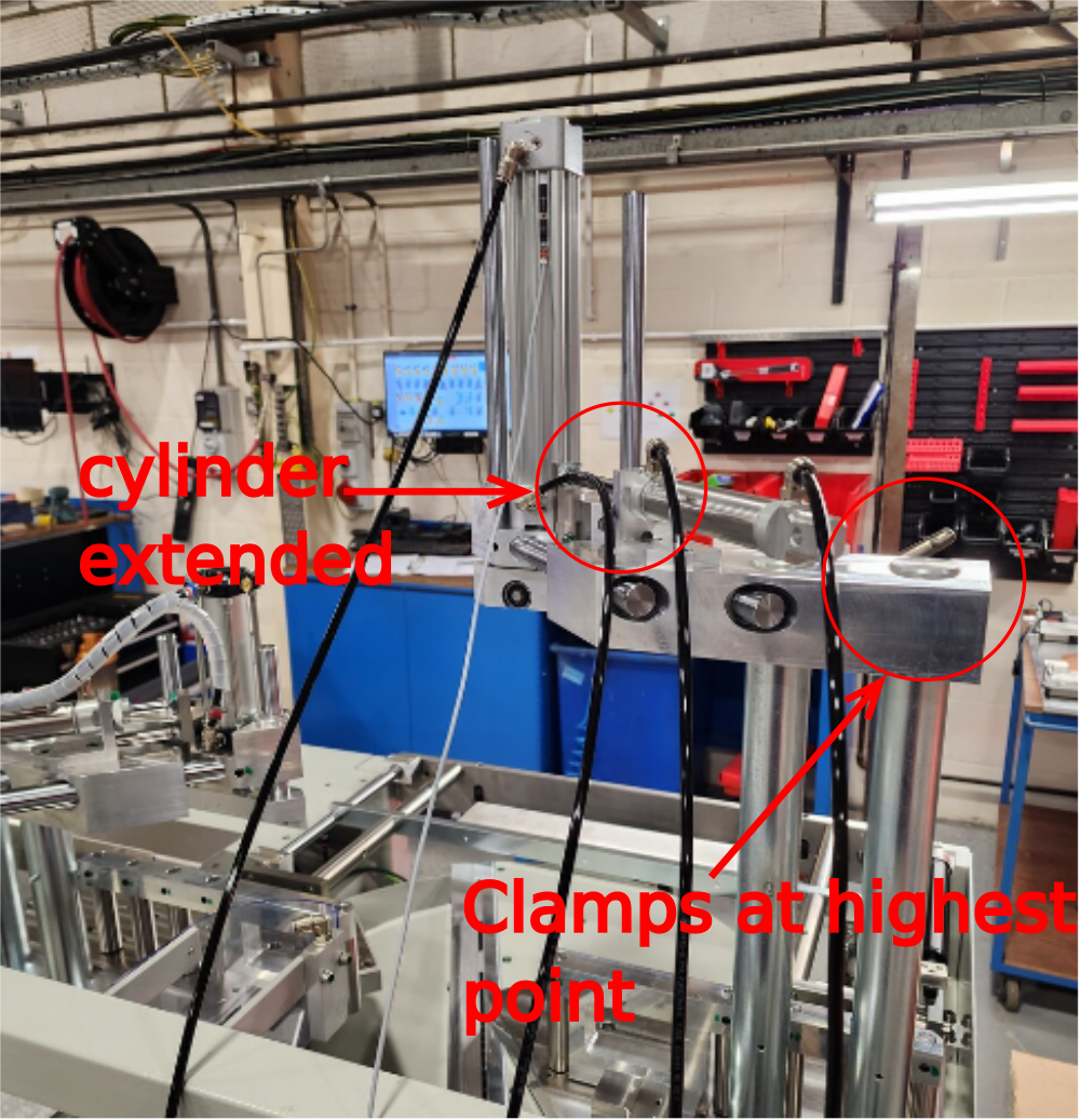
Étape 4 - Y80 Infeed Top clamp and Y204 Clamp position
1 Ensure Clamp assembly is lifted to highest position and extended out
2 Cut 4 off 6mm black air pipes at 4 meters long
3 Retrieve cable CBX138 from electrical loom box
4 Fit and set position of CBX138 using test box. Switch to read when clamp is at home position (up)
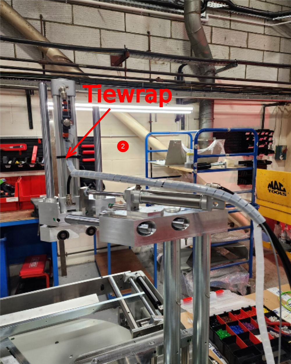
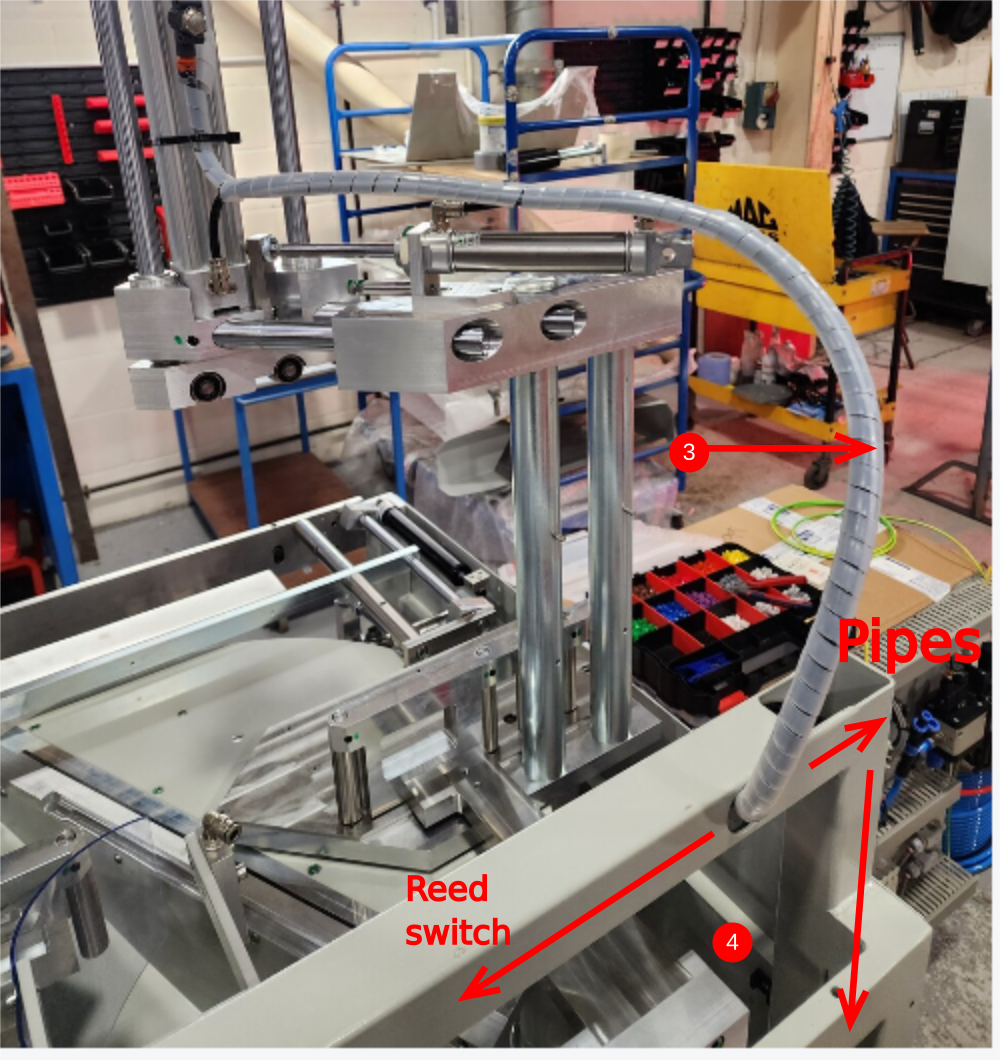
Étape 5 - Y80 Infeed Top clamp and Y204 Clamp position
1 Attach 6mm black pipes as shown
2 Add P0000551 to position shown, and loom pipes and reed switch adding tiewrap to secure to cylinder
3 Loom should enter box section at shown point, no spiral wrap required once entering frame > Keep loom as short as possible in this position
4 Reed switch and pipes will travel separate directions
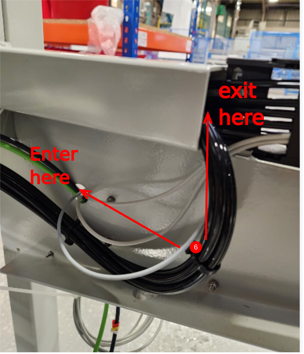
5 Exit pipes at this point , through cut out
6 Exit reed switch at this point, and join with eject reed switches through exit hole

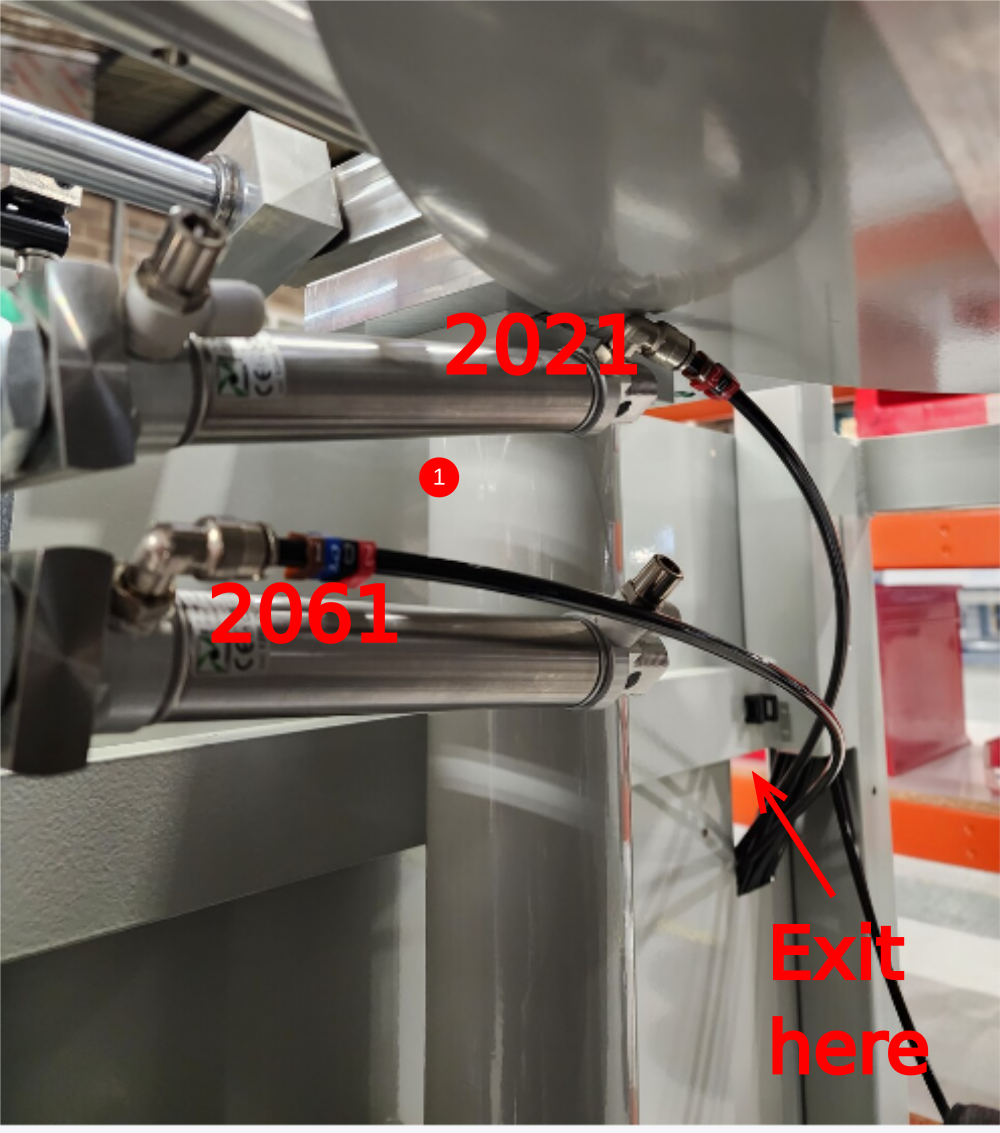
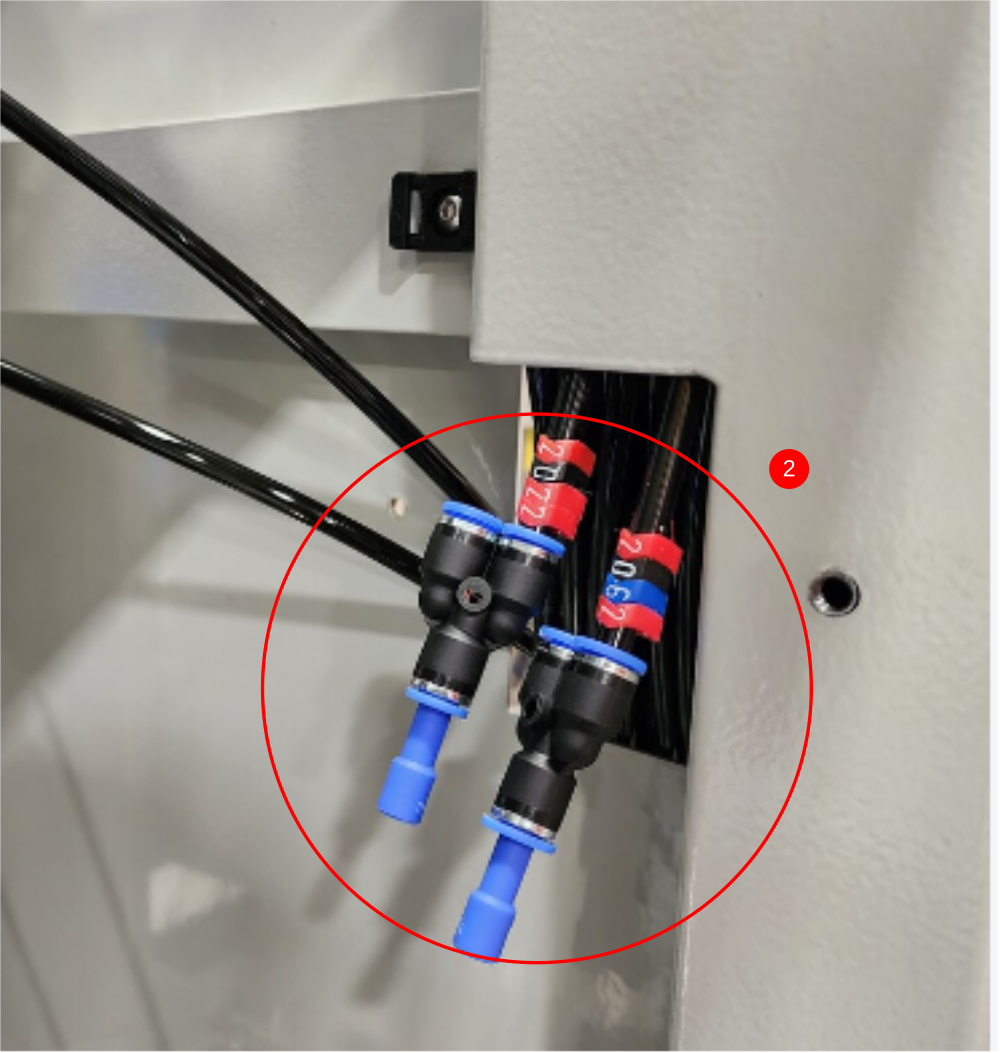
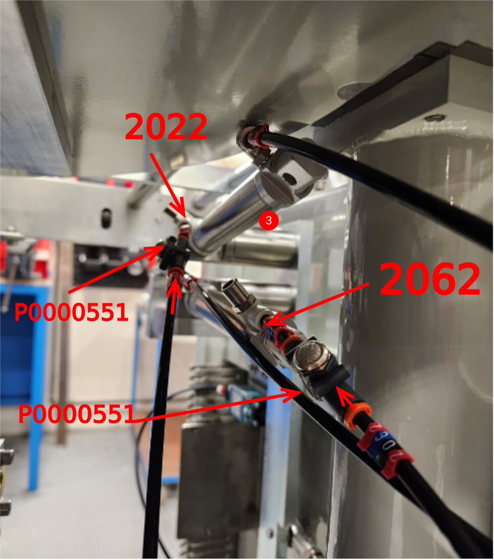
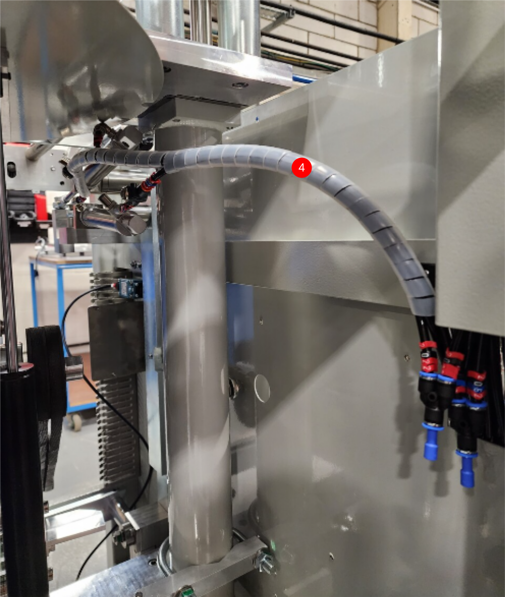
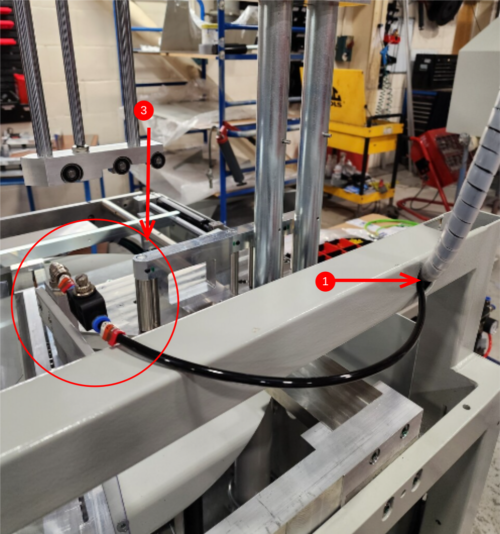
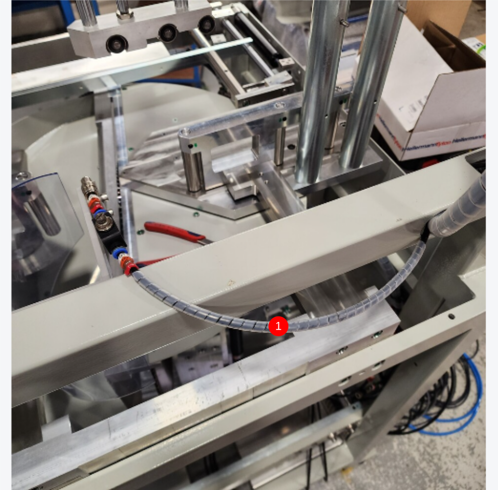
Étape 6 - Y202 side clamp and Y206 centralise
1 Cut 2 off 6mm black pipes at 2.5 meters identify as 2021 and 2061 and connect as shown , with pipes exiting through cutout
2 Fit 6mm Y connectors and blanks as shown to existing lines 2022 and 2062
3 Connect 2 off 6mm black pipes 2022 and 2062 to cylinders, incorporating P0000551 as shown
4 Loom as shown and connect to 6mm y fittings . Ensure loom is correct length to allow full movement of bottom table but short as possible
Étape 7 - Front Cable Loom
1 Continue loom of pre installed cables EC05F and 24F left flying. Bring into loom cable 41F for front guard and use spiral wrap to run loom as shown . Captivate onto pre installed 1st tie base as shown


Étape 8 - Y207 Saw cut conduit cables
1 Cut 2 off 6mm black airpipes at 5.5 meters and run through saw anaconda
2 Retrieve 01F cable and 15F cable from wiring loom box and run through saw anaconda
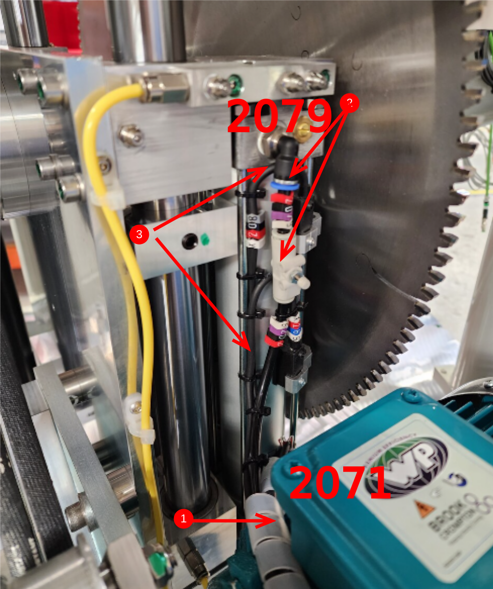
Étape 9 - Y207 connection loom
1 use spiral wrap to loom cables and pipes exiting saw anaconda until saw connection box is reached
2 Exit cable 15F from loom (this will terminate into connection box later)
3 Exit cable 01F from loom one wrap later
4 Incorporate reed switch cables into loom (running from cylinder )
5 Continue loom towards cut cylinder
6 Captivate loom with tie wrap onto pre fitted tie base
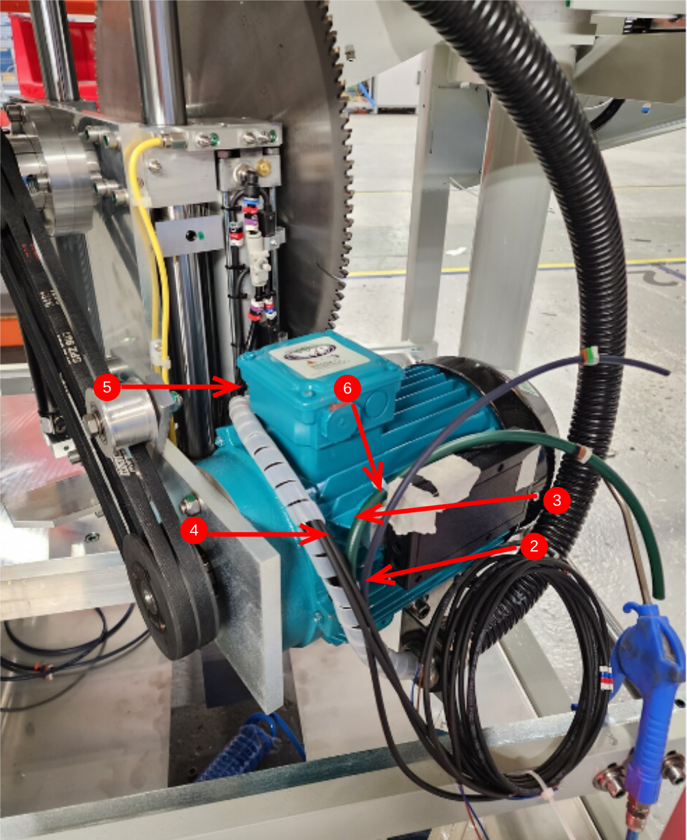
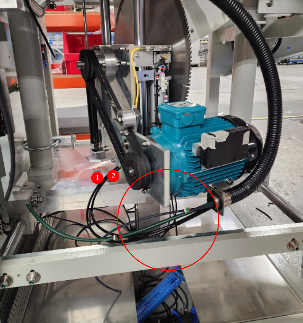
Étape 10 - Y207 Cylinder connections
1 Connect 1 6mm pipe to nose port of cylinder
2 Connect 1 6mm pipe to base of cylinder, incorporating flow controller
3 Ensure reed switch cables and pipes are loomed exactly as shown due to minimal clearance in operation
4 Once pipes are connected, use air to blow through and identify pipes are add idents accordingly
5 Continue spiral wrap of top loom to point shown , fixing on second tie base


Étape 11 - Fit rear cables
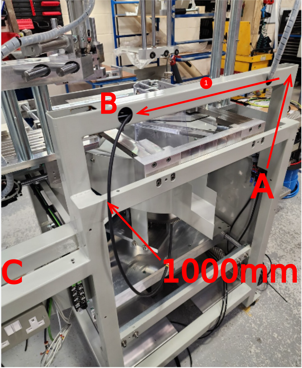
1 Run pre assembled cable 42F from point A to B
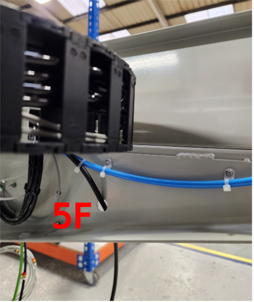
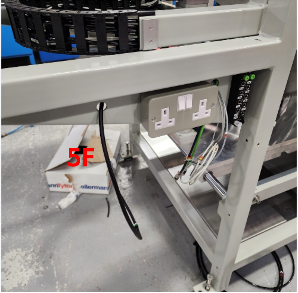
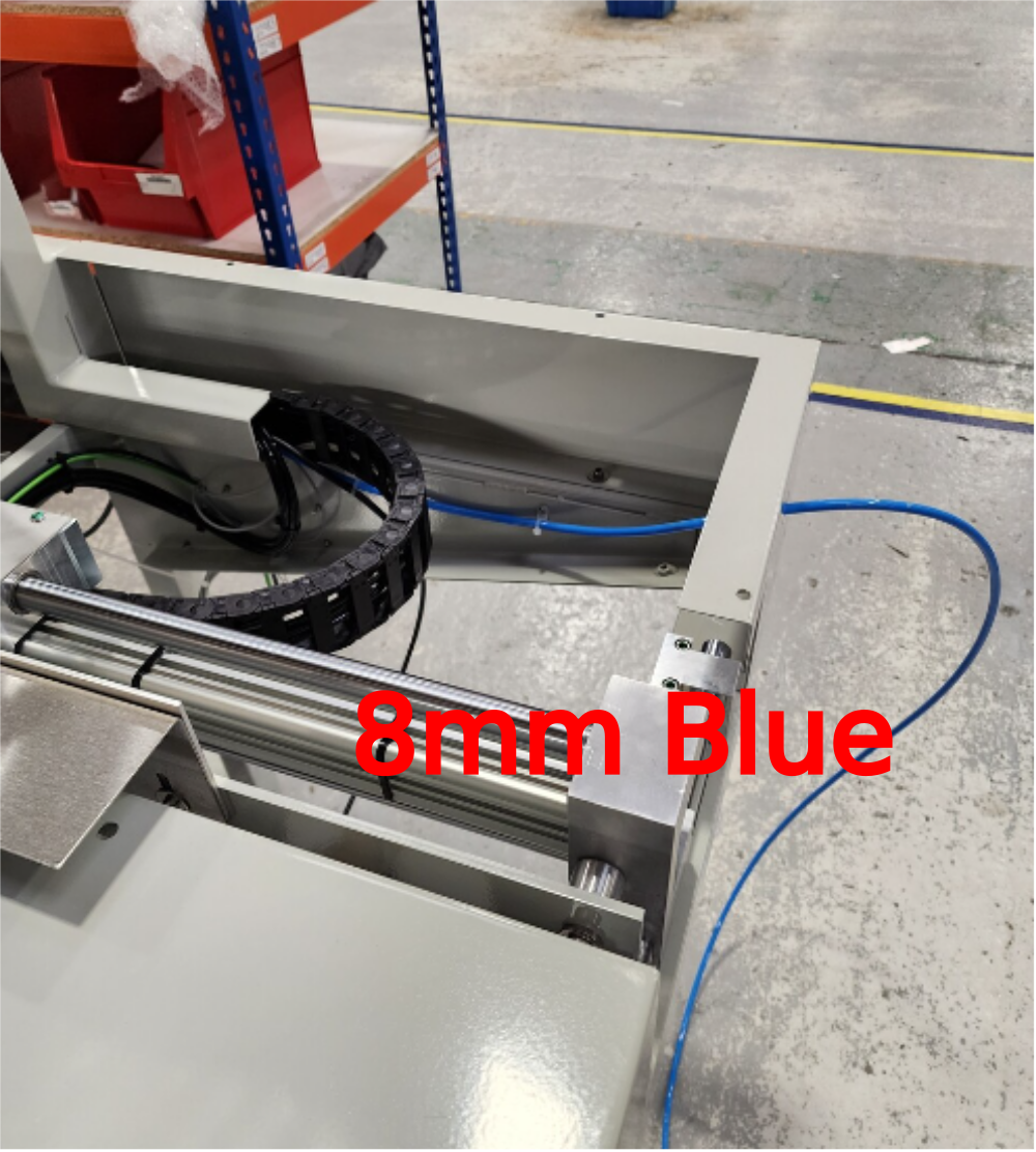
2 Run pre assembled cable 5F and 1 off 8mm blue pipe at 7meters long from point A to point C. 5F cable then routes as shown . 8mm blue pipe routes as shown
Étape 12 - Fit rear hood connections
Captivate pre made cables as shown
04F, 52F and 4F
All cables fitted in steps 10 and 11 now can exit lower slot in trunking
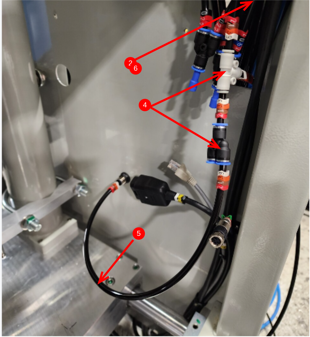
Étape 13 - Y213 Blower 1 and 2
1 1 off 6mm black pipe to enter box section as shown
2 Exit at this point
3 Add in line flow control , and identification numbers and attach to blower
4 Add Tee and Y fitting and identification numbers
5 Add additional 6mm pipe to connect blower bulkhead as shown

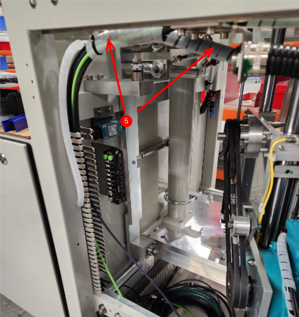
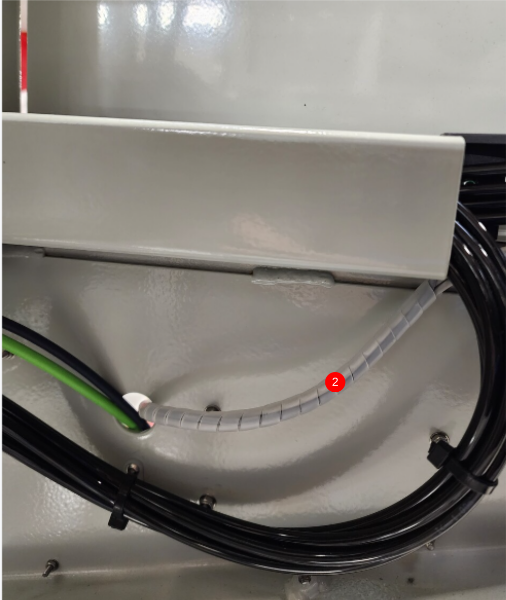
Étape 14 - Fit small Spiral wrap
1 Fit spiral wrap to Saw blower as shown
2 Fit spiral wrap to cables as shown
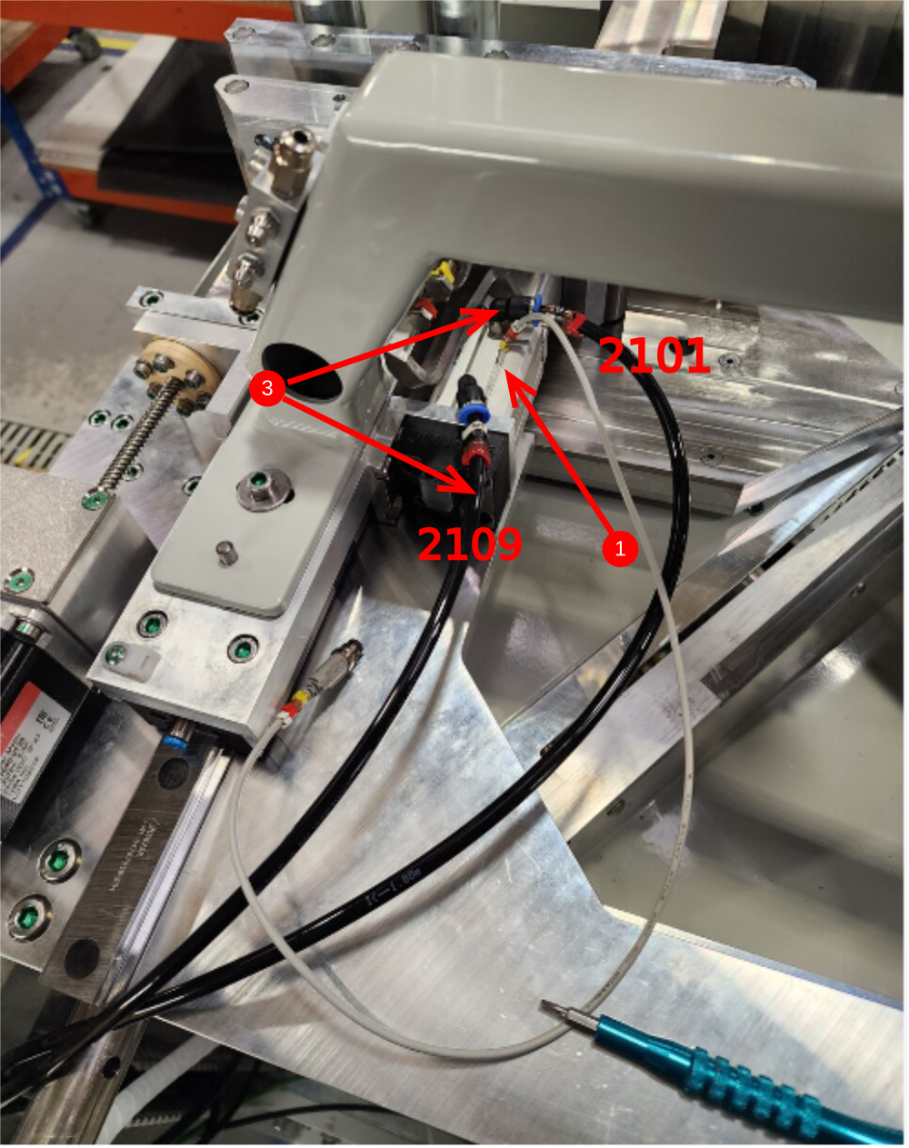
Étape 15 - Y210 Z Support and Y213 Blower
1 Attach pre made cable X214 and fit to infeed z turret cylinder as shown. Use test box to set in correct position. Sensor to read when z block is home position (retracted)
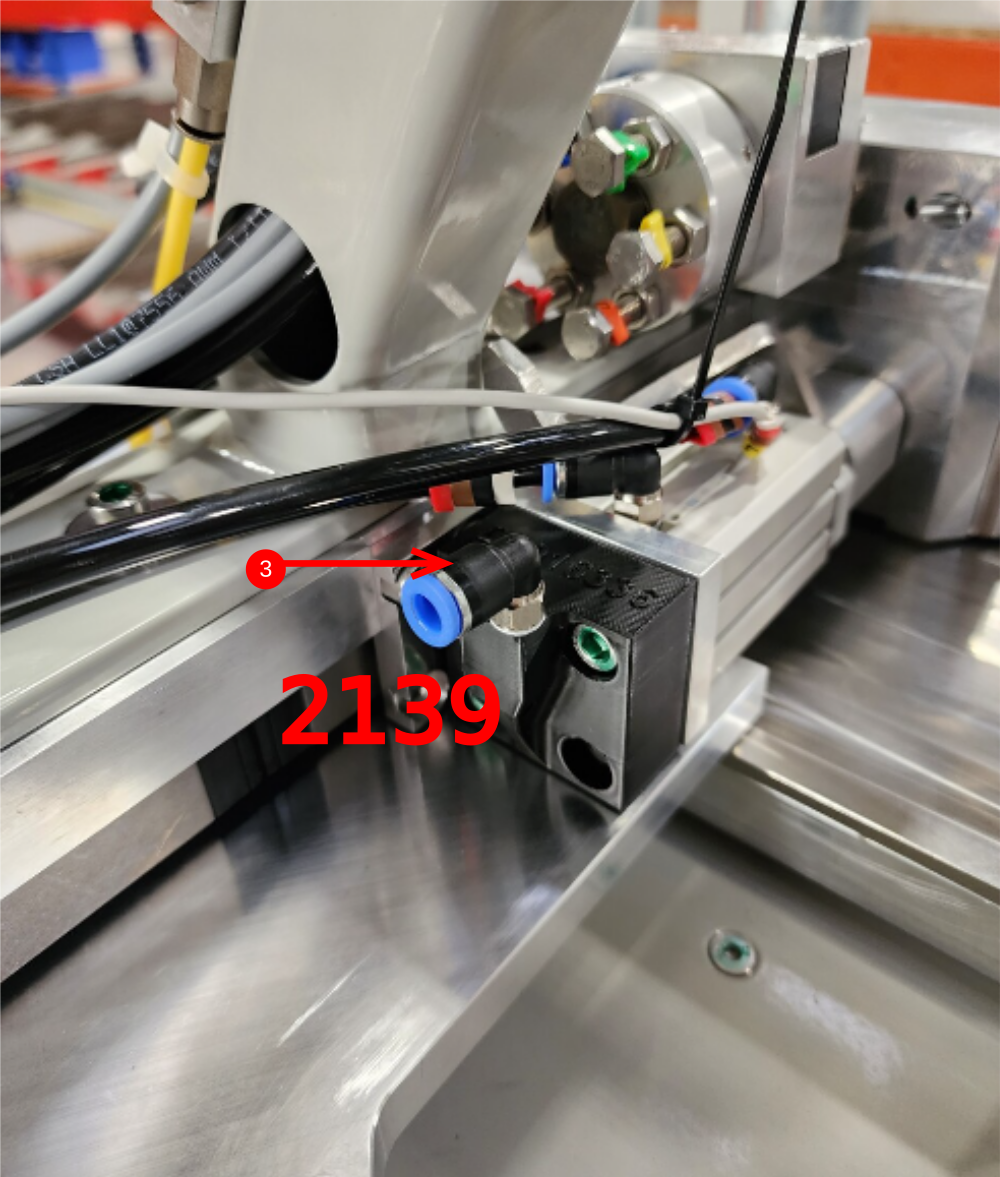
2 Use 3 off 6mm black airpipes at 5 meters long, and identify as 2101,2109 and 2139
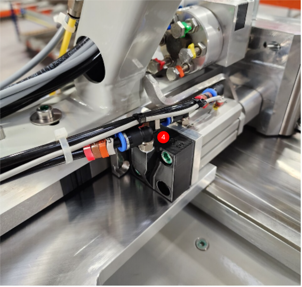
3 Connect to cylinder and blower as shown
4 cable tie loom as shown
Draft
 Français
 English
 Deutsch
 Español
 Italiano
 Português