Details to install pneumatic and electrical loom

Difficulté
Difficile
Durée
1 minute(s)
Introduction
This instruction is to incorporate assembly R0015033B Module F Wiring loom alongside this
See Electrical department for prepared components from above assembly
Tools Required
Pipe cutters
Pipe identification markers
Flush cutters
Parts Required
P0000010 6mm 1/8 elbow fitting x 6 P0000046 Fitting: 'Y' Adaptor 6mm x 6
P0000047 Bulkhead Elbow 6mm x 1
P0000159 Fitting: Stem Blanking Plug 6mm x 2
P0000160 Fitting: Flow Controller In Line 6mm x 2
P0000551 6mm inline Quick Exhaust Fitting x 3
P0001030 Fitting: SMC 6mm Equal Tee x 1
P0001008 regulator x 3
P0001009 Regulator nut x 3
P0001106 Plug in reducer 12-8mm x 1
P0001107 Fitting 12mm equal tee x 1
P0001166 12mm tube to tube elbow x 1Étape 1 - Unless otherwise stated
All bolts to have Loctite 243 adhesive applied unless otherwise stated
All Threaded Pneumatic connections to have Loctite 570 applied
All bolts to be pen marked once adhesive applied and correct tension added

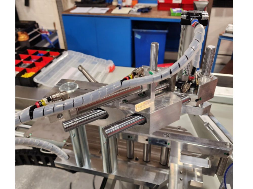
Étape 2 - Y82 Outfeed top clamp Y204 Clamp position
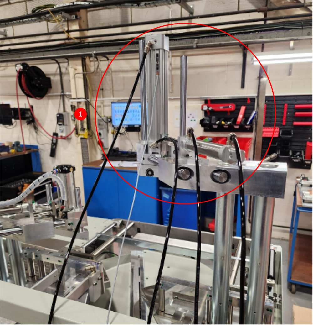
1 Ensure clamp assembly is lifted to the highest position
2 Cut 4 off 6mm black air pipes at 5 meters long
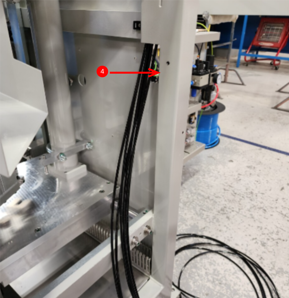
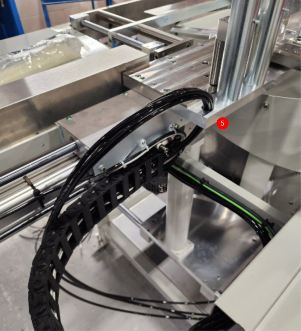
3 Route cables through energy chain and box section
4 Exit pipes here , and use air to blow through and identify as 821.829,2041 and 2049
5 Insert loom through cut table hole then wrapped in large spiral wrap
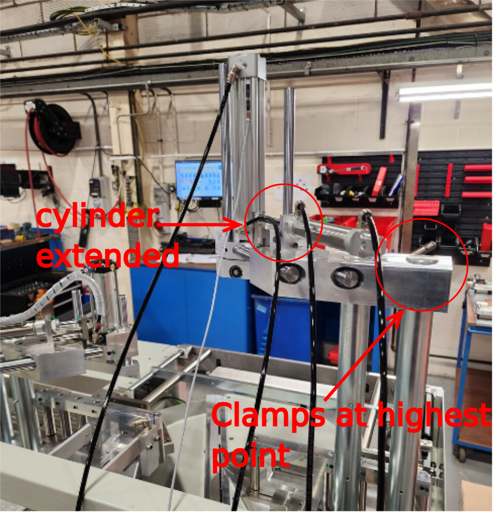
6 Connect cylinders as shown, ensure cylinder shown is fully extended


Étape 3 - Y80 Infeed Top clamp and Y204 Clamp position
1 Ensure Clamp assembly is lifted to highest position and extended out
2 Cut 4 off 6mm black air pipes at 4 meters long
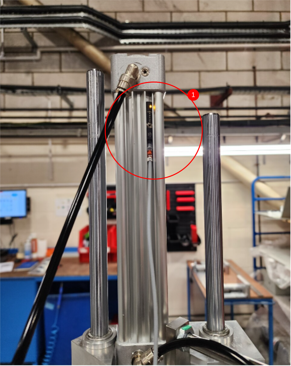
3 Retrieve cable CBX138 from electrical loom box
4 Fit and set position of CBX138 using test box. Switch to read when clamp is at home position (up)
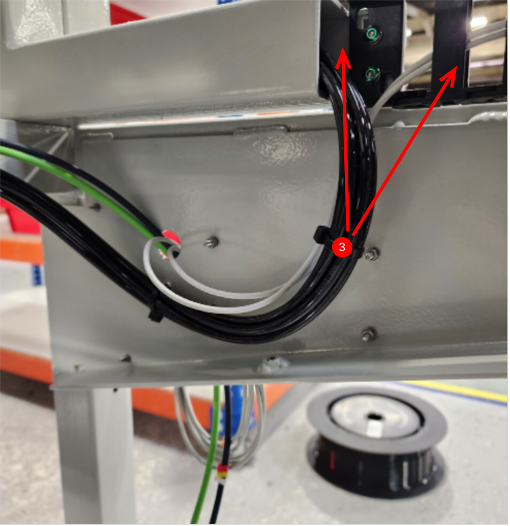
Étape 4 - Y80 Infeed Top clamp and Y204 Clamp position
1 Attach 6mm black pipes as shown
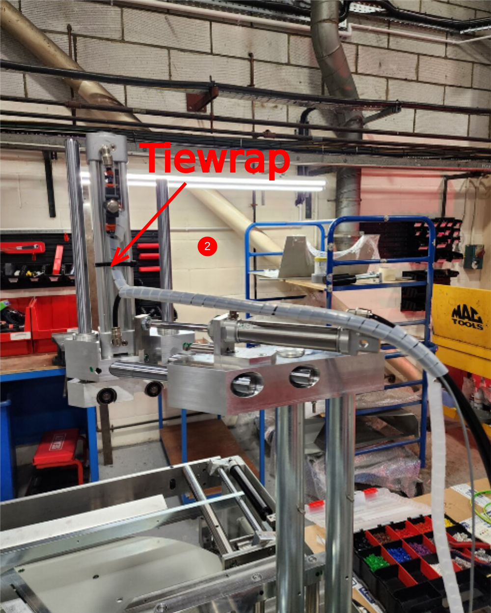
2 Add P0000551 to position shown, and loom pipes and reed switch adding tiewrap to secure to cylinder
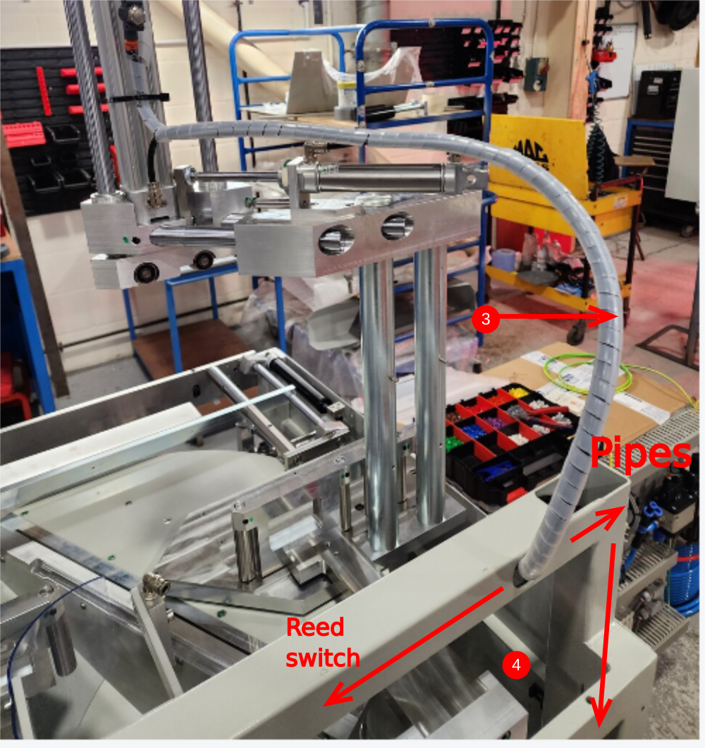
3 Loom should enter box section at shown point, no spiral wrap required once entering frame > Keep loom as short as possible in this position
4 Reed switch and pipes will travel separate directions
5 Exit pipes at this point , through cut out
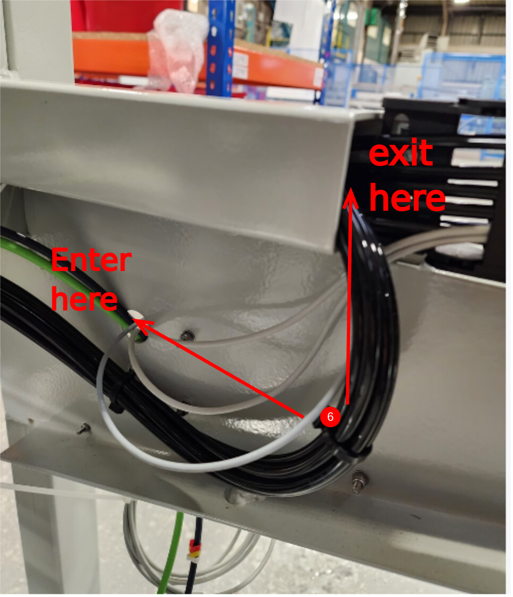
6 Exit reed switch at this point, and join with eject reed switches through exit hole

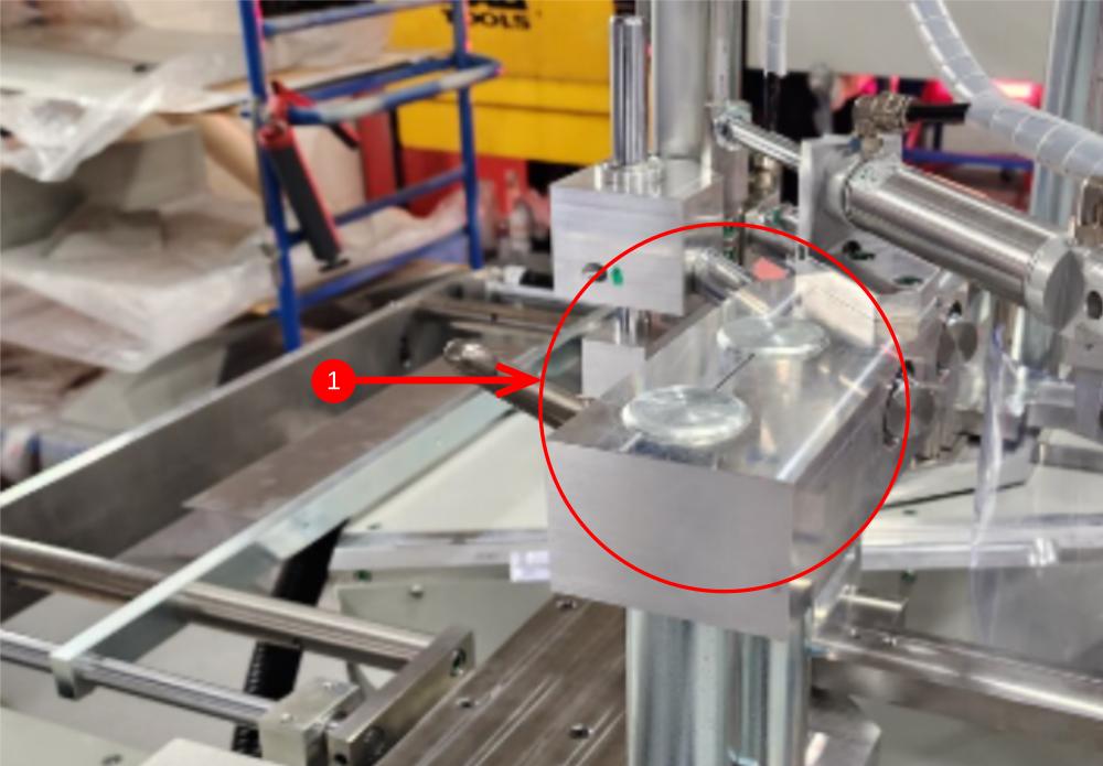
Étape 5 - Y202 side clamp and Y206 centralise
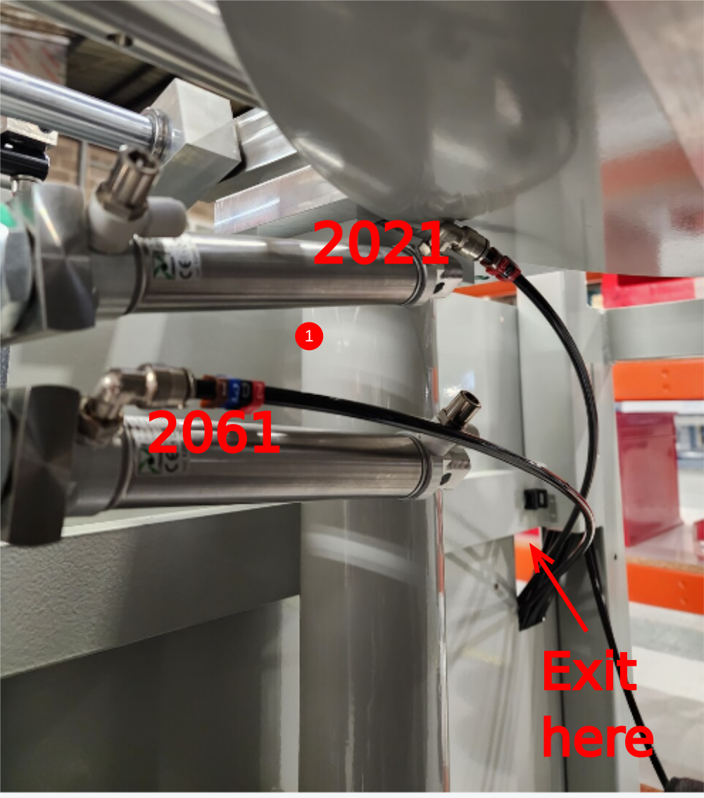
1 Cut 2 off 6mm black pipes at 2.5 meters identify as 2021 and 2061 and connect as shown , with pipes exiting through cutout
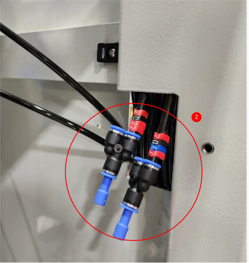
2 Fit 6mm Y connectors and blanks as shown to existing lines 2022 and 2062
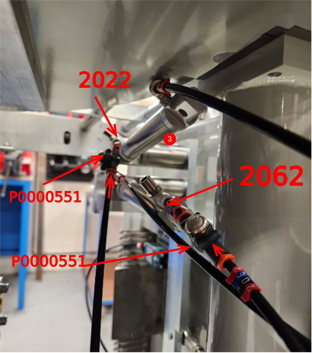
3 Connect 2 off 6mm black pipes 2022 and 2062 to cylinders, incorporating P0000551 as shown
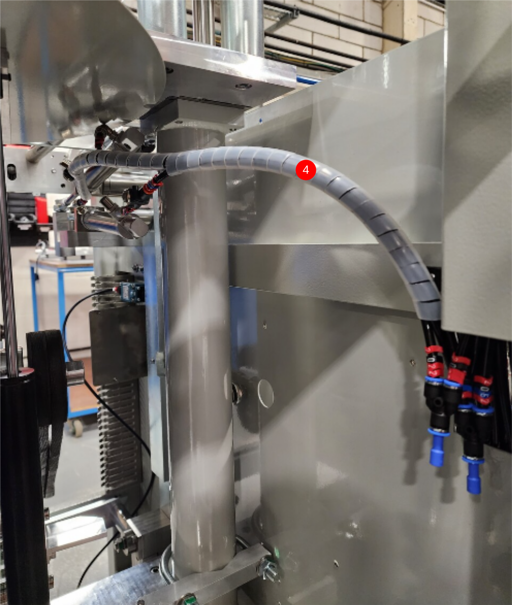
4 Loom as shown and connect to 6mm y fittings . Ensure loom is correct length to allow full movement of bottom table but short as possible
Draft
 Français
 English
 Deutsch
 Español
 Italiano
 Português