Assembly details for pneumatic components

Difficulté
Moyen
Durée
1 heure(s)
Sommaire
- 1 Introduction
- 2 Étape 1 - Unless otherwise stated
- 3 Étape 2 - Ecr raised
- 4 Étape 3 - Assemble valve bank
- 5 Étape 4 - Attach valve bank
- 6 Étape 5 - Assemble regulators
- 7 Étape 6 - Assemble Air service unit
- 8 Étape 7 - Mount air service unit
- 9 Étape 8 - Mount regulators
- 10 Étape 9 - Mount bulkheads
- 11 Étape 10 - Assemble and mount 0-2bar regulator
- 12 Étape 11 - Fit and connect air gun assembly
- 13 Étape 12 - Fit cable gland
- 14 Étape 13 - Fit labels for regulators
- 15 Étape 14 - Lower rear panel bulklheads
- 16 Étape 15 - Label bulkheads
- 17 Commentaires
Introduction
Tools Required
Standard hex key set
Standard spanner set
Standard HSS drill set
Standard tap set
Parts Required
H0007998 Regulator internal mount 5 way x 1
P0000010 Elbow Adaptor 6mm - 1/8 BSPT (Taper thread) x 14
P0000020 Fitting: Plug 1/8" BSP (Grubscrew Type) x 9
P0000021 air gun assembly x 1
P0000024 hex nipple 1/4 x 3
P0000058 Regulator Mounting Kit x 1
P0000074 Elbow Adaptor 8mm - 1/8 BSP (Pneumax not acceptable) x 2
P0000096 Fitting: Brass Reducing Bush 1/2 - 1/4 x 2
P0000142 Elbow Adaptor 8mm - 1/8 BSP x 2
P0000145 tee equal 1/4 x 3
P0000159 Fitting: Stem Blanking Plug 6mm x 2
P0000277 Fitting: Bulkhead Female 8mm x 1/4 BSP x 1
P0000278 Regulator 0-2 bar x 1
P0000332 Regulator with Gauge G1/8'' 0-8 bar x 8
P0000361 1/4'' Male Probe to suit 1/4'' PCL Female coupling x 1
P0000419 Air Service Unit OH (P0283) x 1
P0001071 Valve base type41 8 position x 1
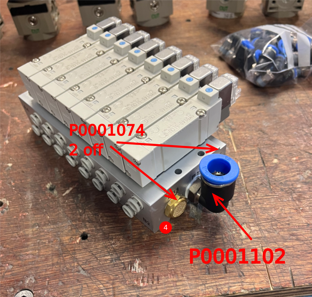
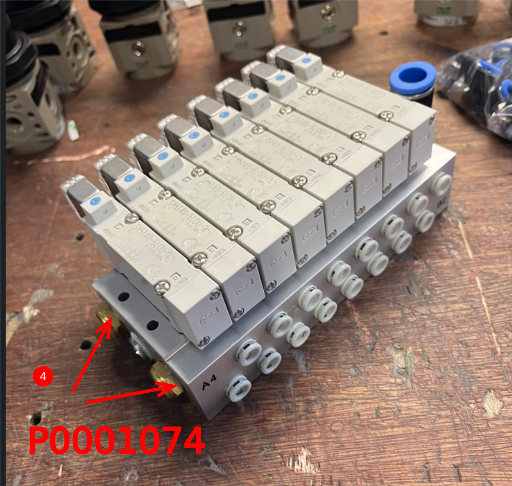
P0001074 Fitting: 1/4" BSP Hex Head Silencer x 4
P0001101 Male straight 1/4 bsp to 12mm x 1
P0001102 Fitting male elbow 12mm 1/4 x 4
P0001105 Bulkhead straight 12mm x 6
P0001186 Valve. 24v dc smc x 8
Étape 1 - Unless otherwise stated
Use Loctite 243 on all fasteners
Use Loctite 572 on all threaded pneumatic connection
Pen mark all fasteners to show finalised

Étape 2 - Ecr raised
Ecr raised to amend regulator bracket to remove redundant holes and add fixing holes for valve bank
Use part as is until process to update is complete
Drill regulator bracket M4 to suit valve base


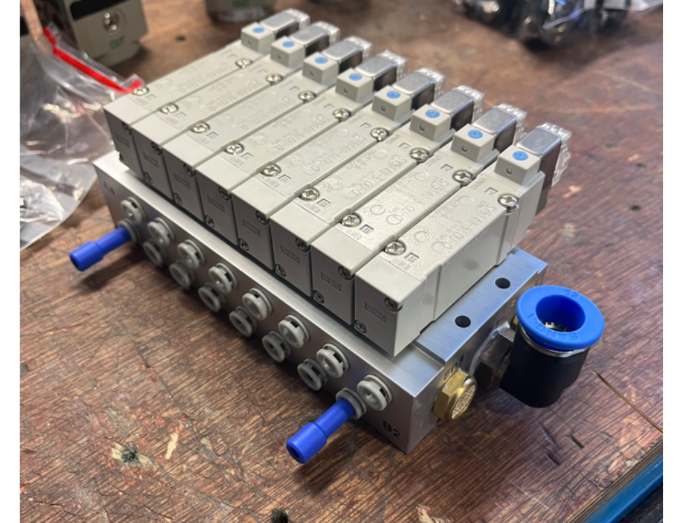
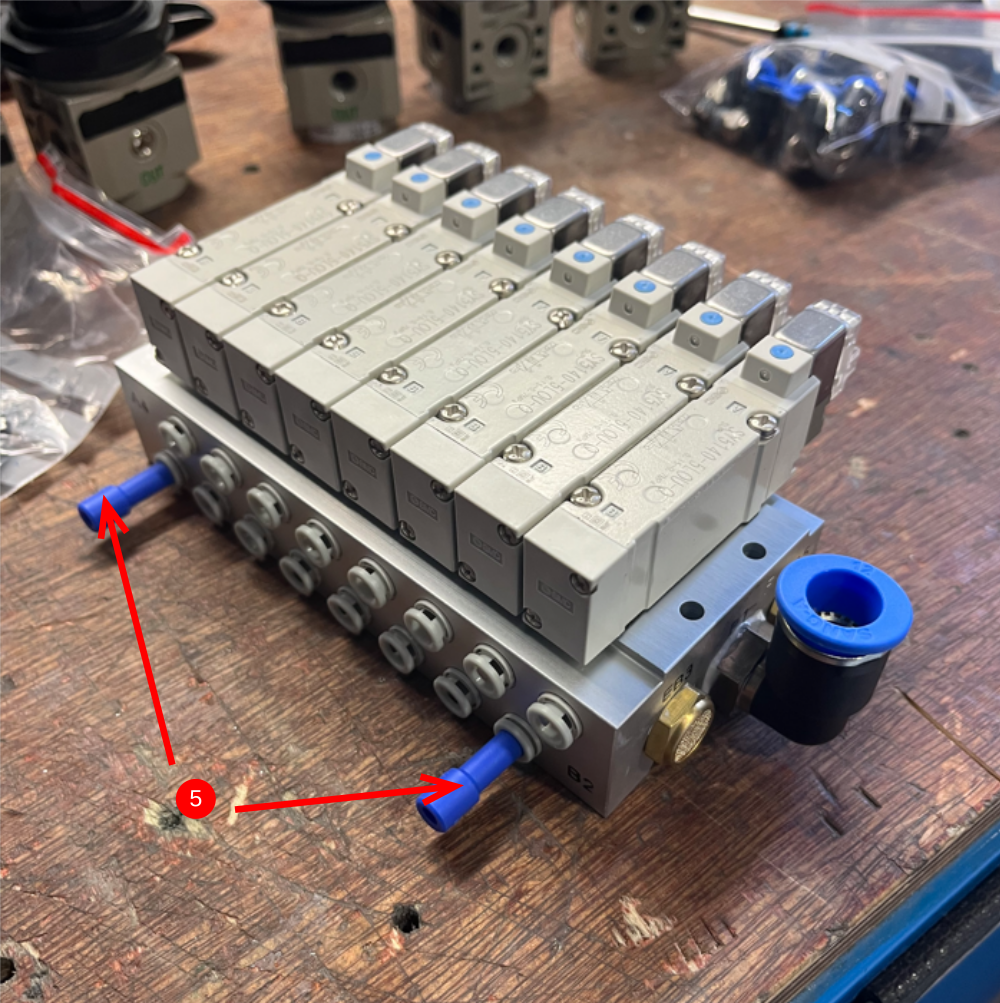
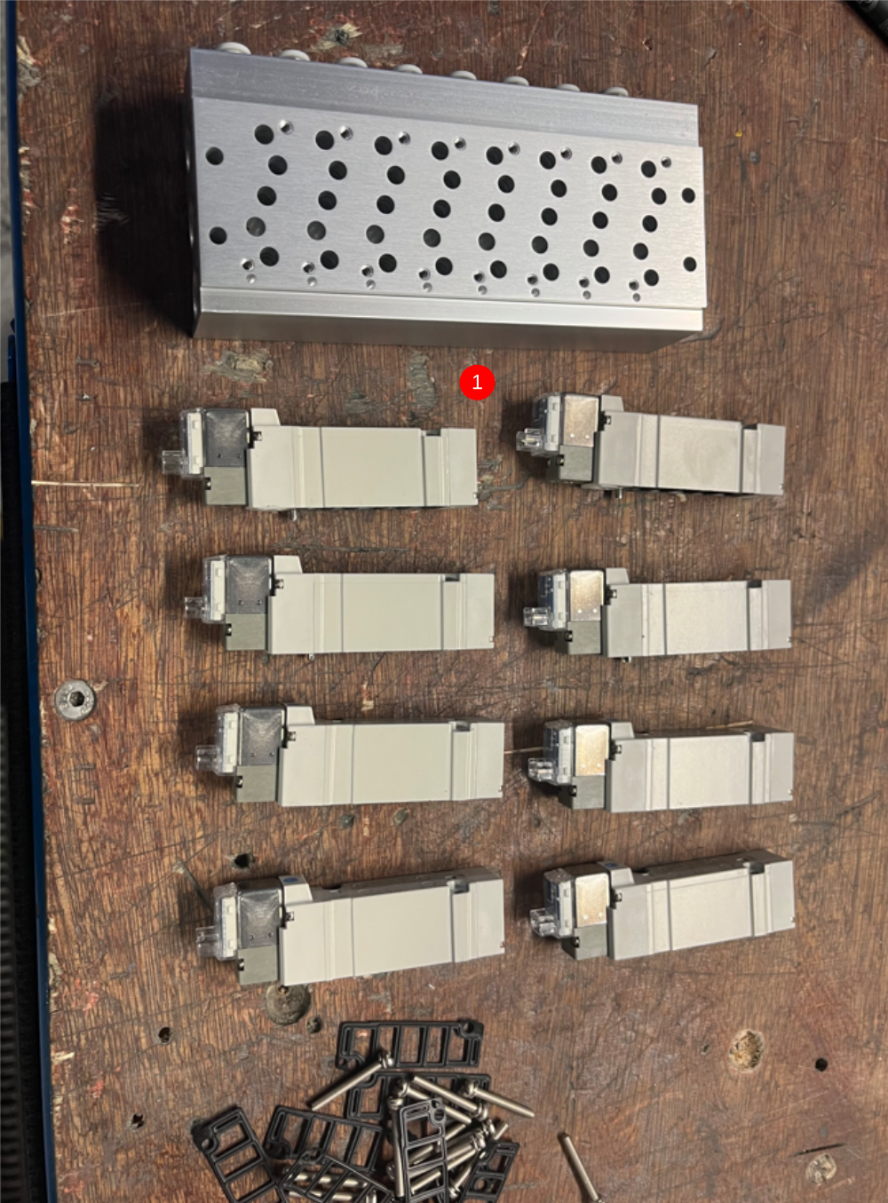
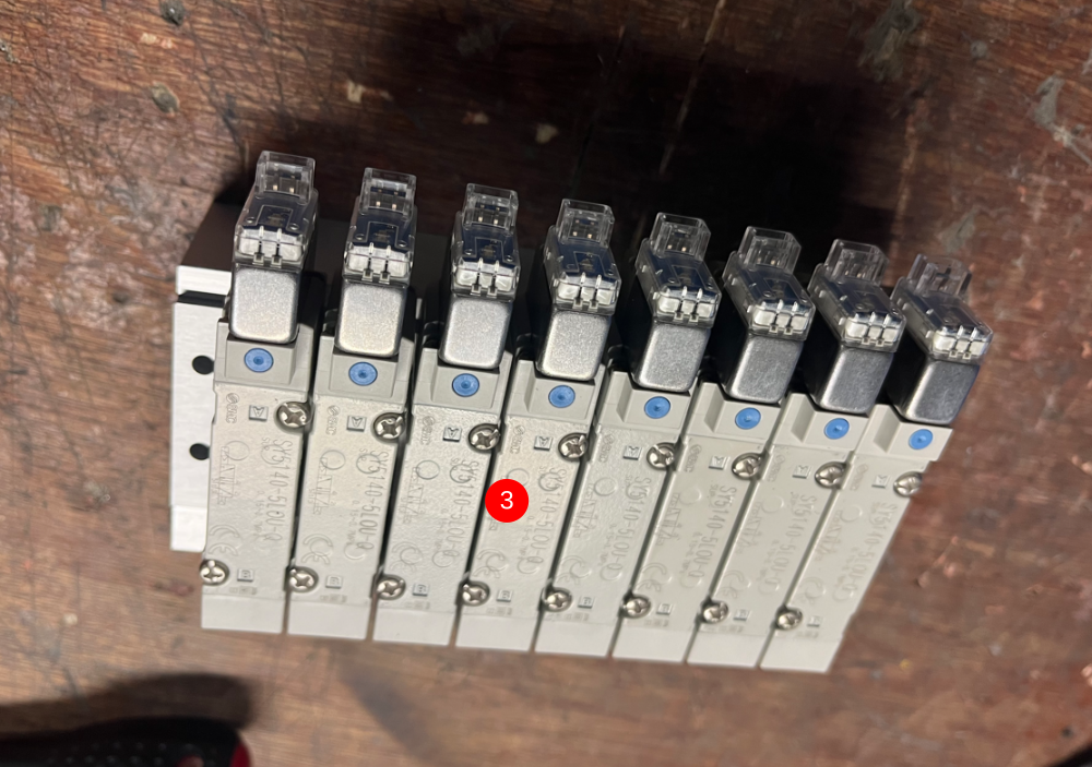
Étape 3 - Assemble valve bank
Assemble valve bank
1 Prepare parts
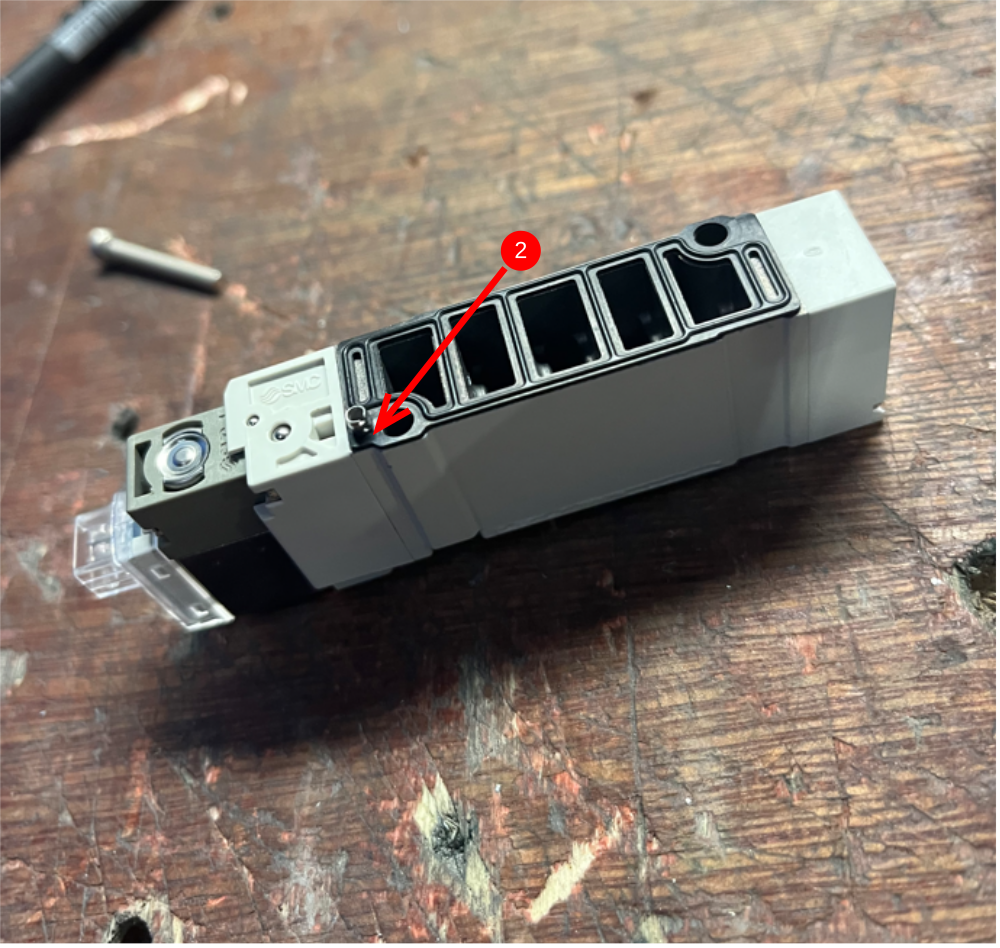
2 Fit gasket to valves . Ensure gasket sits flat and aligned
3 Fit valves to valve bank base
4 Attach Air feed connection and exhausts
5 Add 6mm blanks
Étape 4 - Attach valve bank
Attach valve bank to regulator bracket using M4 socket caps , washers and nyloc nuts

Étape 5 - Assemble regulators
Assemble 7 off regulators with 6mm elbows and spare port blanked
Assemble 1 off regulator with 8mm elbows and spare port blanked

Étape 6 - Assemble Air service unit
Assemble air service unit

Étape 7 - Mount air service unit
Mount air service unit to front lower panel

Étape 8 - Mount regulators
Mount regulators to front lower panel
As viewed from front, bottom right regulator should have 8mm fittings
Étape 9 - Mount bulkheads
Mount 3 off 12mm bulkheads to lower panel
Étape 10 - Assemble and mount 0-2bar regulator
Assemble and mount 0-2 bar regulator to lower front panel
Étape 11 - Fit and connect air gun assembly
Fit 8mm bulkhead to lower front panel
Fit air gun assembly
Connect 8mm red pipe from reg OUT to bulkhead

Étape 12 - Fit cable gland
Fit cable gland for air service unit
Étape 13 - Fit labels for regulators
Print and Attach labels for regulator's
Labels to be added both sides of panel
From top left to bottom right
Y350 Clamp Infeed Top
Y351 Clamp Infeed Side
Y386 Clamp Middle Top
Y386 Clamp middle Side
Y395 Clamp V Top
Y395 clamp V Side
Z Axis Support
VZ Axis Support

Étape 14 - Lower rear panel bulklheads
Fit 3 off 12mm bulkheads to rear lower panel

Étape 15 - Label bulkheads
Print and fit Labels to identify bullheads as
12mm red 2 off
12mm blue 1 off
Draft
 Français
 English
 Deutsch
 Español
 Italiano
 Português