Guarding fitment instructions

Difficulté
Moyen
Durée
4 heure(s)
Sommaire
- 1 Introduction
- 2 Étape 1 - Unless otherwise stated
- 3 Étape 2 - Fit front door
- 4 Étape 3 - Rework D0016266
- 5 Étape 4 - Fit front door interlock assembly
- 6 Étape 5 - Attach interlock key and catch
- 7 Étape 6 - Align interlock and drill Catch
- 8 Étape 7 - Fit serial plate
- 9 Étape 8 - Fit hinge panel to frame
- 10 Étape 9 - Fit chute inserts
- 11 Étape 10 - Fit rear chute
- 12 Étape 11 - Fit rear tray
- 13 Étape 12 - Fit front tray
- 14 Étape 13 - Assemble and fit regulators
- 15 Étape 14 - Fit top hood
- 16 Étape 15 - Finalise position of tip strips
- 17 Étape 16 - Fit blade spanner
- 18 Étape 17 - Fit compliance guards
- 19 Commentaires
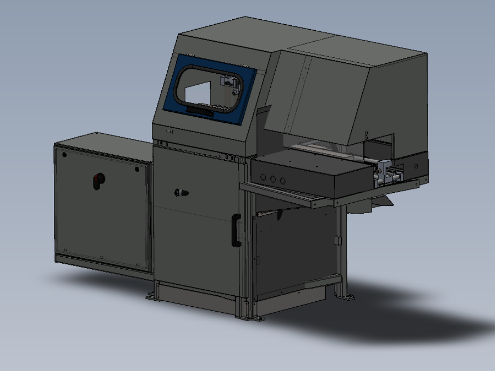
Introduction
Tools Required
Standard hex key set
Standard spanner set
Parts Required
D0001878 Rear Door Saw Mk4 (1879) x 1
D0004584 Outfeed Side Rest x 3
D0015703 Air Gun Bracket x 1
D0016203 Compliance Guard - Saw Lower Front x 1
D0016204 Compliance Guard - Saw Lower Side x 1
D0016265 Saw Front Door: Bernstein Mount Plate x 1
D0016266 Saw Front Door: Bernstein Guard x 1
E0001569 Guard Lock Switch: Bernstein Radius Actuator (Key) x 1
M0000055 Saw Blade Spanner (24mm Combination) x 1
M0001051 Bullet Catch 70 x 12 x 1
P0000010 Elbow Adaptor 6mm - 1/8 BSPT (Taper thread) x 6
P0001008 Regulator: ARG20 0 - 8.5 Bar c/w Gauge x 3
P0001009 Panel Mount Nut (To suit P0001008) x 3
R0015041 Bench Assemble Top Hood Assembly x 1
R0015337 Bench assemble guarding components x 1
R0015338 Bench assemble serial plate x 1
Étape 1 - Unless otherwise stated
All bolts to have Loctite 243 adhesive applied unless otherwise stated
All Threaded Pneumatic connections to have Loctite 570 applied
All bolts to be pen marked once adhesive applied and correct tension added

Étape 2 - Fit front door
Fit pre assembled front door to frame
Use 6 off M4 x 12 button sockets only to fix hinges to frame.
Ensure door sits square to frame


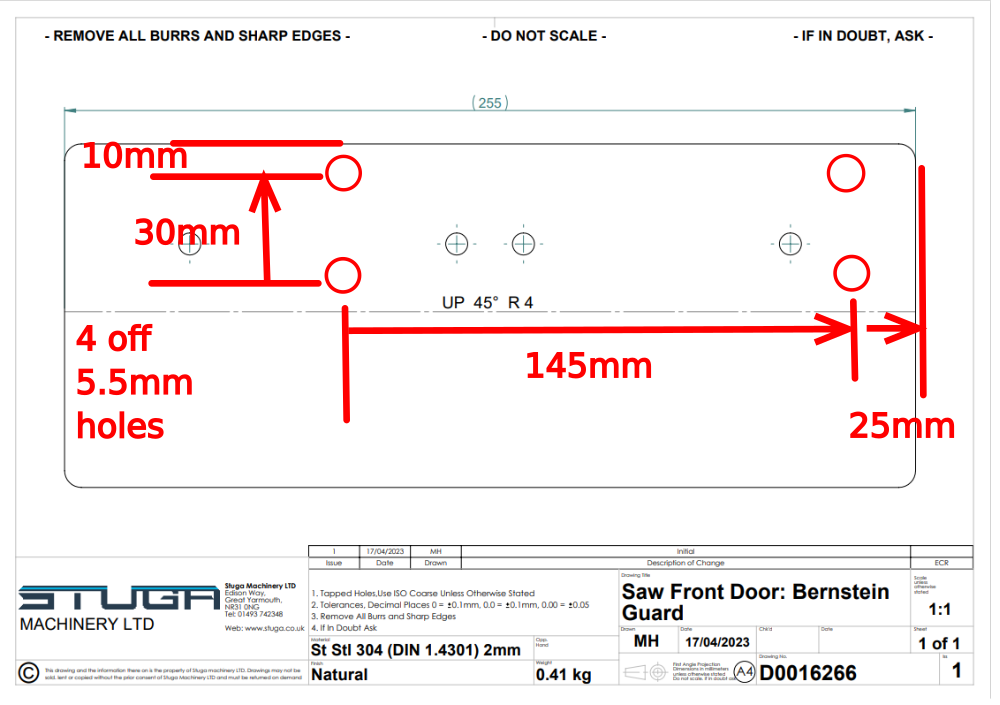
Étape 3 - Rework D0016266
ECR Raised 13/12/23
Rework part to attached dimensions until ECR process issues amended part
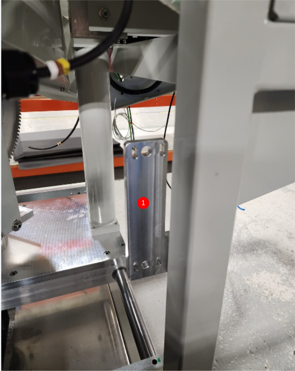
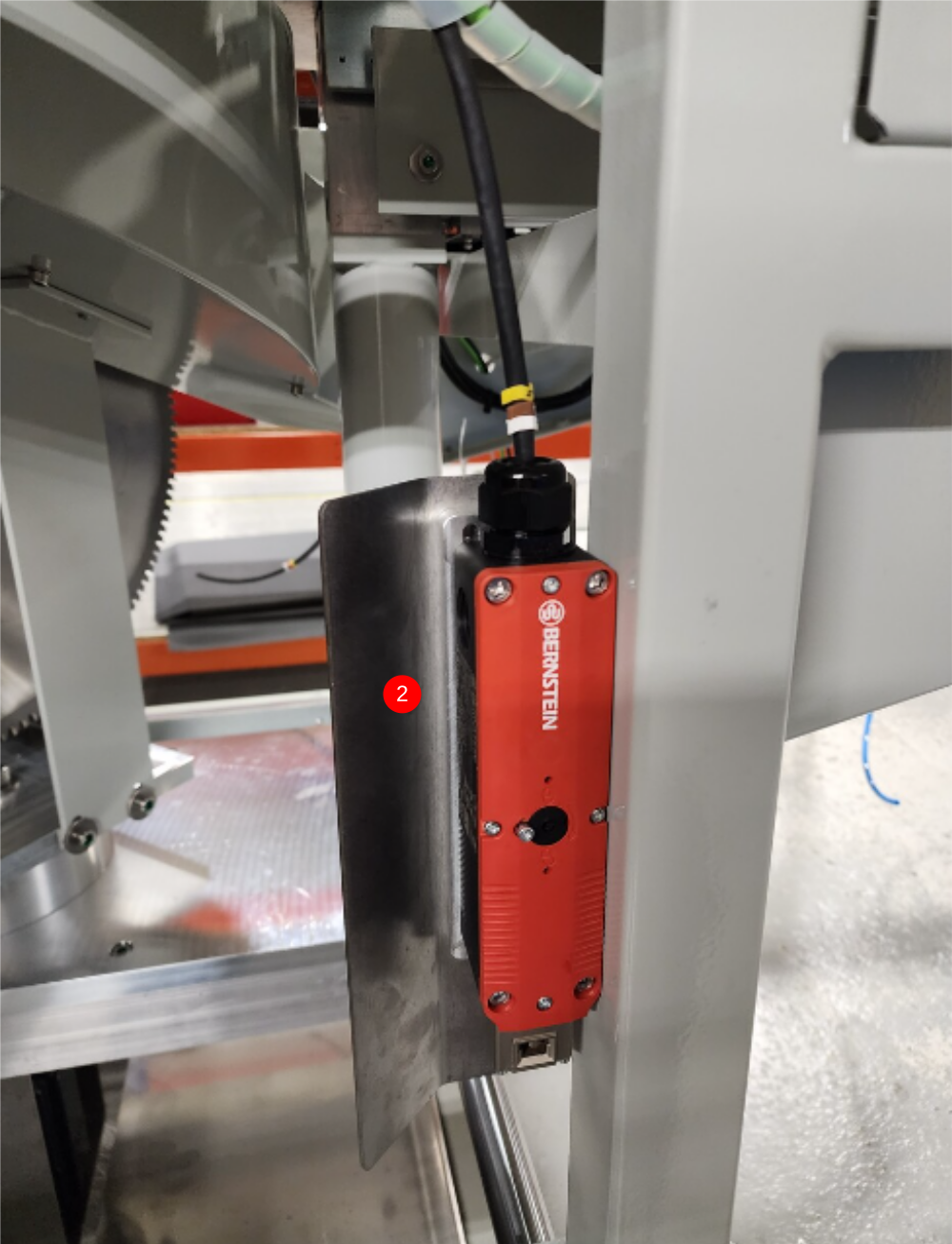
Étape 4 - Fit front door interlock assembly
1 Fit mounting bracket using 2 off M6 x 30 socket caps and heavy M6 washers
2 Attach interlock and guard panel using 4 off M5 x 60 socket caps, M5 penny washers and M5 Nyloc nuts
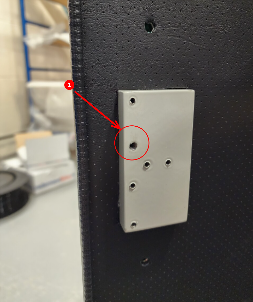
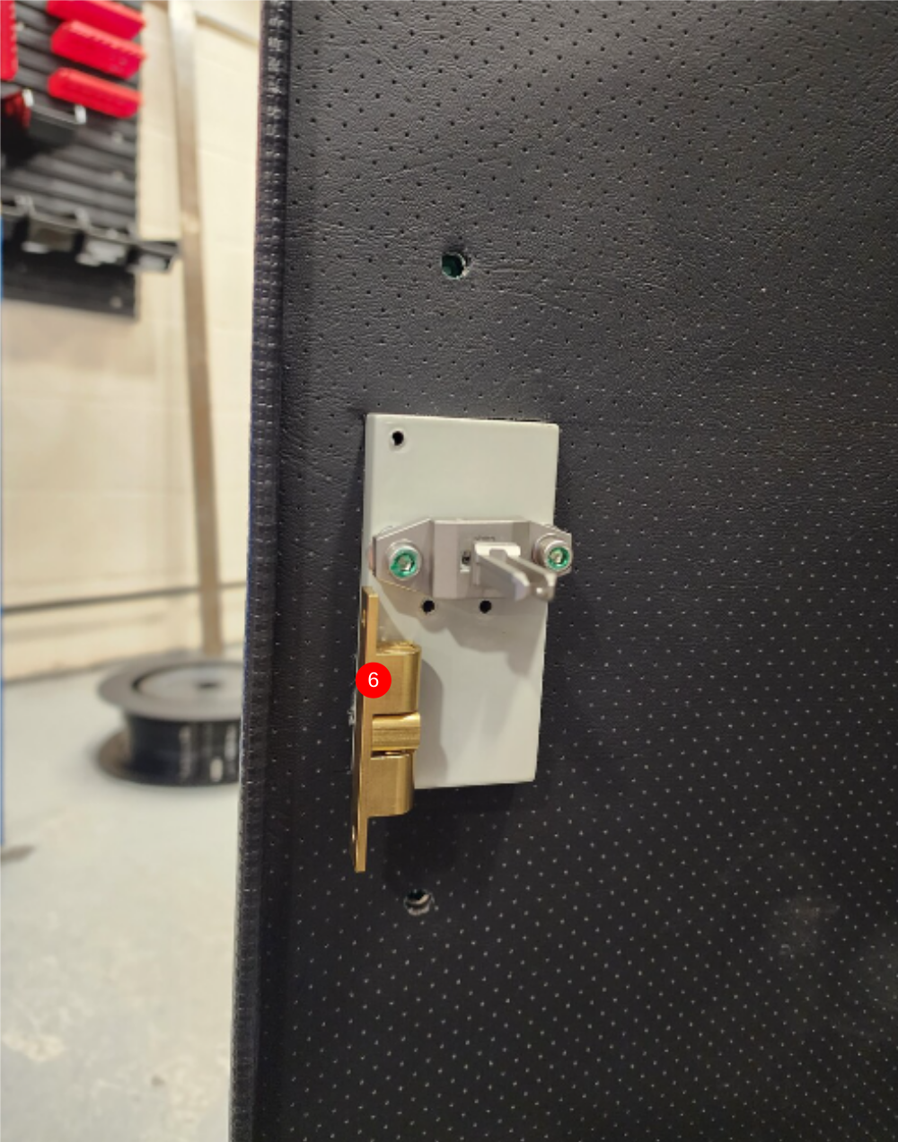
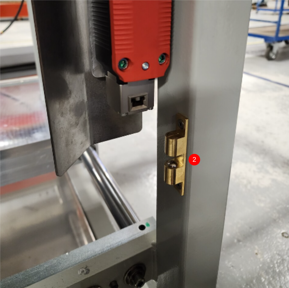
Étape 5 - Attach interlock key and catch
ECR raised to amend door fixing block holes
1 Drill and tap indicated hole to M5
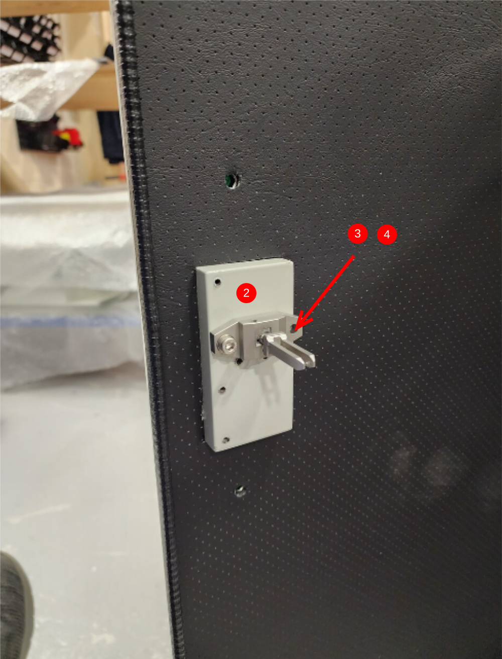
2 Fit interlock blade using 1 off M5 x 20 socket cap and M5 A Forms washer , and align as shown
3 Mark position of second fixing hole and drill and tap to M5.
4 Finalise interlock with second M5 x 20 socket cap and A Form washer
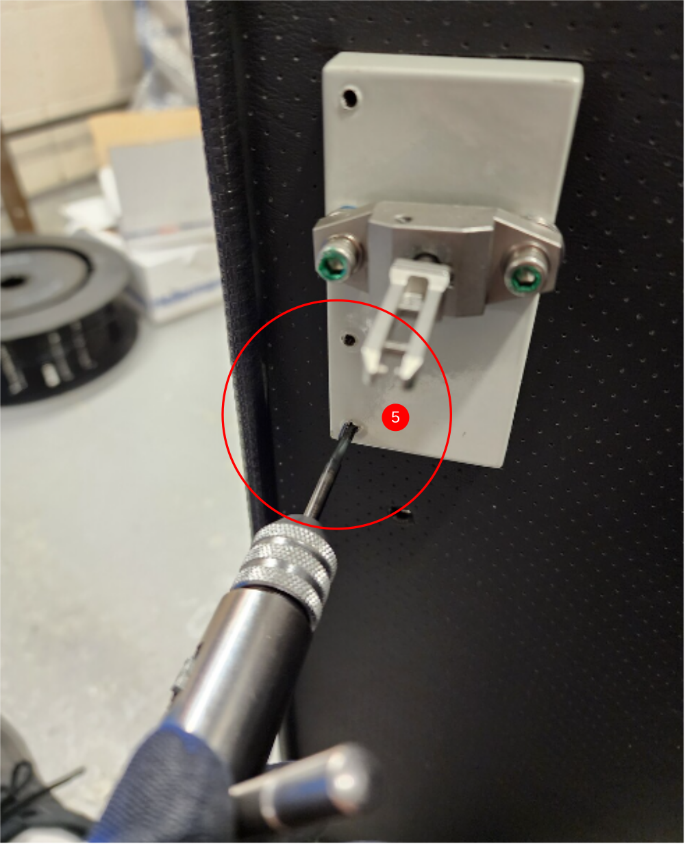
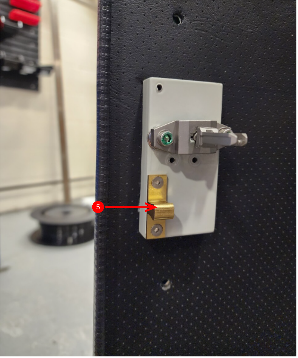
5 Tap holes to remove debris and Fit 1st part of door catch using 2 off M4 x 10 countersunk bolts
6 Fit Second part of catch as shown
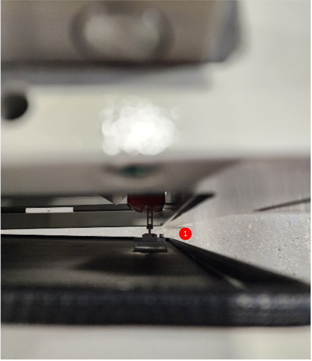
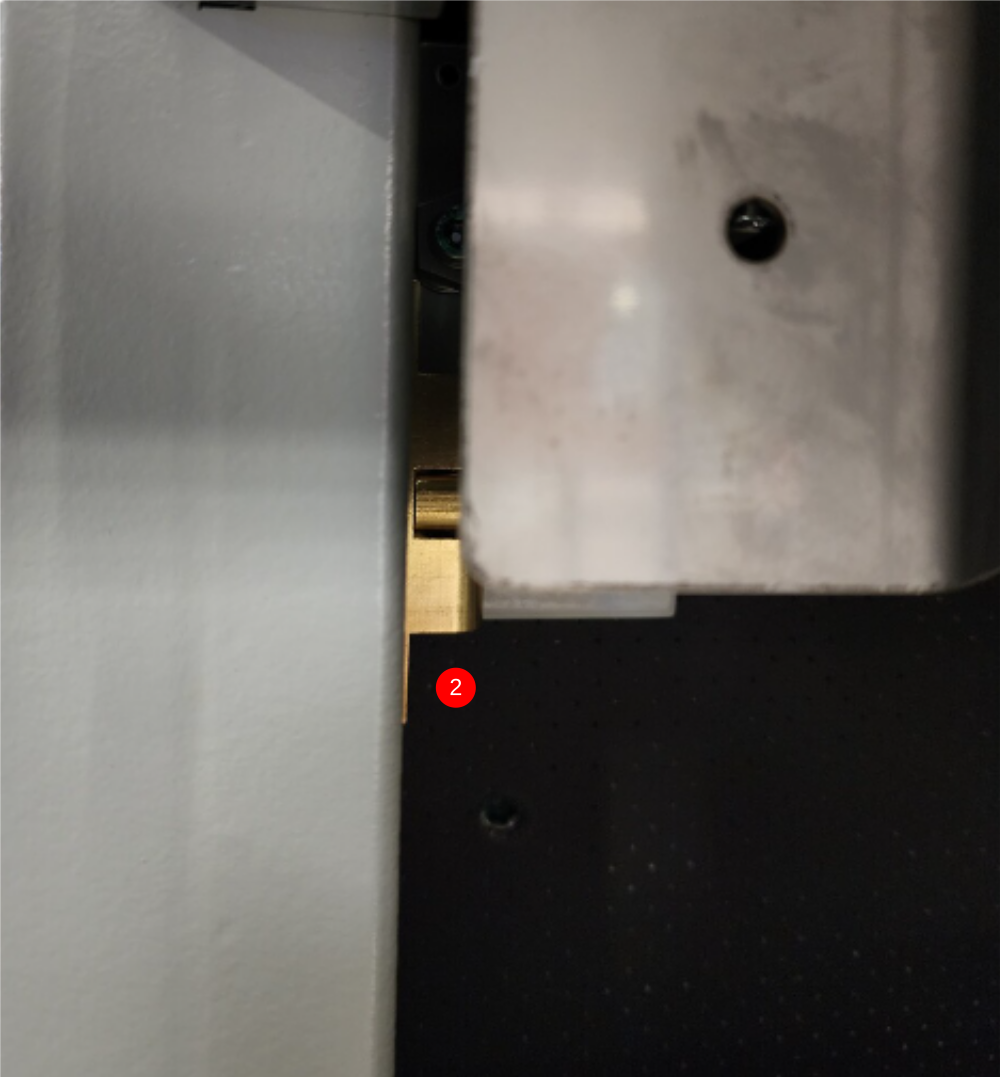
Étape 6 - Align interlock and drill Catch
1 Adjust interlock switch assembly to align exactly with fixed position of blade .
Entry of blade into switch must be smooth and perfectly aligned
2 Mark position of second part of catch assembly with door closed , and drill 2 off M4 tapped holes into frame . Fix with 2 off M4 x 10 countersunk fasteners
3 Check closing and opening of door once all components are fitted in correct and well aligned . Not excessive force should be needed to overcome latch assembly
Étape 7 - Fit serial plate
Attach pre stamped serial plate to hinge panel
Fix with rivets

Étape 8 - Fit hinge panel to frame

Étape 9 - Fit chute inserts
Fit 2 off chute inserts

Étape 10 - Fit rear chute
Fit rear chute

Étape 11 - Fit rear tray
Fit rear tray

Étape 12 - Fit front tray
Fit front tray

Étape 13 - Assemble and fit regulators
Assemble 3 off regulators and fit to panel
Add identification labels to regulators
Étape 14 - Fit top hood
Fit pre assembled top hood to frame

Étape 15 - Finalise position of tip strips
Finalise position of tip strips.
Please include correct setting for these parts
Étape 16 - Fit blade spanner
Fit blade spanner to frame

Étape 17 - Fit compliance guards
Fit front and side compliance guards

Draft
 Français
 English
 Deutsch
 Español
 Italiano
 Português