Process for alignment of infeed arms

Difficulté
Difficile
Durée
8 heure(s)
Sommaire
- 1 Introduction
- 2 Étape 1 - Unless otherwise stated
- 3 Étape 2 - Mount 1st section
- 4 Étape 3 - Mount 2nd section
- 5 Étape 4 - Mount 3rd section
- 6 Étape 5 - Quality Check
- 7 Étape 6 - Dowel sections in position
- 8 Étape 7 - Finalize fasteners
- 9 Étape 8 - Prepare Support Channels
- 10 Étape 9 - Mount Section
- 11 Étape 10 -
- 12 Étape 11 -
- 13 Commentaires
Introduction
Tools Required
Étape 1 - Unless otherwise stated
Use loctite 243 on all fasteners
Use Loctite 572 on all threaded pneumatic connections
Pen mark all bolts to show finalised

Étape 2 - Mount 1st section
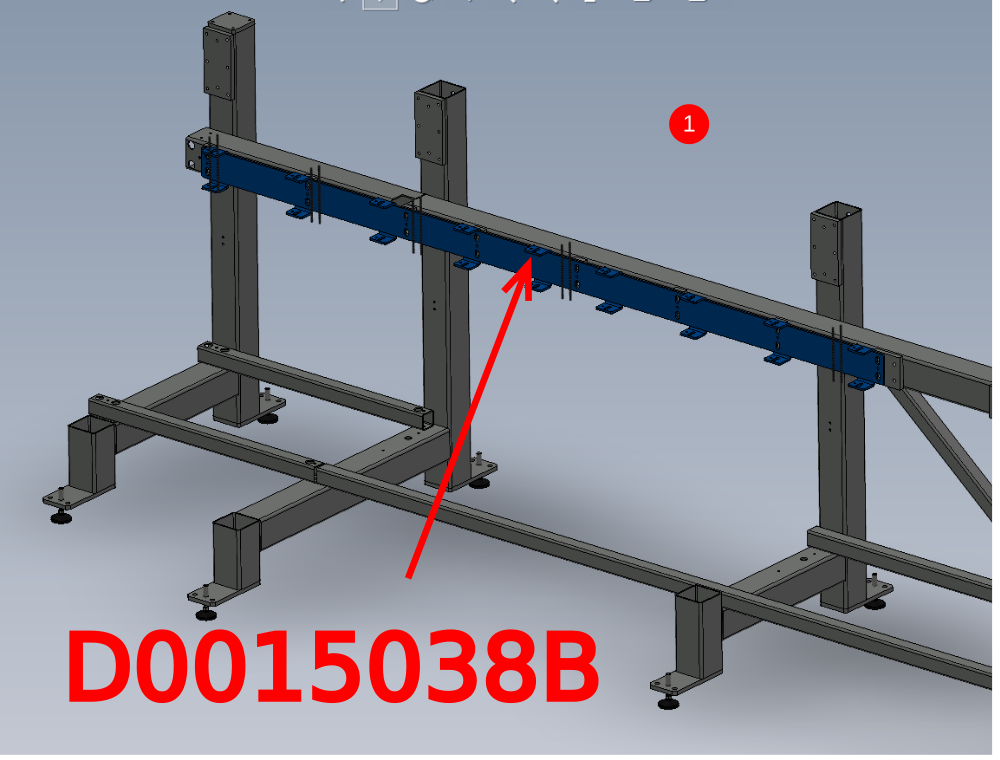
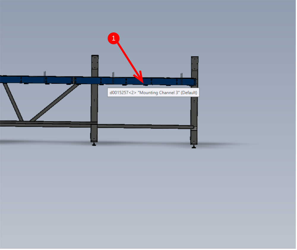
1 Mount D0015038B in position shown .
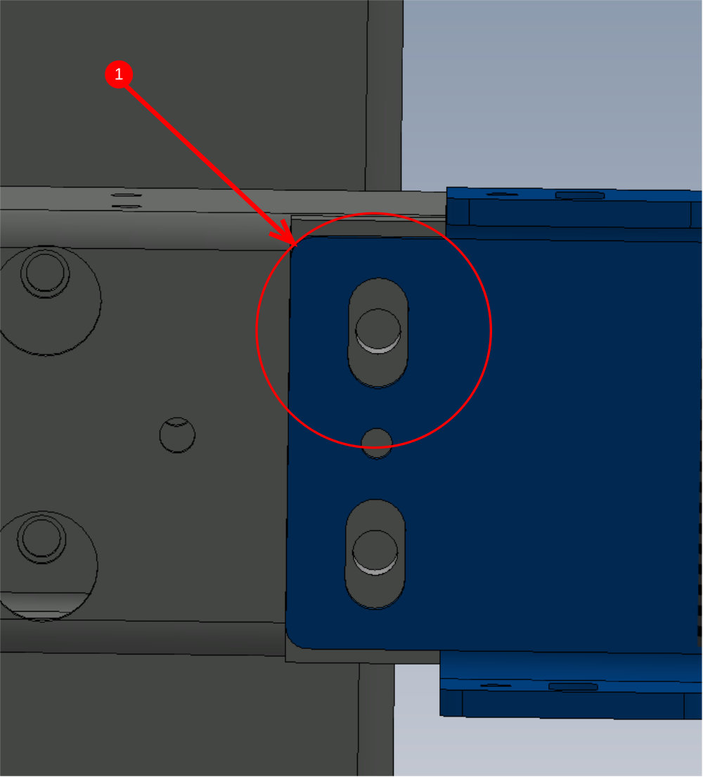
Use M12 x 25 set bolts and M12 A form washers. Do not add loctite 243 at this stage. Ensure Section is mounted mid slot as shown
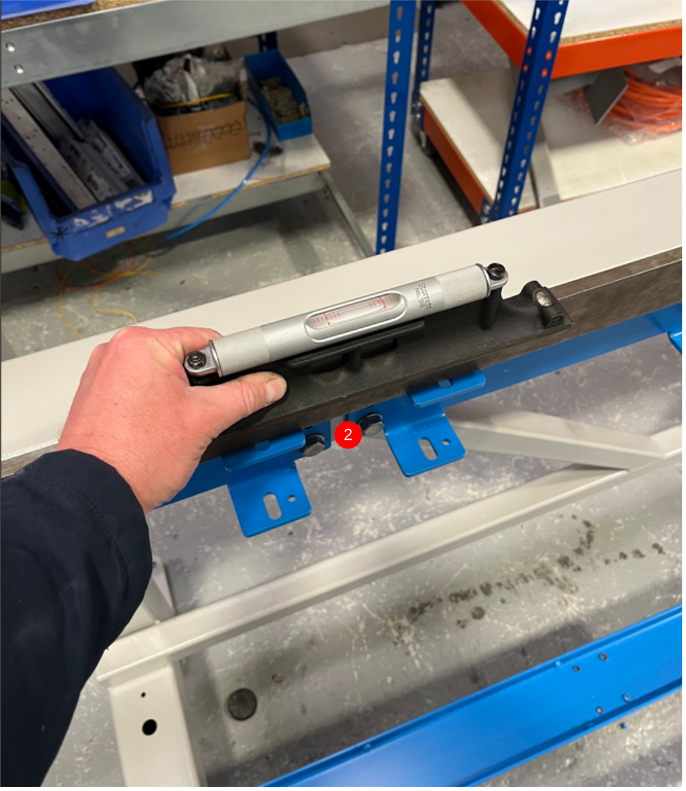
2 Use a 2 meter straight edge and position on top of mounted section as shown
Use 300mm engineers level and adjust indicated point to bring section level
3 Tension fasteners to hold support section position
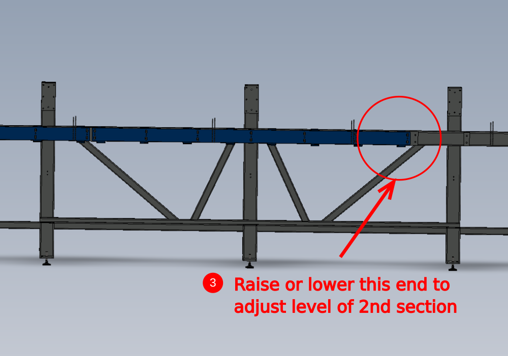
Étape 3 - Mount 2nd section
1 Mount D0015039B at position shown using same fixings as previous step
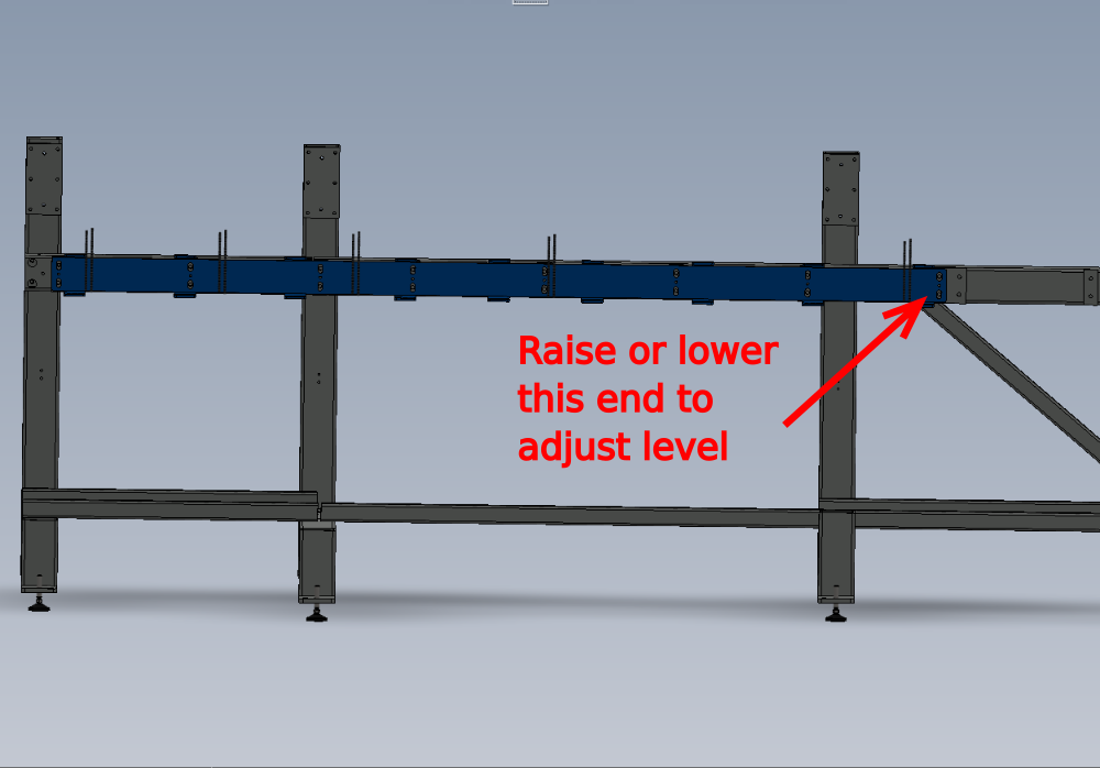
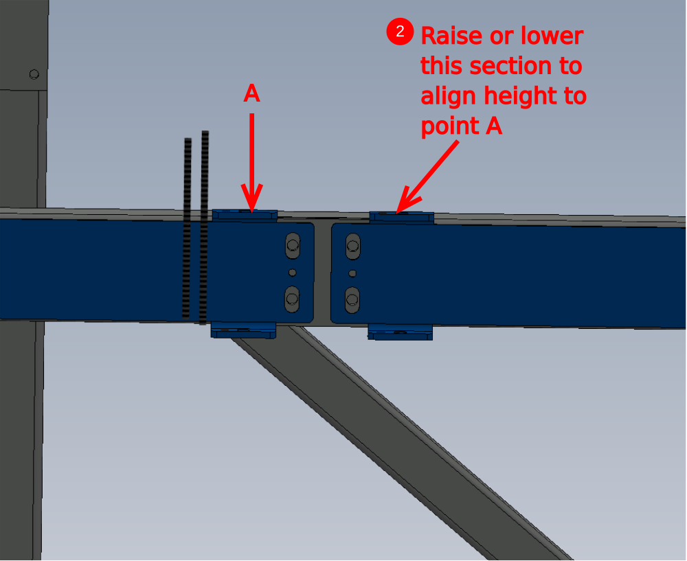
2 By extending 2 meter straight edge slightly from previous fitted section, set height at point shown to be flush with 1st section
3 Move straight edge to sit only on 2nd section and move indicated point to adjust level
4 Tension fasteners to hold support section position
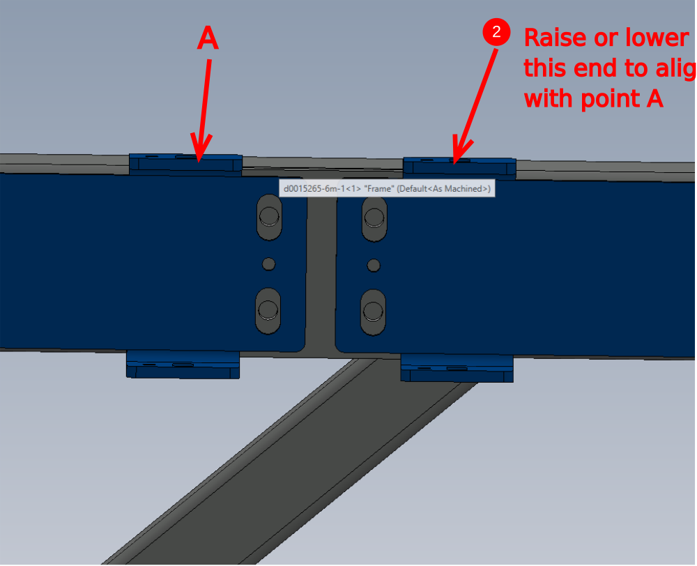
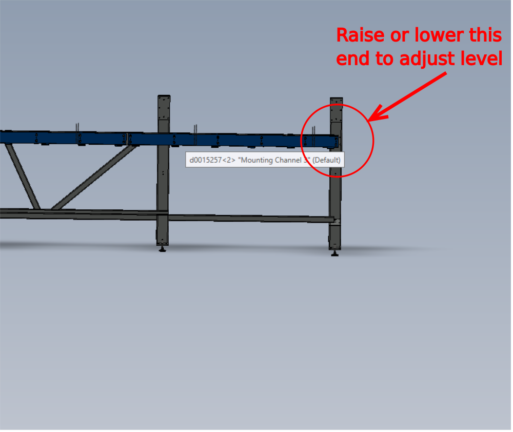
Étape 4 - Mount 3rd section
1 Mount D0015257 at position shown using same fixings as previous
2 By extending 2 meter straight edge slightly from previous fitted section, set height at point shown to be flush with 1st section
3 Move straight edge to sit only on 2nd section and move indicated point to adjust level
4 Tension fasteners to hold support section position
Étape 5 - Quality Check
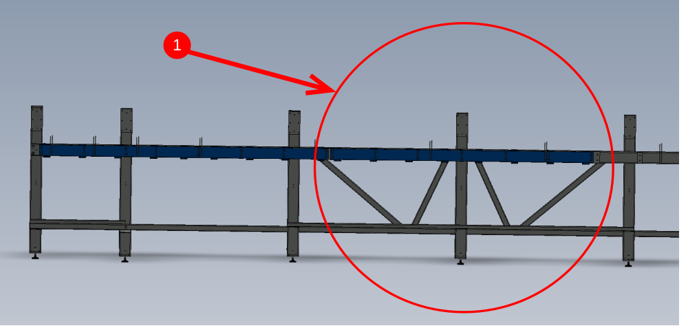
If the frame has been leveled accurately, the last section mounted should still be approximately mid slot when leveled
If there is not enough adjustment available at this point to level section, it indicates an error on frame leveling.
Supervisor check required at this point to confirm adjustments
Étape 6 - Dowel sections in position
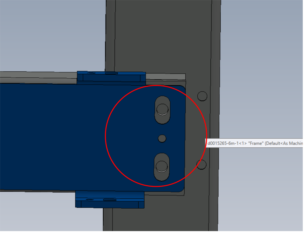
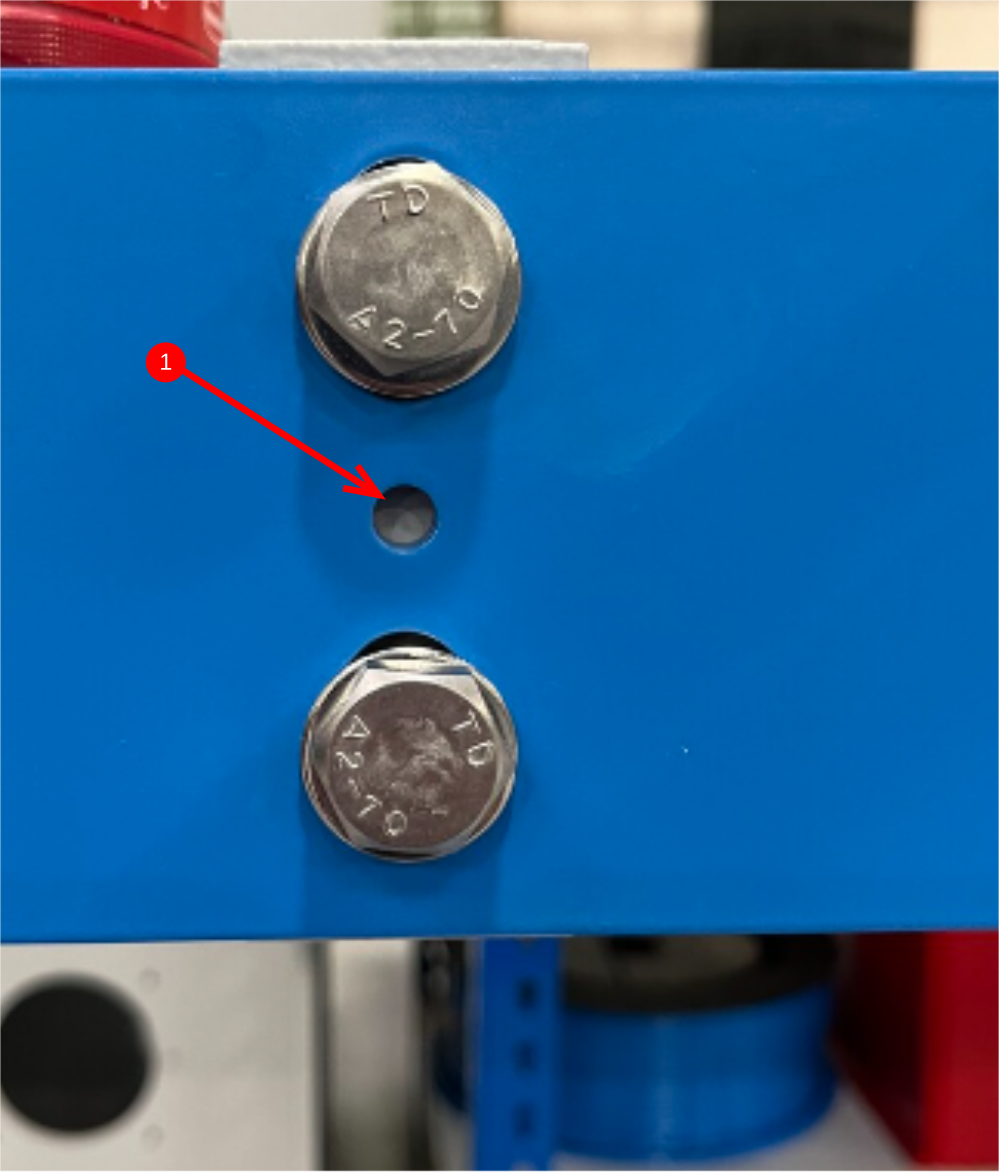
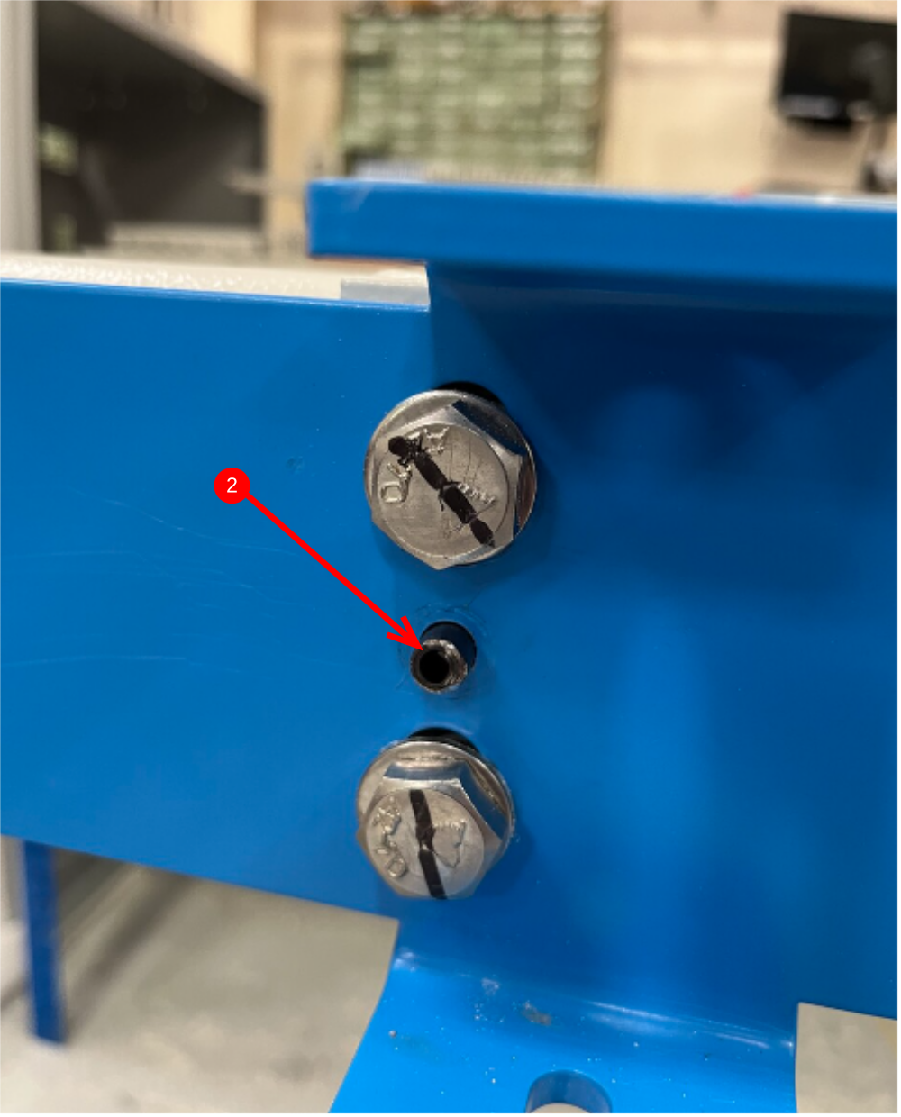
1 3 off mounted sections now require drilling for dowel pins
2 Drill hole 7mm , then increase to 8mm and then fit 8mm x 24mm spirol pin
3 Repeat this on all dowel positions on all 3 mounted sections
Étape 7 - Finalize fasteners
1 Remove M12 x 25 set bolt
2 Add Loctite 243 to thread
3 Refit and add final tension
4 Mark bolt as complete
5 Repeat for all M12 fasteners

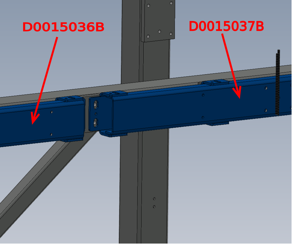
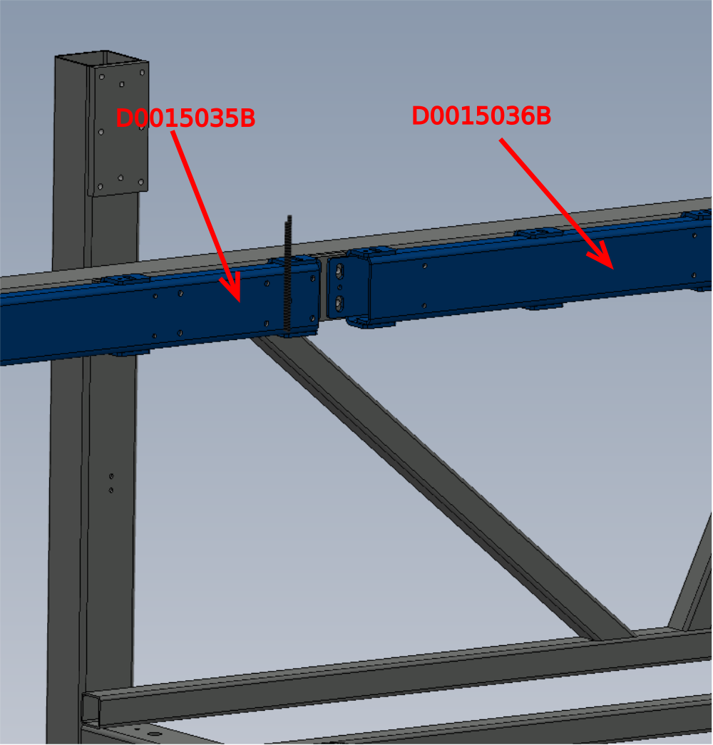
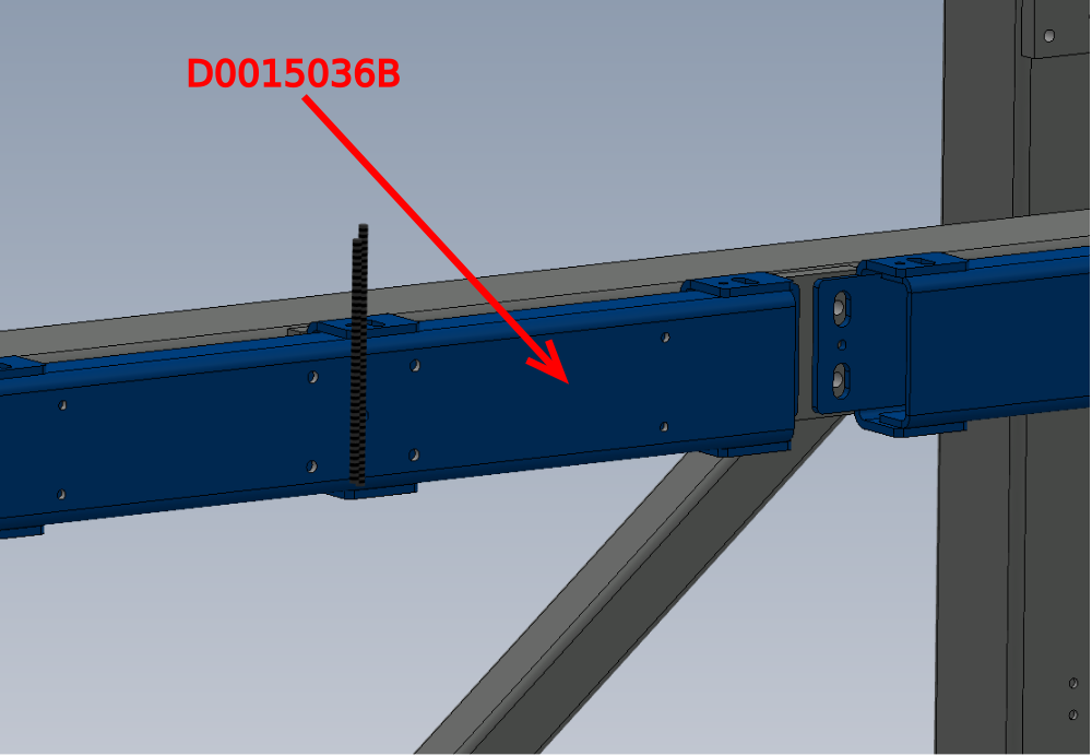
Étape 8 - Prepare Support Channels
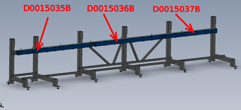
Prepare D0015035B,D0015036B and D0015037B ready for fitting.
All tapped holes require cleaning to remove any debris from coating process


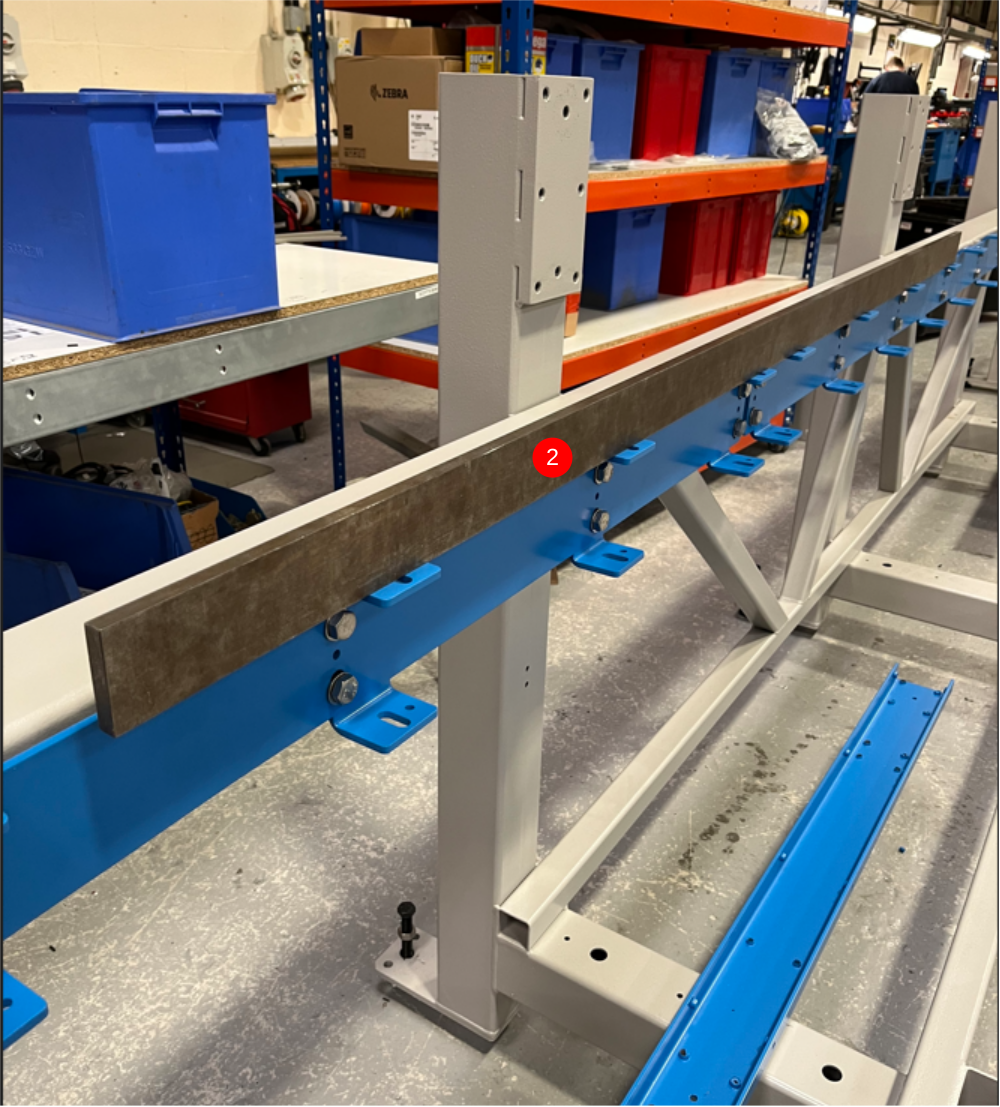
Étape 9 - Mount Section
1 Mount D0015035B as shown
2 Mount D0015036B as shown
3 Mount D0015037B as shown
4 Ensure when mounted, Middle slot position is obtained
5 Do not use Loctite 243 at this point


Étape 10 -
Étape 11 -
Draft
 Français
 English
 Deutsch
 Español
 Italiano
 Português