| [version en cours de rédaction] | [version en cours de rédaction] |
| Ligne 5 : | Ligne 5 : | ||
|Categories=Production | |Categories=Production | ||
|Difficulty=Medium | |Difficulty=Medium | ||
| − | |Duration= | + | |Duration=2 |
|Duration-type=hour(s) | |Duration-type=hour(s) | ||
}} | }} | ||
Version actuelle datée du 3 avril 2024 à 12:22
Bench assembly instructions for pneumatics rail

Difficulté
Moyen
Durée
2 heure(s)
Sommaire
- 1 Introduction
- 2 Étape 1 - Unless otherwise stated
- 3 Étape 2 - Handing
- 4 Étape 3 - Assemble valve 1
- 5 Étape 4 - Assemble valve bank 1
- 6 Étape 5 - Assemble valve bank 2
- 7 Étape 6 - Assemble Connection box
- 8 Étape 7 - Fix ethercat boxes to mounting plates
- 9 Étape 8 - Attach trunking
- 10 Étape 9 - Attach assemblies
- 11 Étape 10 - Fit connecting 12mm Blue pipework
- 12 Étape 11 - Secure Ethercat identification markers
- 13 Commentaires
Introduction
Tools Required
Standard hex key set
Standard spanner set
Pipe cutters
Standard HSS drill set
Step cutting drill
Standard screwdriver set
Parts Required
D0010167 x 3
C0001018 x 3
D0016300 x 1
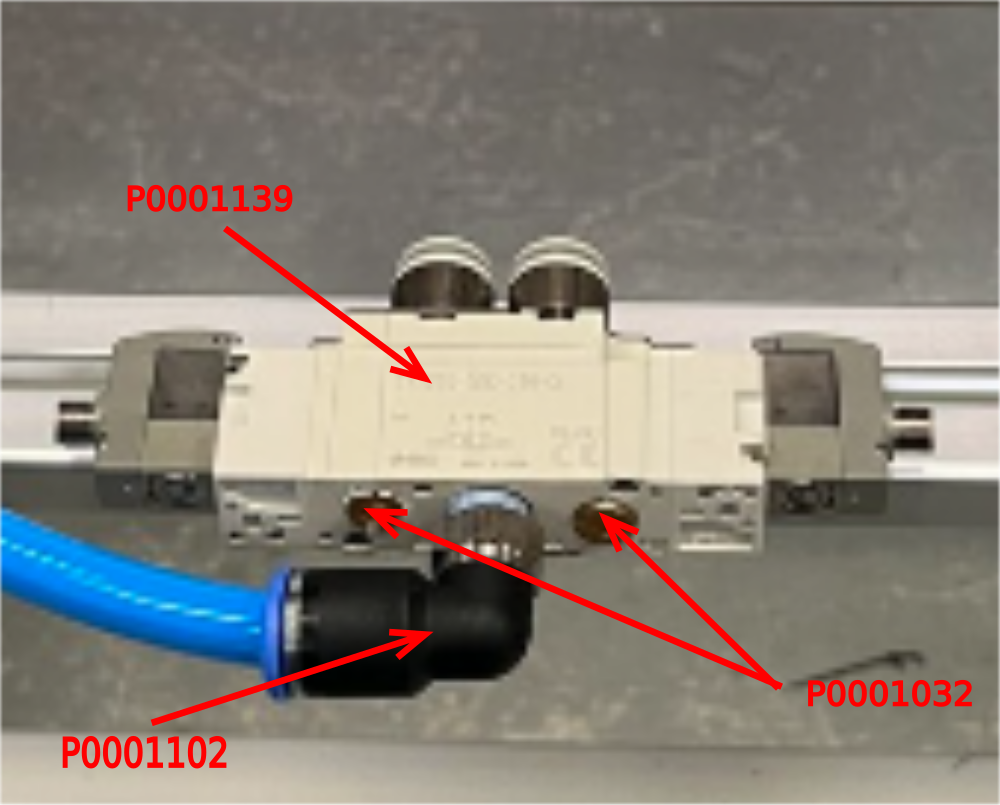
P0001139 x 1
P0001102 x 2
P0001032 x 2
P0001068 x 1
P0001101 x 3
P0001163 x 8
P0001071 x 1
P0001186 x 10
P0001151 x 1
A0000240 x 1
P0000159 x 5Étape 1 - Unless otherwise stated
Use Loctite 243 on all fasteners
Use Loctite 572 on all pneumatic threaded connections
Pen mark all fasteners to show finalised

Étape 2 - Handing
Assemble as shown for R to L machine
Mirror assembly for L to R machine
Étape 3 - Assemble valve 1
Attach Fitting P0001102 to valve P0001139 as shown . Add 2 off P0001032 silencers as indicated
Étape 4 - Assemble valve bank 1
Assemble valve bank 1 as shown using
P0001068 valve base x 1
P0001186 valve x 2
P0001101 fitting x 2
P0001163 fitting x 4

Étape 5 - Assemble valve bank 2
Assemble valve bank 2 as shown using
P0001071 valve base x 1
P0001186 valve x 8
P0001101 fitting x 1
P0001102 fitting x 1
P0001163 x 4
P0000159 x 4 ( information required for which ports to blank)

Étape 6 - Assemble Connection box
Connection box A0000240 will require holes adding to use.
Drill 2 off 5mm holes on back face to allow mounting on rail as shown. Use M4 socket caps and washers
Drill top face to mount A0000105 gland and fix with A0000255 nut

Étape 7 - Fix ethercat boxes to mounting plates
Mount ether cat boxes C0001018 to mounting plates D0010167 using m3 x 20 panhead bolts

Étape 8 - Attach trunking
Attach a length of 75mm x 25mm trunking @ 1310mm, 120mm from non slotted end to rear of maytec and use M5 x 6 button sockets to secure
Ecr raised to add holes to maytec section on 05/09/23
Holes will required drilling until ecr finalises
1st m5 hole 130mm from non slotted hole end , then spaced at 250mm Drill and tap m5
Étape 9 - Attach assemblies
Attach built assemblies to mounting bar D0016300 as shown using the following fixings
Space as follows
1st ethercat box 100mm from end of maytec non slotted end, second ethercat box butted against 1st.
All other components should be spaced at 100mm except for Valve 1 and Valvebank 1 which are spaced at 150mm
Valve 1 uses bracket P0001151 to attach using M4 x 12 socket caps and A form washers
Valve bank 1 and 2 secured with M4 x 40 socket caps and M8 motor plate washers, spaced away from maytec rail with 2 M8 washers to enable valve to sit straight
Ethercat mount plates use m6 x 16 socket caps and a form washers
Connection box uses M4 x 12 socket caps and washers

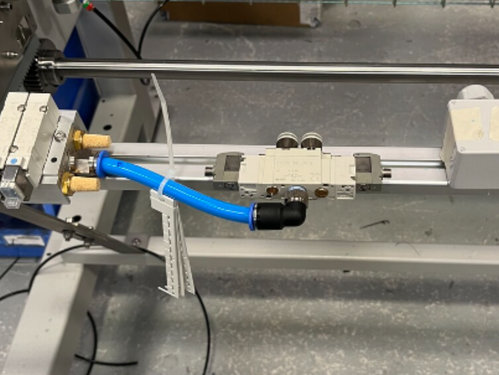
Étape 10 - Fit connecting 12mm Blue pipework
Connect as shown using 12mm blue air pipe


Étape 11 - Secure Ethercat identification markers
Make sure identification markers are safely stored with assembly ready for electrical terminations at a later point

Draft
 Français
 English
 Deutsch
 Español
 Italiano
 Português