| [version en cours de rédaction] | [version en cours de rédaction] |
| Ligne 31 : | Ligne 31 : | ||
D0015363 Sensor Flapper Support Transfer SEE NOTE x 1 | D0015363 Sensor Flapper Support Transfer SEE NOTE x 1 | ||
| − | |||
| − | |||
E0000336L Sensor: M8; 4mm, PNP N/O, M8 conn x 7 | E0000336L Sensor: M8; 4mm, PNP N/O, M8 conn x 7 | ||
Version du 27 septembre 2023 à 11:23
Bench assembly details for sensor rail

Difficulté
Moyen
Durée
2 heure(s)
Sommaire
- 1 Introduction
- 2 Étape 1 - Unless otherwise stated
- 3 Étape 2 - Quality check
- 4 Étape 3 - Assemble Maytec frame
- 5 Étape 4 - Fit bushes
- 6 Étape 5 - Fit 1st Pivot
- 7 Étape 6 - Add dowel
- 8 Étape 7 - Fit 1st plate
- 9 Étape 8 - Fit 2nd plate
- 10 Étape 9 - Repeat for remaining plates
- 11 Étape 10 - Fit sensors
- 12 Étape 11 - Fit tie bases
- 13 Étape 12 - Assemble and mount Ethercat box
- 14 Étape 13 - Fit support angles
- 15 Étape 14 - Quality check
- 16 Étape 15 - Electrical connections if requested
- 17 Commentaires
Introduction
Tools Required
Standard hex key set
Parts Required
B0001099 Bush flange 10 i/d 12 o/d x 14
C0001018 EP2338-0001 EtherCAT Box 8 Configurable IO x 1
D0010167 Ethercat Mount Plate x 1
D0015353 Sensor Flapper Pivot x 8
D0015355 Sensor Flapper Plate (312) x 6
D0015357 Sensor Flapper Plate (270) x 1
D0015363 Sensor Flapper Support Transfer SEE NOTE x 1
E0000336L Sensor: M8; 4mm, PNP N/O, M8 conn x 7
F0000537 dowel pin 10 x 40 x 8
M0001016 Angle 74 x 38 x 2
M0001209 Bracket m8 proximity sensor bracket 90 deg x 7
Étape 1 - Unless otherwise stated
Use Loctite 243 on all fasteners
Use Loctite 570 on all threaded pneumatic connections
Pen mark all bolts when finalised

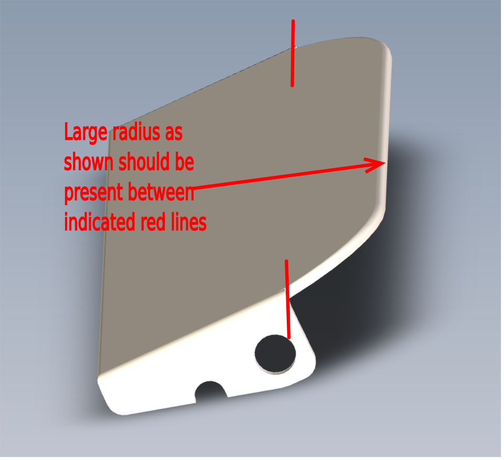
Étape 2 - Quality check
Check components
D0015355 Sensor Flapper Plate (312) x 6
D0015357 Sensor Flapper Plate (270) x 1
Ensure indicated have a radius on the indicated faces and are smooth and burr free
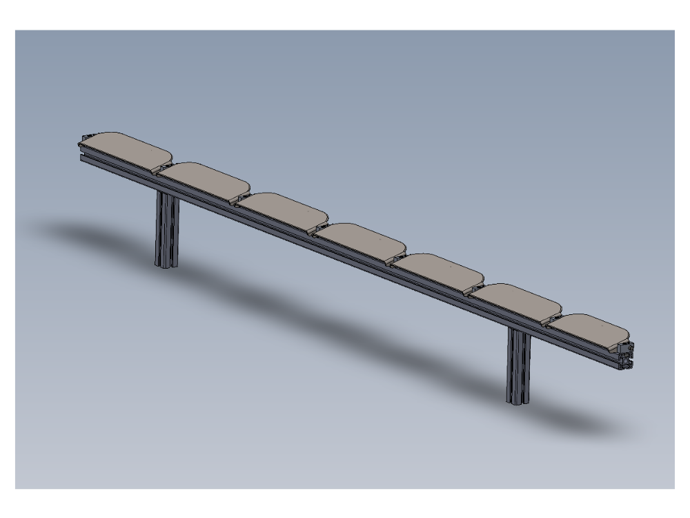
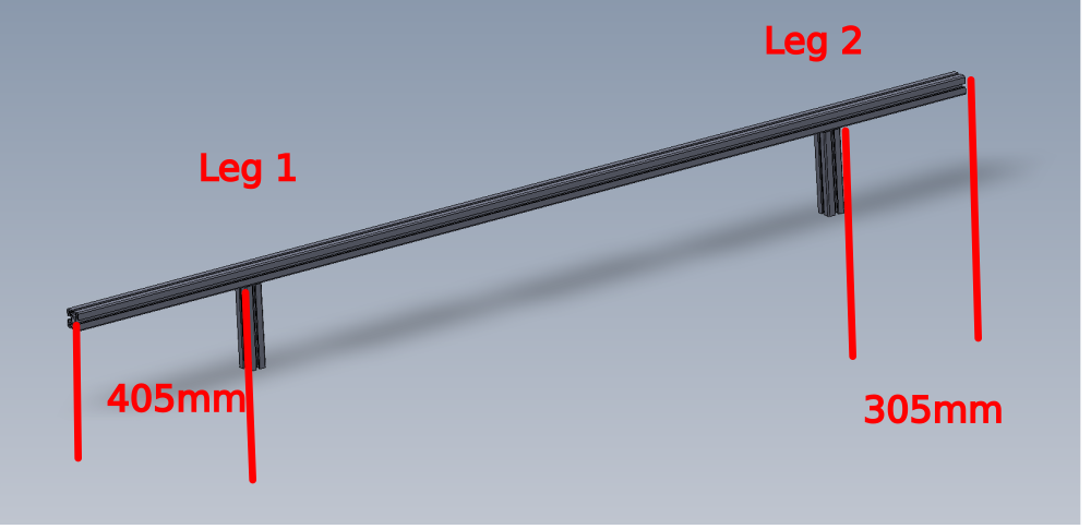
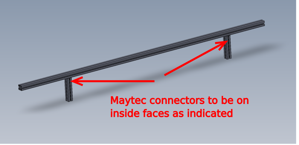
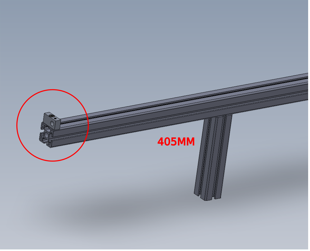
Étape 3 - Assemble Maytec frame
Assemble frame as shown
Set leg 1 to 405mm
Set leg 2 to 305mm


Étape 4 - Fit bushes
Fit B0001099 Bush flange 10 i/d 12 o/d x 14 into D0015355 Sensor Flapper Plate (312) x 6 and D0015357 Sensor Flapper Plate (270) x 1 as shown


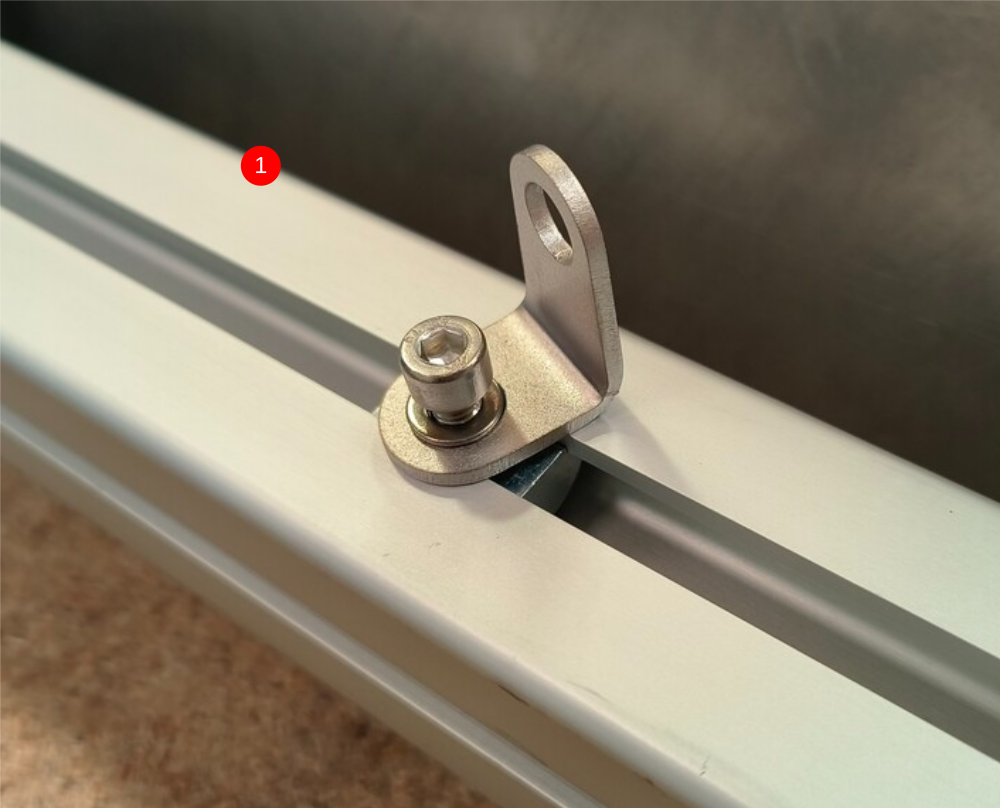
Étape 5 - Fit 1st Pivot
Fit 1st D0015353 Sensor Flapper Pivot as shown
Fix with F0000299 m6 d nut and M6 x 20 socket cap

Étape 6 - Add dowel
Fit F0000537 dowel pin 10 x 40 as shown, leaving 5mm of protrusion
Secure with M5 x 12 kcp grubscrew


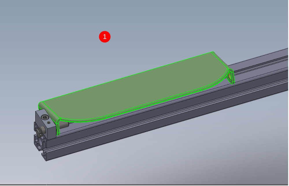
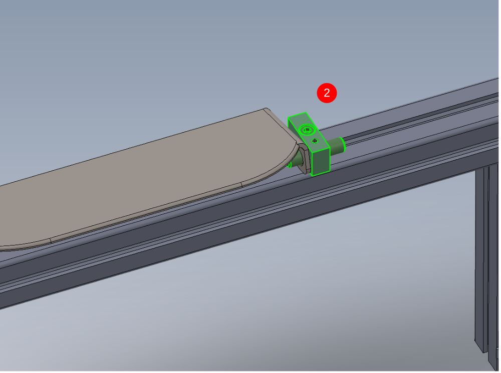
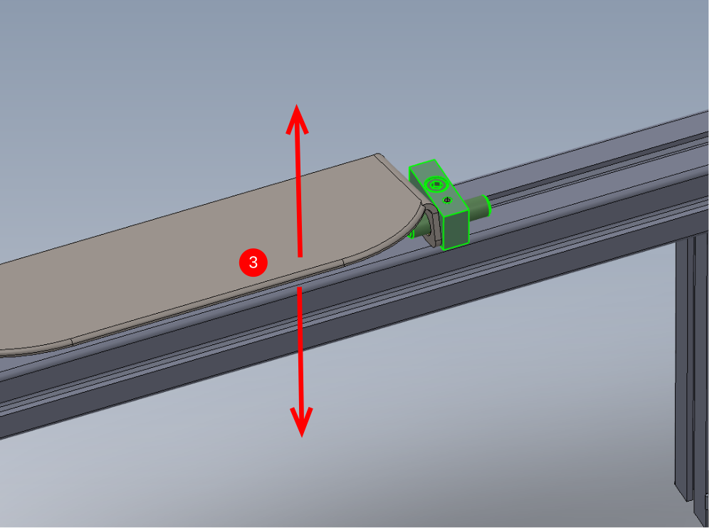
Étape 7 - Fit 1st plate
1 Position as shown D0015357 Sensor Flapper Plate
2 Captivate with pivot block and dowel as shown, using same fixings as previous pivot block . Ensure dowel sits central in pivot block.
3 Ensure sensor plate is free to move in the direction shown when fitted. Leave as minimal gap as possible between pivot blocks and sensor plate
Étape 8 - Fit 2nd plate
Fit D0015355 Sensor Flapper Plate (312) and fix with same method as previous steps

Étape 9 - Repeat for remaining plates
Fit remaining 5 plates in the same method as shown


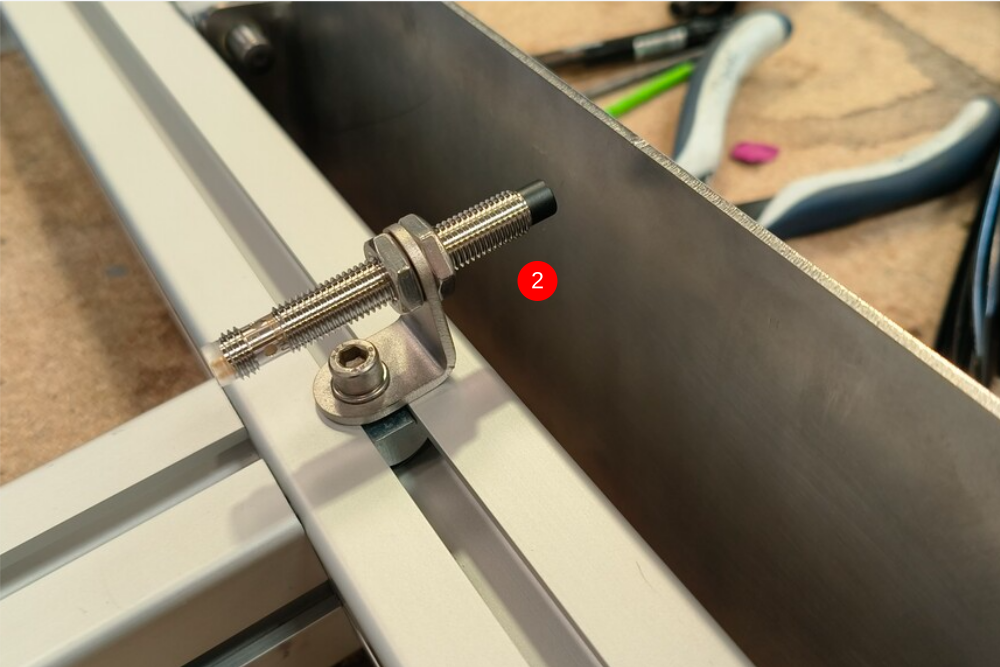
Étape 10 - Fit sensors
1 Fit 7 off M0001209 Bracket m8 proximity sensor bracket 90 deg. Position each bracket centrally beneath each sensor plate and orientate as shown
Use M5 fat D nut, M5 x 10 socket cap and A form washer to secure
2 Fit 7 off E0000336L Sensor: M8; 4mm, PNP N/O, M8 conn as shown .
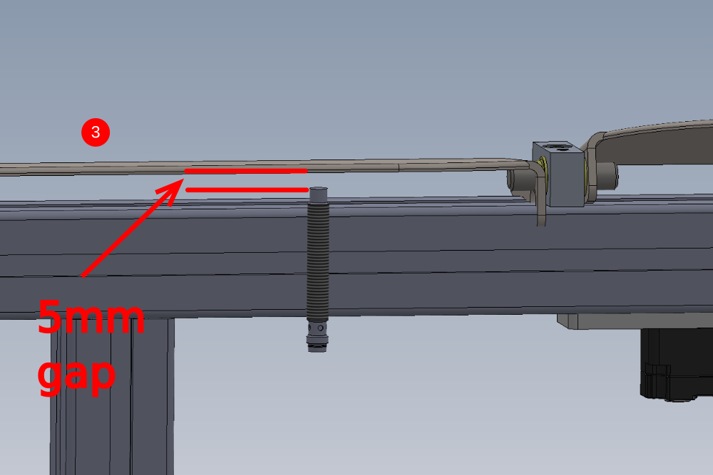
3 Set sensor gap to 5mm
With the sensor plate fully depressed in the direction shown, set sensor so 5mm gap is present
4 Secure 2 off lock nuts on sensor. Caution do not over tension, as this can lead to damage to sensor !
Étape 11 - Fit tie bases
Fit Cable tie bases using M5 x 10 button sockets an M5 fat D nuts at the positions shown
(cables shown are fitted at a later stage)


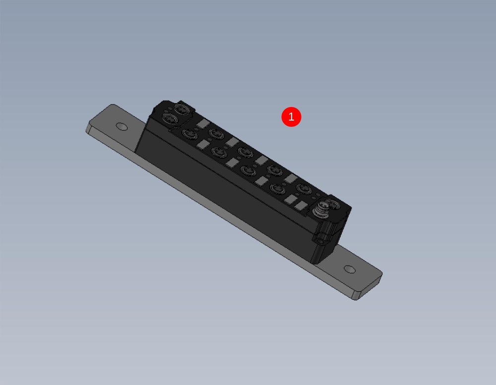
Étape 12 - Assemble and mount Ethercat box
1 Assemble C0001018 EP2338-0001 EtherCAT Box 8 Configurable IO onto D0010167 Ethercat Mount Plate x 1 as shown using M3 x 20 pan head fasteners
2 Fit to assembly Using 2 off M6 fat D nuts , M6 x 16 socket caps and A form washers at the position shown of 780 mm from indicated face to edge of ethercat box

Étape 13 - Fit support angles
Fit 2 off M0001016 Angle 74 x 38 as shown
Fasten with M8 Fat D nut, M8 x 20 socket cap and Heavy M8 motor plate washers

Étape 14 - Quality check
Ensure all fasteners are double checked for correct tension, adhesive and identification to show finalised

Étape 15 - Electrical connections if requested

Draft
 Français
 English
 Deutsch
 Español
 Italiano
 Português