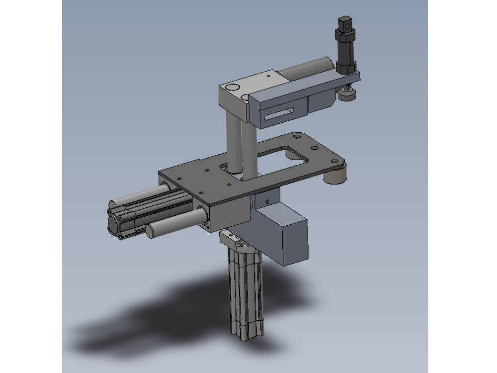
Instructions to bench assemble infeed clamp assembly

Difficulté
Moyen
Durée
2 heure(s)
Introduction
Tools Required
Standard hex key set
Standard spanner set
External circlip pliers
Grease for lubrication M0000494
Parts Required
B0000062 Circlip 20mm External x 2
B0000070 Linear Bearing: Ø25 x 40 Compact (Metal Case Only) x 8
B0001176 Washer :bearing shim x 3
D0000209 Shaft Strap (D8709) x 1
D0000211 Cylinder Extension x 1
D0001331 Roller Ø40 x 27 c/w bearing x 3
D0001334 Roller Ø40 x 102 c/w bearing x 2
D0003108 Shaft 20mm: 146mm Clamp Roller Shaft x 2
D0003788 Z Roller Pin (40mm) x 3
D0007680 Infeed Rail x 1
D0007774 Top Roller Block x 1
D0007792 Z Roller Block (D8711) x 1
D0007793 Z Roller Plate (D8710) x 1
D0015427 MC Hold Clamp Bar x 1
D0015428 Top Clamp Block Ø30 15 x 1
H0007773 Shaft 25mm: 268mm ZX Infeed Clamp Top x 2
H0007791 Shaft 25mm :250mm ZX Infeed side x 2
P0000007 Straight Adaptor 6mm - 1/8 BSP tapered thread x 1
P0000200 Elbow Adaptor 6mm - M5 x 2
P0000484 Cylinder 32 x 100 stroke x 1
P0001160 Cylinder 32 x 70 stroke x 1
P0001198 Fitting: flow control 1/8 x 6mm elbow x 4
Étape 1 - Unless otherwise stated
Use locktite 243 on all fasteners
Use loctite 572 on all threaded pneumatic connection
Pen mark all fasteners to show finalised

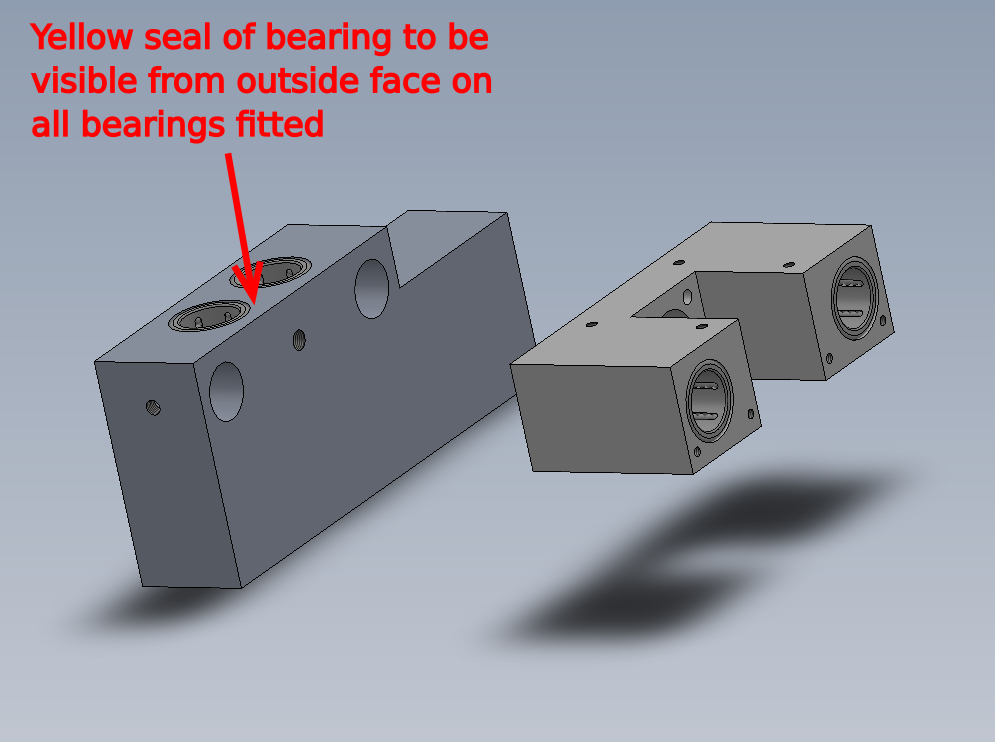
Étape 2 - Fit bearings
Fit 8 off B0000070 bearings to D0007680 Infeed Rail and D0007792 Z Roller Block (D8711) as shown
Ensure yellow part of bearing is always facing outside edge when fitted
Thoroughly grease bearings with M0000494 lubricant once fitted, ensuring all ball chambers are filled with grease

Étape 3 - Fit shafts
Fit H0007791 Shaft 25mm :250mm ZX Infeed side x 2 as shown .
Use 2 off M8 x 12 K.C.P grubscrew to secure


Étape 4 - Fit z block
Slide on D0007792 Z Roller Block taken care not to damage bearing seals

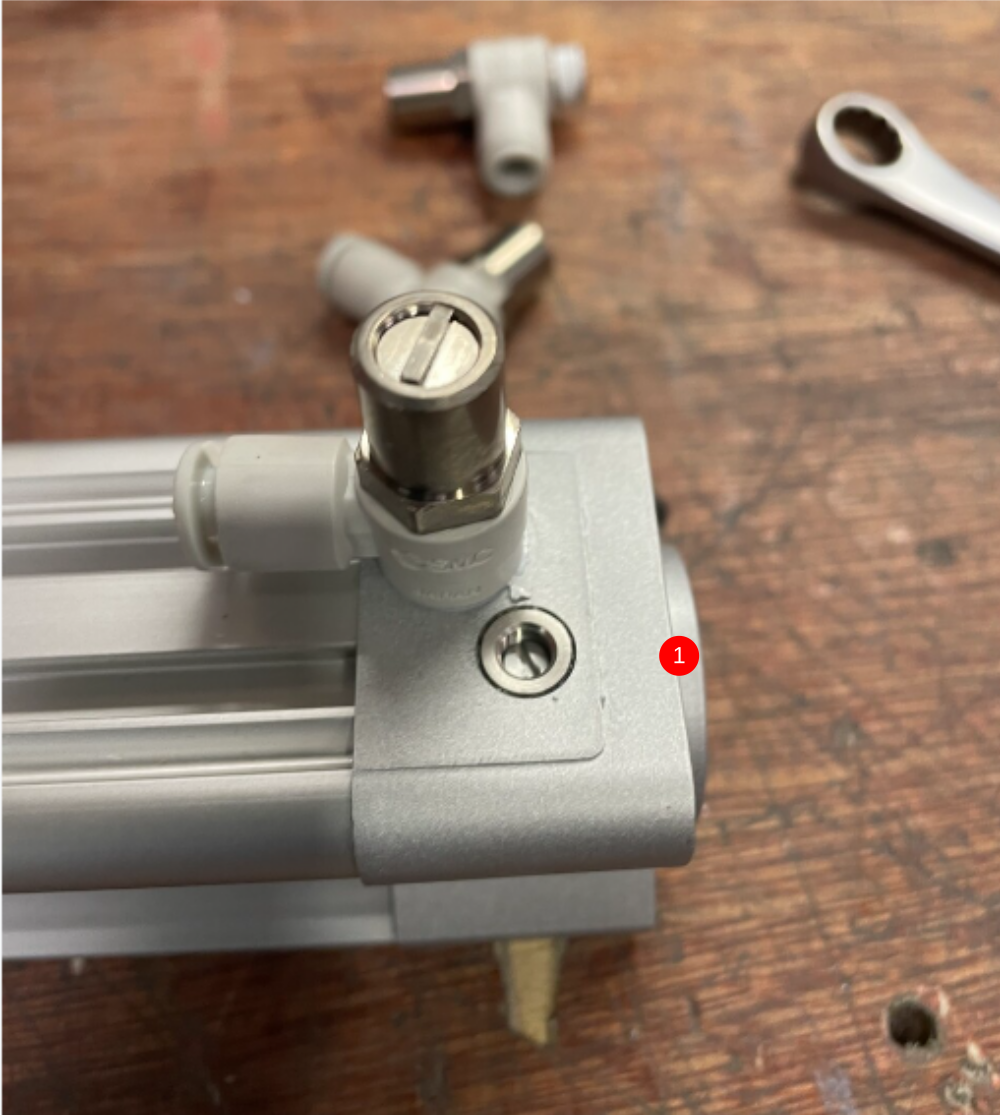
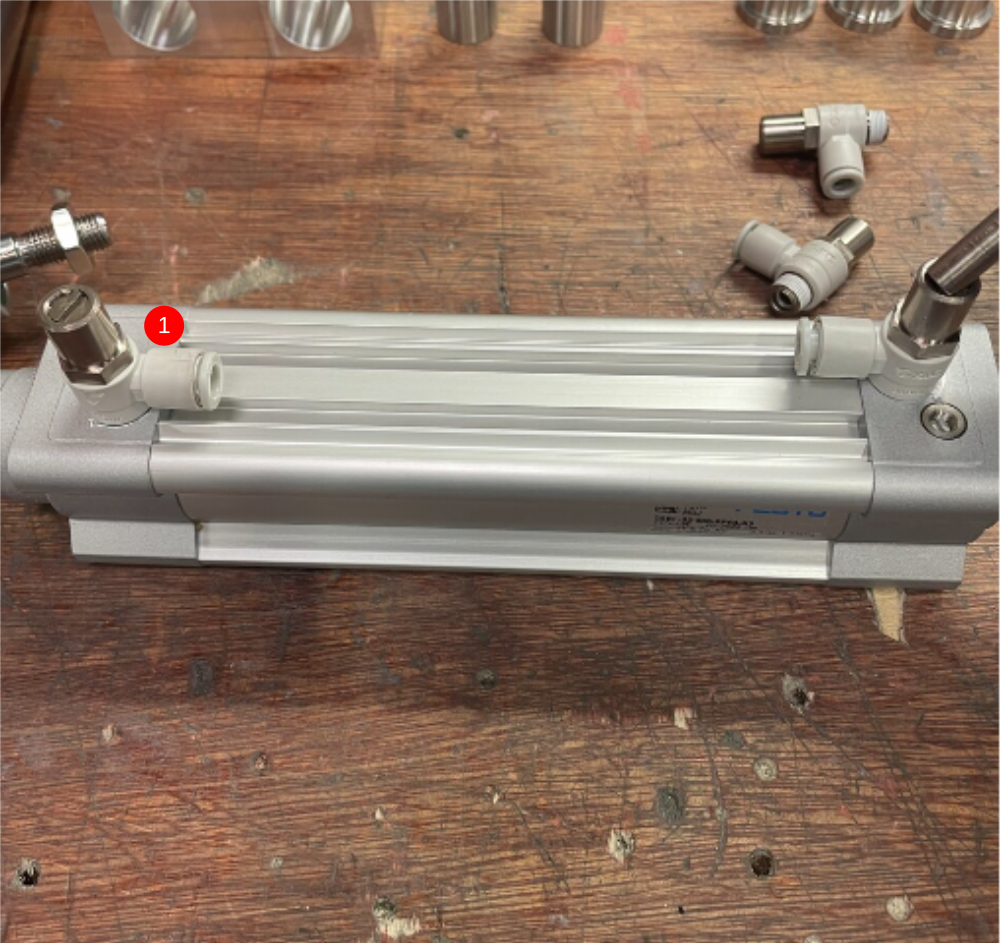
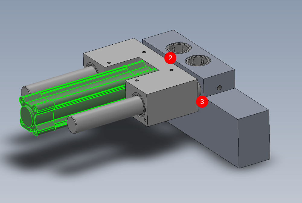
Étape 5 - Attach cylinder
1 Attach 2 off P0001198 Fitting: flow control 1/8 x 6mm elbow to cylinder P0000484 Cylinder 32 x 100 stroke
2 Attach cylinder to assembly using M6 x 35 socket caps and M6 A form washers (do not tension yet )
Find in cylinder piston to leave 2 threads exposed when lock nut is tightened
3 Push cylinder assembly to closed position (shown) and apply tension to M6 fixings
Finalise all bolts and nuts
4 Check alignment . Cylinder stroke should be even and smooth at all points of travel . There should be no tight spots, especially at the end points of cylinder travel
Draft
 Français
 English
 Deutsch
 Español
 Italiano
 Português