Instructions to bench assemble infeed clamp assembly

Difficulté
Moyen
Durée
3 heure(s)
Sommaire
- 1 Introduction
- 2 Étape 1 - Unless otherwise stated
- 3 Étape 2 - Fit bearings to main blocks
- 4 Étape 3 - Check fitment of the following rollers
- 5 Étape 4 - Check fit of shafts in bearings
- 6 Étape 5 - Degrease and bearing fit
- 7 Étape 6 - Fit shafts
- 8 Étape 7 - Fit z block
- 9 Étape 8 - Attach cylinder
- 10 Étape 9 - Fit z roller plate
- 11 Étape 10 - Mount low rollers
- 12 Étape 11 - Assemble top roller Block
- 13 Étape 12 - Attach shafts and mount
- 14 Étape 13 - Fit cylinder extension
- 15 Étape 14 - Attach shaft strap
- 16 Étape 15 - Attach cylinder
- 17 Étape 16 - Adjust alignment for correct operation
- 18 Étape 17 - Ensure correct position
- 19 Étape 18 - Assemble profile stop cylinder
- 20 Étape 19 - Attach to main assembly
- 21 Commentaires
Introduction
Tools Required
Standard hex key set
Standard spanner set
External circlip pliers
Grease for lubrication M0000494
Parts Required
B0000062 Circlip 20mm External x 2
B0000070 Linear Bearing: Ø25 x 40 Compact (Metal Case Only) x 8
B0001176 Washer :bearing shim x 3
D0000209 Shaft Strap (D8709) x 1
D0000211 Cylinder Extension x 1
D0001331 Roller Ø40 x 27 c/w bearing x 3
D0001334 Roller Ø40 x 102 c/w bearing x 2
D0003108 Shaft 20mm: 146mm Clamp Roller Shaft x 2
D0003788 Z Roller Pin (40mm) x 3
D0007680 Infeed Rail x 1
D0007774 Top Roller Block x 1
D0007792 Z Roller Block (D8711) x 1
D0007793 Z Roller Plate (D8710) x 1
D0015427 MC Hold Clamp Bar x 1
D0015428 Top Clamp Block Ø30 15 x 1
H0007773 Shaft 25mm: 268mm ZX Infeed Clamp Top x 2
H0007791 Shaft 25mm :250mm ZX Infeed side x 2
P0000007 Straight Adaptor 6mm - 1/8 BSP tapered thread x 1
P0000010 elbow 6mm 1/8 fitting x 1
P0000200 Elbow Adaptor 6mm - M5 x 2
P0000484 Cylinder 32 x 100 stroke x 1
P0001160 Cylinder 32 x 70 stroke x 1
P0001198 Fitting: flow control 1/8 x 6mm elbow x 4
M0000253 anti slip pad 22mm x 1
Étape 1 - Unless otherwise stated
Use locktite 243 on all fasteners
Use loctite 572 on all threaded pneumatic connection
Pen mark all fasteners to show finalised

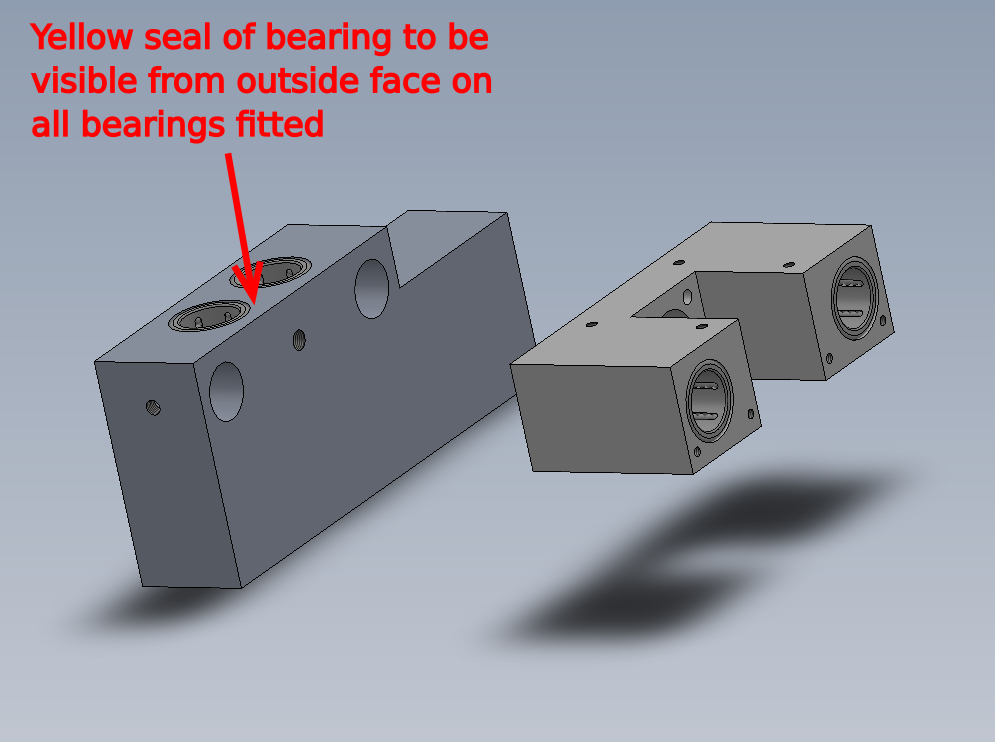
Étape 2 - Fit bearings to main blocks
Fit 8 off B0000070 bearings to D0007680 Infeed Rail and D0007792 Z Roller Block (D8711) as shown
Ensure yellow part of bearing is always facing outside edge when fitted
Thoroughly grease bearings with M0000494 lubricant once fitted, ensuring all ball chambers are filled with grease


Étape 3 - Check fitment of the following rollers
1 D0001331 Roller Ø40 x 27 c/w bearing and D0003788 Z Roller Pin (40mm)
2 D0001334 Roller Ø40 x 102 c/w bearing and D0003108 Shaft 20mm: 146mm Clamp Roller Shaft


Étape 4 - Check fit of shafts in bearings
Check fit of following parts .
Shafts should pass through bearings with only slight resistance . All inner bearing faces should have contact to shaft and rotate when the shaft is turned
If shafts are tight check drawing and inspect size of shaft .
If shaft slides through easily, then follow step 4

Étape 5 - Degrease and bearing fit
Thoroughly degrease all parts with FE10 solvent
1 Fit 20mm external circlip to shaft
2 Fit roller to shaft
3 Add 3 drops of Loctite 641 bearing retainer to indicated area and smear around the shaft
4 Move shaft to shown position and add 3 more drops of bearing fit to indicated face and smear around
5 Position roller against circlip and remove any excess bearing fit with rag
6 Leave roller in a vertical position to allow bearing fit to cure


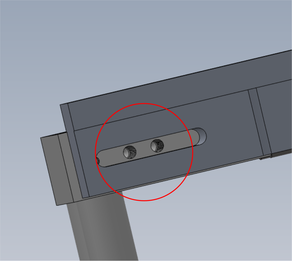
Étape 6 - Fit shafts
Fit H0007791 Shaft 25mm :250mm ZX Infeed side x 2 as shown .
Use 2 off M8 x 12 K.C.P grubscrew to secure


Étape 7 - Fit z block
Slide on D0007792 Z Roller Block taken care not to damage bearing seals

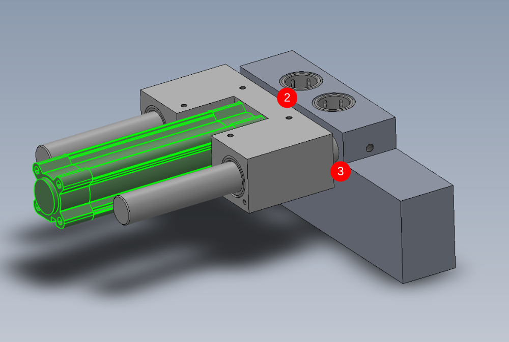
Étape 8 - Attach cylinder
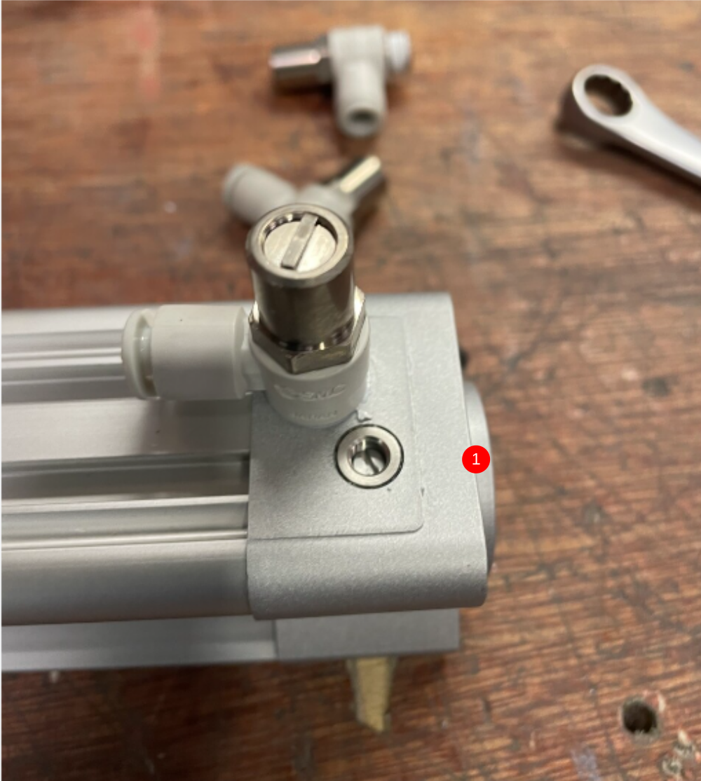
1 Attach 2 off P0001198 Fitting: flow control 1/8 x 6mm elbow to cylinder P0000484 Cylinder 32 x 100 stroke
2 Attach cylinder to assembly using M6 x 40 socket caps and M6 A form washers (do not tension yet )
Find in cylinder piston to leave 2 threads exposed when lock nut is tightened
3 Push cylinder assembly to closed position (shown) and apply tension to M6 fixings
Finalise all bolts and nuts
4 Check alignment . Cylinder stroke should be even and smooth at all points of travel . There should be no tight spots, especially at the end points of cylinder travel

Étape 9 - Fit z roller plate
Use 4 off M6 x 16 socket caps and A form washers to fit D0007793 Z Roller Plate

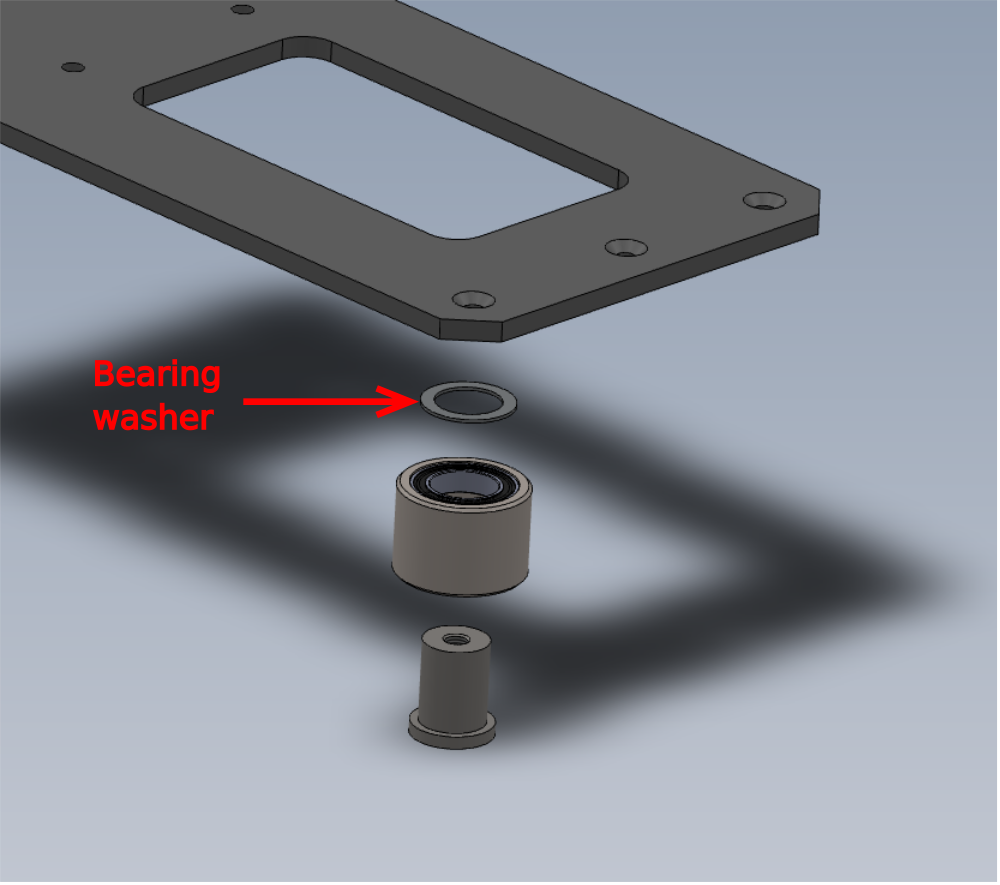
Étape 10 - Mount low rollers
Attach 3 off low rollers to z plate with M6 x 20 socket counter sunk fasteners
Ensure B0001176 Washer :bearing shim x 3 are positioned between each roller and z plate


Étape 11 - Assemble top roller Block
Attach pre built roller and shafts to D0007774 Top Roller Block using 2 off M6 x 10 KCP grubscrews


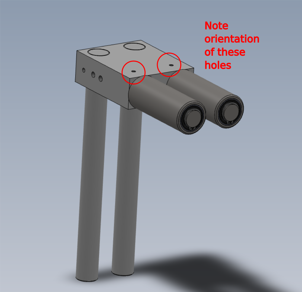
Étape 12 - Attach shafts and mount
1 Dry fit H0007773 Shaft 25mm: 268mm ZX Infeed Clamp Top x 2 using M6 x 10 KCP grubscrews
2 Fit to assembly , taking care to ensure bearing seals are not damaged when inserting shafts

Étape 13 - Fit cylinder extension
Fit D0000211 Cylinder Extension x 1 to hole shown . Finalise tension
Étape 14 - Attach shaft strap
Dry fit D0000209 Shaft Strap (D8709) using 2 off M6 x 25 socket caps

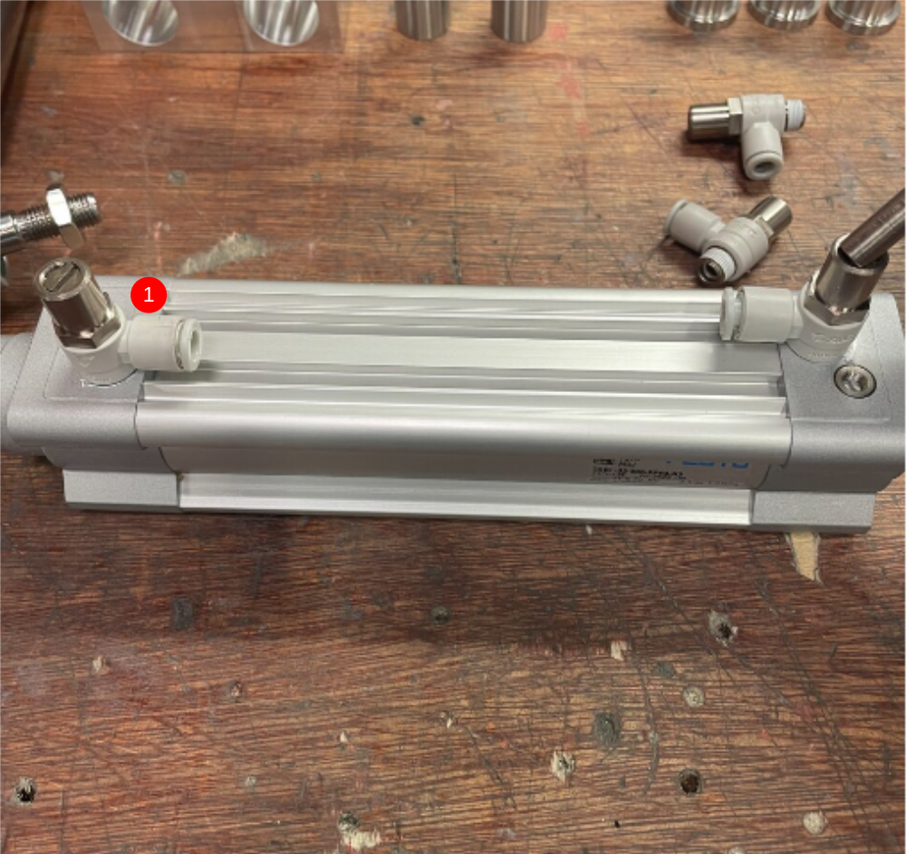
Étape 15 - Attach cylinder
Fit 2 0ff P00001198 air fittings to cylinder
Fit P0001160 cylinder 32 x 100 stroke in the orientation as shown
Finalise lock nut onto cylinder extension ,leaving two threads of cylinder thread exposed under lock nut. The access nut, release fixings for one shaft, slide upwards to create access to cylinder lock nut.
Dry fit cylinder to Shaft strap with 2 off M6 x 25 and 2 off M6 x 30 socket caps


Étape 16 - Adjust alignment for correct operation
Cylinder stroke must be smooth and consistent over full travel of cylinder . When rollers are lifted up, they should drop under their own weight to the lowest position.
Once alignment has been achieved, all fasteners should be individually removed and apply Loctite 243 and finalised
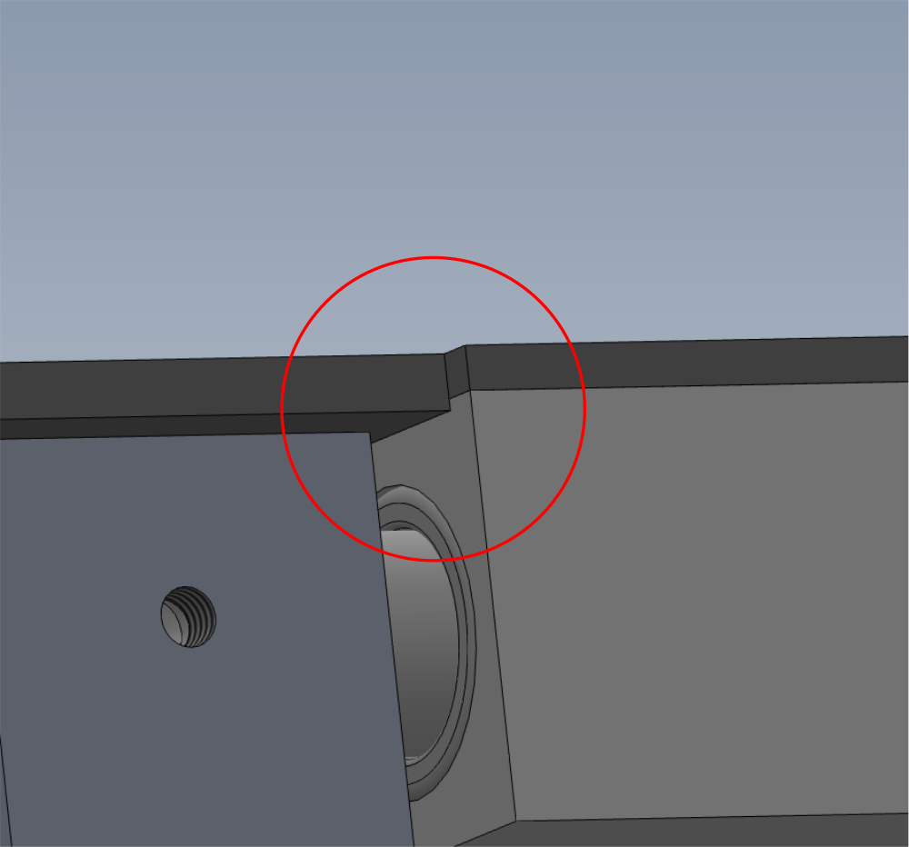
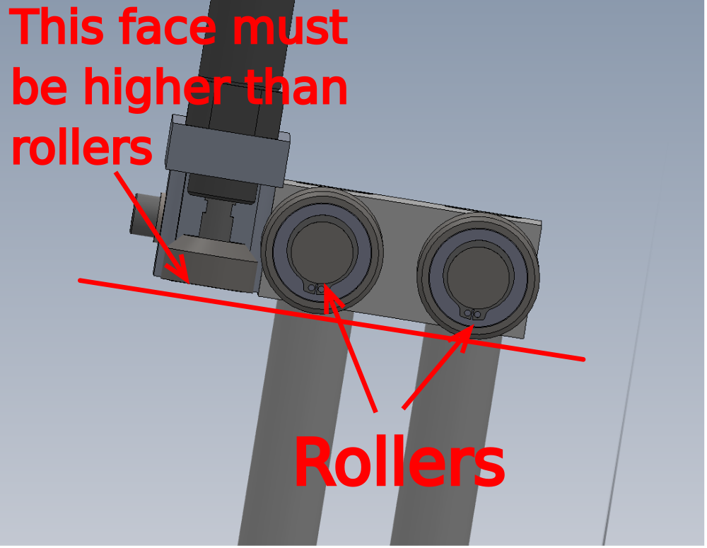
Étape 17 - Ensure correct position
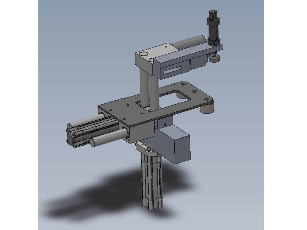
Ensure when fitting profile stop assembly as shown, that the indicated part sits above the rollers as shown
Vital for correct operation of clamp hold assembly

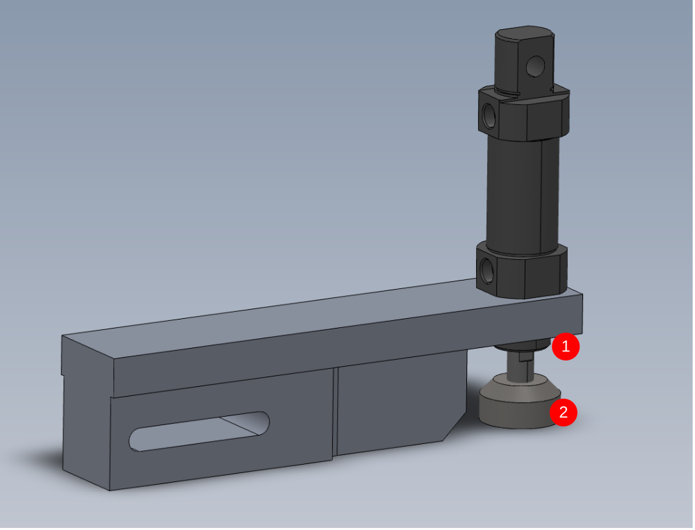
Étape 18 - Assemble profile stop cylinder
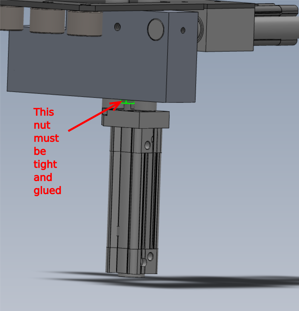
1 Use loctite 243 on cylinder fixing nut
2 D0015428 Top Clamp Block Ø30 15
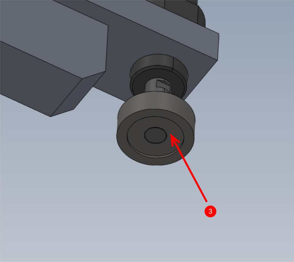
3 Fit M0000253 anti slip pad 22mm to indicated face
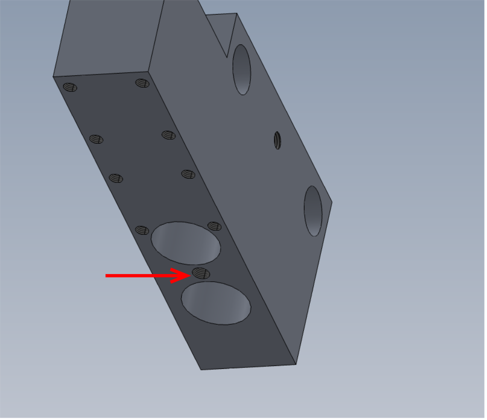
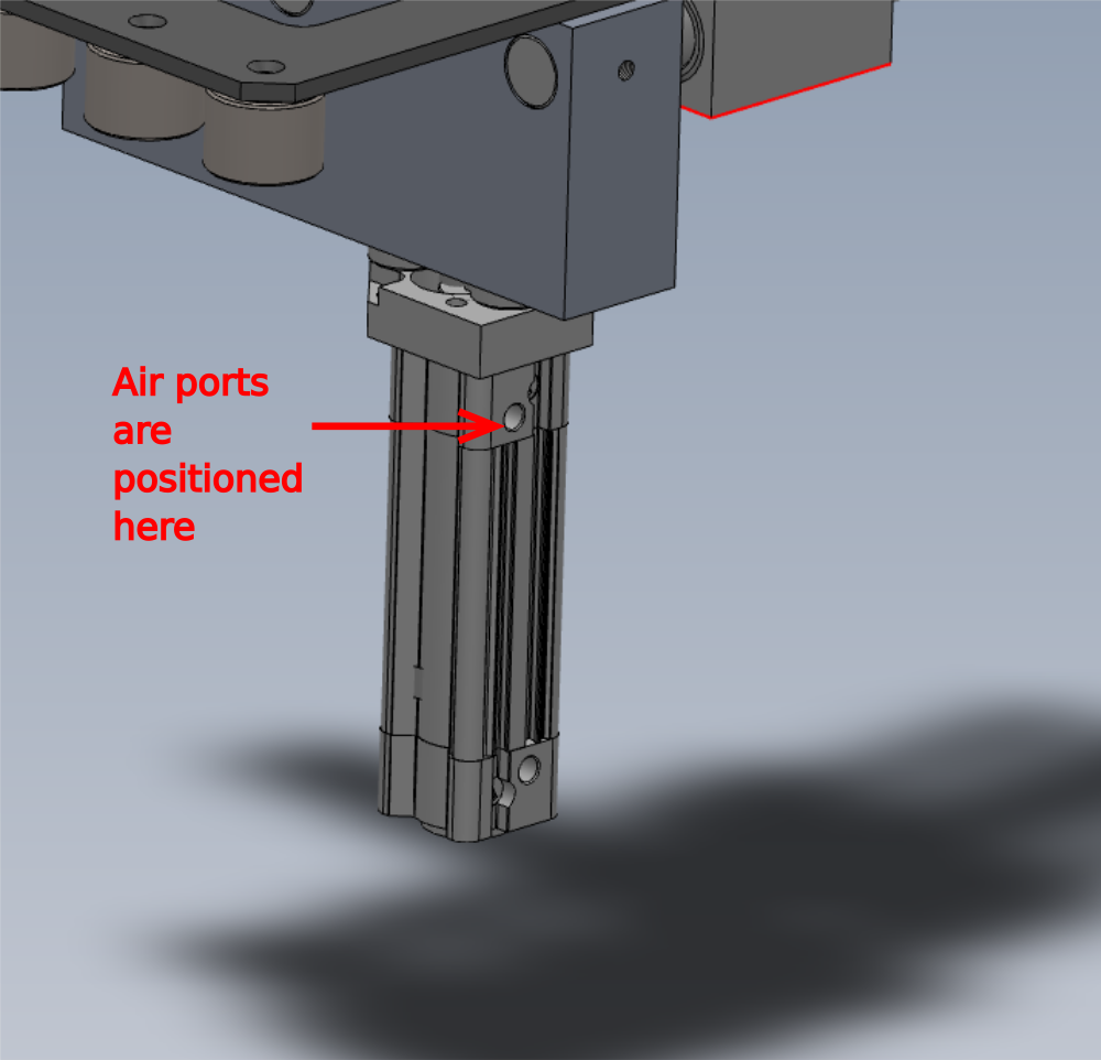
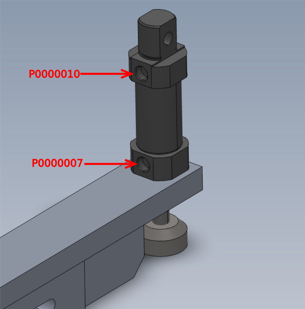
4 Fit P0000007 Straight Adaptor 6mm - 1/8 BSP tapered thread x 1 and P0000010 elbow 6mm 1/8 fitting x 1 to ports shown
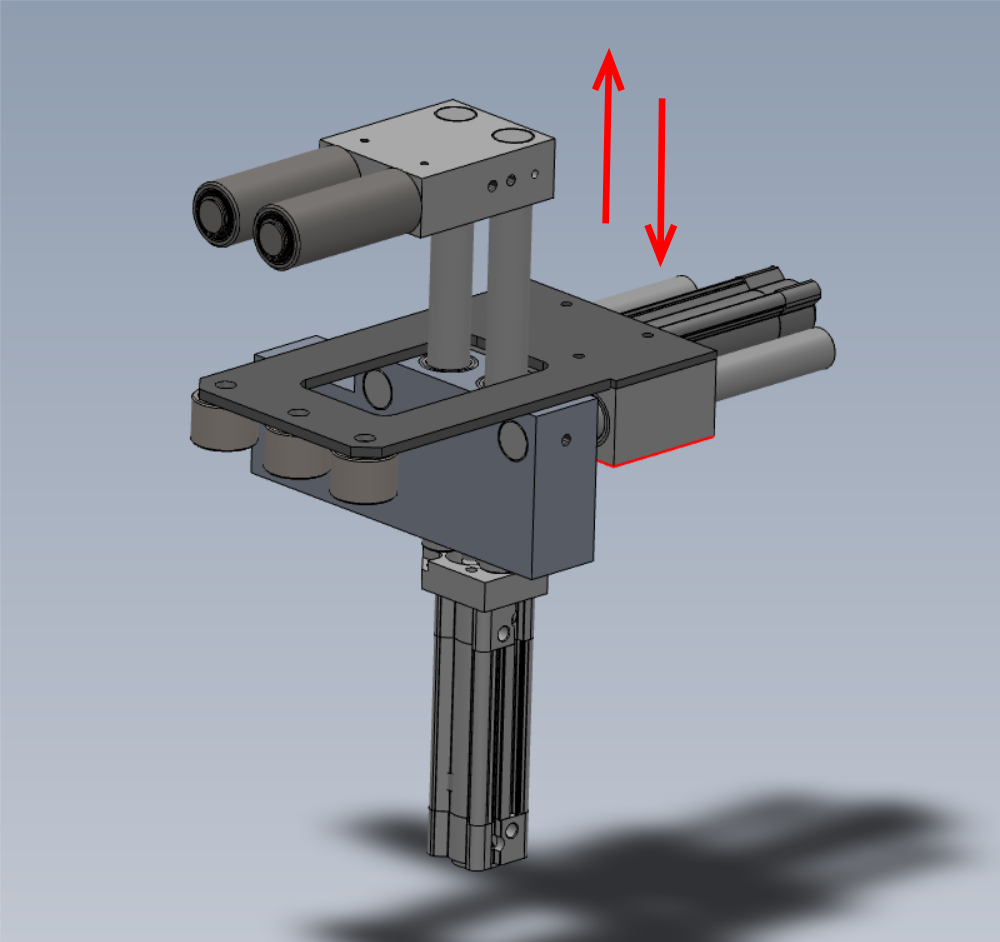
Étape 19 - Attach to main assembly
Attach cylinder stop to main assembly as shown using 2 off M8 x 50 socket caps and a form washers . Set to middle slot position

Draft
 Français
 English
 Deutsch
 Español
 Italiano
 Português