| [version en cours de rédaction] | [version en cours de rédaction] |
| Ligne 165 : | Ligne 165 : | ||
Provide drilling details for update</translate> | Provide drilling details for update</translate> | ||
|Step_Picture_00=R0015041_Bench_Assemble_Top_Hood_Assembly_Screenshot_2023-10-19_144222.png | |Step_Picture_00=R0015041_Bench_Assemble_Top_Hood_Assembly_Screenshot_2023-10-19_144222.png | ||
| + | }} | ||
| + | {{Tuto Step | ||
| + | |Step_Title=<translate>Fit connection box</translate> | ||
| + | |Step_Content=<translate>Fit abs connection box | ||
| + | |||
| + | |||
| + | Please provide drilling details for update</translate> | ||
| + | |Step_Picture_00=R0015041_Bench_Assemble_Top_Hood_Assembly_Screenshot_2023-10-19_153721.png | ||
}} | }} | ||
{{Tuto Step | {{Tuto Step | ||
| Ligne 222 : | Ligne 230 : | ||
Adjust 6mm pins to centralise flap and stop end float of assembly</translate> | Adjust 6mm pins to centralise flap and stop end float of assembly</translate> | ||
|Step_Picture_00=R0015041_Bench_Assemble_Top_Hood_Assembly_Screenshot_2023-10-19_143831.png | |Step_Picture_00=R0015041_Bench_Assemble_Top_Hood_Assembly_Screenshot_2023-10-19_143831.png | ||
| + | }} | ||
| + | {{Tuto Step | ||
| + | |Step_Title=<translate>Fit trunking to rear</translate> | ||
| + | |Step_Content=<translate>Fit A0001098 37mm x 75mm trunking to rear of hood | ||
| + | |||
| + | |||
| + | Provide drilling details for fixing</translate> | ||
| + | |Step_Picture_00=R0015041_Bench_Assemble_Top_Hood_Assembly_Screenshot_2023-10-19_153659.png | ||
}} | }} | ||
{{Tuto Step | {{Tuto Step | ||
Version du 19 octobre 2023 à 16:37
Bench assembly details for Saw top Hood

Difficulté
Moyen
Durée
6 heure(s)
Sommaire
- 1 Introduction
- 2 Étape 1 - Unless otherwise stated
- 3 Étape 2 - attach hinges to top door
- 4 Étape 3 - Fit top door to hood
- 5 Étape 4 - Fit door switch
- 6 Étape 5 - Attach gas strut
- 7 Étape 6 - Fit acoustic sound proofing
- 8 Étape 7 - Fit Rear emergency stop
- 9 Étape 8 - Fit light
- 10 Étape 9 - Fit Cable retentions
- 11 Étape 10 - Fit console mount bracket
- 12 Étape 11 - Fit connection box
- 13 Étape 12 - Fit beacon to top hood
- 14 Étape 13 - Mount camera
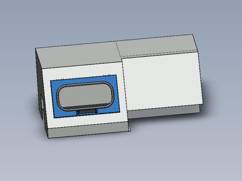
- 15 Étape 14 - Fit Top door screen
- 16 Étape 15 - Loom cables
- 17 Étape 16 - Assembly safety flap
- 18 Étape 17 - Fit safety flap to hood
- 19 Étape 18 - Fit trunking to rear
- 20 Étape 19 - Fit stickers to hood
- 21 Commentaires
Introduction
Tools Required
Standard hex key set
Standard spanner set
Standard Hss drill set
Standard tap set
Acoustic foam cutting board and straight edge
Utility Blade
Parts Required
Pre wired light, beacon and network cable from electrical department
C0001152 Camera: HikVision DS-2CD2343G0-I-2.8mm x 1
C0001239 Micro SD Card 32Gb Class 10 x 1
D0000770 Door Hinge (M0016) x 2
D0001877 Saw Top Door Mk4 x 1
D0004641 Hinge Pin Block (D7445) x 1
D0004642 Flap Counterbalance Bar x 1
D0004645 Safety Flap Hinge Pin x 1
D0004679 Flap Stiffening Bar x 1
D0004705 Flap Hinge Bar x 1
D0004747B top door screen x 1
D0004807 Flap x 1
D0007445 Hinge Pin Block OH (D4641) x 1
D0016251 Saw Hood Switch Mount Plate (Bernstein) x 1
E0000275 Button: Base Fixing 1 N/C x 1
E0001072 Emergency Stop Module Bevelled 1NO 1NC x 1
E0001569 Guard Lock Switch: Bernstein Radius Actuator (Key) x 1
H0004643 4mm Axxis Clear 145mm x 690mm x 1
M0000002 12mm Grey Acoustic Foam with Black PVC Facing x 1 (consumable stock )
M0000036 Sign - Ear Protection x 1
M0000048 Gas Spring 15mm x 100mm x 1
M0000539 Handle Black Nylon 200mm M8 Fixings x 1
Étape 1 - Unless otherwise stated
All bolts to have Loctite 243 adhesive applied unless otherwise stated
All Threaded Pneumatic connections to have Loctite 570 applied
All bolts to be pen marked once adhesive applied and correct tension added

Étape 2 - attach hinges to top door
Fix hinges to top hood
Mark hinge positions onto top door , set door even to aperture
Drill top door to allow fitment of hinges
Remove hinges from top hood and fit to top door
Attach handle to top door

Étape 3 - Fit top door to hood
Fit top door to hood

Étape 4 - Fit door switch
Mount interlock switch to mounting
Fit interlock blade to top door
ensure interlock is set to open position
Mark and drill correct position of interlock assembly onto hood

Étape 5 - Attach gas strut
Attach gas strut to top door assembly and set correct gas pressure
Door must hold up under own weight but not open violently

Étape 6 - Fit acoustic sound proofing
Fit acoustic foam to top hood

Étape 7 - Fit Rear emergency stop
Drill and fit rear emergency stop module
Please provide drilling details to enable update of part drawing

Étape 8 - Fit light
Fit light to inside of hood

Étape 9 - Fit Cable retentions
Drill and fit cable tie bases on hood
Please capture and add details here to allow drawing to be updated to reflect holes added
Étape 10 - Fit console mount bracket
Fit console mount bracket to top hood
Provide drilling details for update

Étape 11 - Fit connection box
Fit abs connection box
Please provide drilling details for update

Étape 12 - Fit beacon to top hood
Fit beacon to top hood
Any drilling details add here
Étape 13 - Mount camera
Drill and fit camera to top hood
Supply drilling details to capture data to update please
Étape 14 - Fit Top door screen
Fit top door screen to top door
Fit rim cord M0000031 to top door
Étape 15 - Loom cables
Loom cables to rear lower area of top hood

Étape 16 - Assembly safety flap
Ream 6mm to ensure pins locate correctly
Drill flap to suit stiffening bar
Attach end brackets
Insert 6mm rods and grubscrews
fit hazard tape to flap

Étape 17 - Fit safety flap to hood
Fit 1 off mounting block to centre point
Fit 2nd block to safety flap and fit to hood
Adjust 6mm pins to centralise flap and stop end float of assembly

Étape 18 - Fit trunking to rear
Fit A0001098 37mm x 75mm trunking to rear of hood
Provide drilling details for fixing

Étape 19 - Fit stickers to hood
Fit stickers to hood
Make sure to include ear defender sticker, logo stickers top and rear and ambient and consumable stickers

Draft
 Français
 English
 Deutsch
 Español
 Italiano
 Português