| [version en cours de rédaction] | [version en cours de rédaction] |
| Ligne 190 : | Ligne 190 : | ||
|Step_Picture_04=R0015038_Bench_Assemble_V_notch_Datum_Rollers_Screenshot_2023-07-19_112316.png | |Step_Picture_04=R0015038_Bench_Assemble_V_notch_Datum_Rollers_Screenshot_2023-07-19_112316.png | ||
|Step_Picture_05=R0015038_Bench_Assemble_V_notch_Datum_Rollers_Screenshot_2023-07-19_112322.png | |Step_Picture_05=R0015038_Bench_Assemble_V_notch_Datum_Rollers_Screenshot_2023-07-19_112322.png | ||
| + | }} | ||
| + | {{Tuto Step | ||
| + | |Step_Title=<translate>Caution</translate> | ||
| + | |Step_Content=<translate>It is vital that shaft dimples are correctly aligned for Fixing grubscrews to locate properly | ||
| + | |||
| + | |||
| + | To check correct alignment | ||
| + | |||
| + | |||
| + | Insert shaft and visually align dimple through grub screw hole | ||
| + | |||
| + | Insert grub screw and fasten | ||
| + | |||
| + | Wind grub screw out 1/2 turn | ||
| + | |||
| + | Shaft should be able to move slightly , but not be retracted from bore. | ||
| + | |||
| + | |||
| + | This will confirm grubscrew and dimple are correctly aligned</translate> | ||
| + | |Step_Picture_00=R0015338_Bench_Assemble_Serial_Plate_caution.png | ||
| + | |Step_Picture_01=R0008013_Clacker_assembly_quality.png | ||
}} | }} | ||
{{Tuto Step | {{Tuto Step | ||
Version actuelle datée du 28 mars 2024 à 17:41
Instructions to bench assemble v notch datum rollers

Difficulté
Moyen
Durée
2 heure(s)
Sommaire
- 1 Introduction
- 2 Étape 1 - Unless otherwise stated
- 3 Étape 2 - Assemble maytec frame
- 4 Étape 3 - Bearing fitment
- 5 Étape 4 - Warning
- 6 Étape 5 - Fit bearings to low rollers
- 7 Étape 6 - Fit bearings to long rollers
- 8 Étape 7 - Check fit of shafts in bearings
- 9 Étape 8 - Degrease and bearing fit
- 10 Étape 9 - Caution
- 11 Étape 10 - Add circlip and fit roller
- 12 Étape 11 - Mount rollers
- 13 Étape 12 - Quality check rollers and position
- 14 Étape 13 - Mount Cut tables
- 15 Commentaires
Introduction
Tools Required
Standard Hex key set
External circlip pliers
1 meter straight edge
Feeler gauges
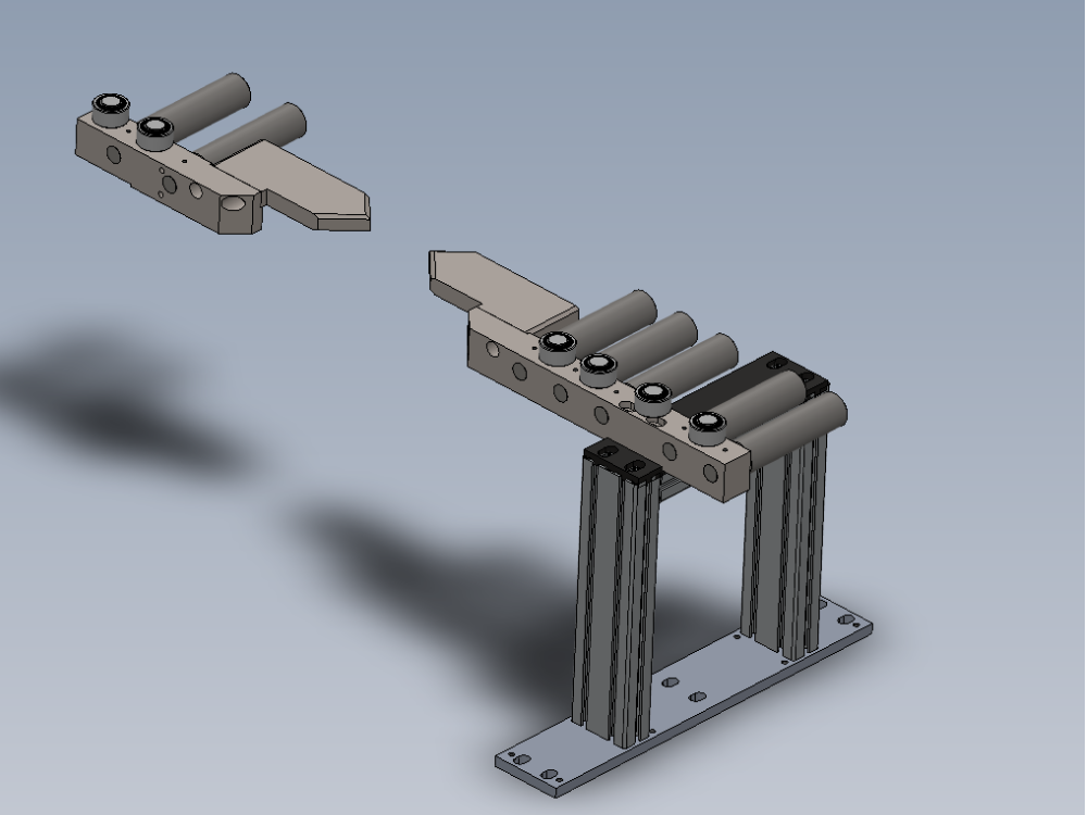
Parts Required
B0000062 Circlip 20mm External x 13
B0000415 Ball Bearing 20 I/D 32 O/D 7 Long + shields (INA) x 26
B0001176 washer : bearing shim x 16
D0010060 Roller Shaft Ø20 x 37.5 x 7
D0010061 Datum Roller Ø40 x 20 x 6
D0010396 Datum Roller Ø40 x 150mm x 7
D0010397 Shaft 20mm: 195mm Autoflow Roller x 7
D0015214 Roller Support Bar - Short x 1
D0015217 Profile Support Pad x 2
D0015218 Roller Support Bar - Long x 1
D0015220 Outfeed Roller Bed Support Frame x 1
D0015221 Outfeed Roller Bed Mounting Plate x 1
D0015348 MC Outfeed Roller Mounting Plate x 1
M0001006 Threaded insert M14/M8 30 long x 8
Étape 1 - Unless otherwise stated
Use locktite 243 on all fasteners
Use loctite 572 on all threaded pneumatic connection
Pen mark all fasteners to show finalised

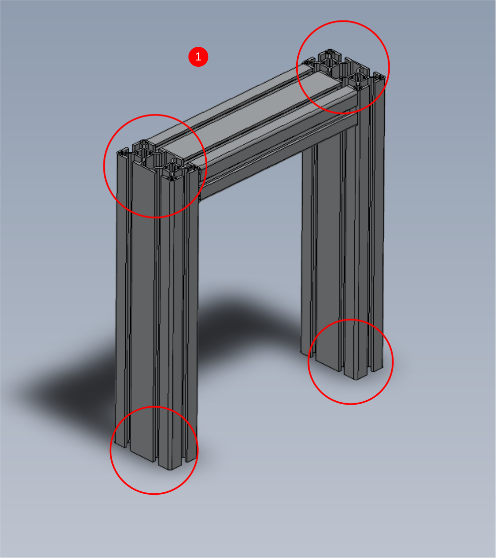
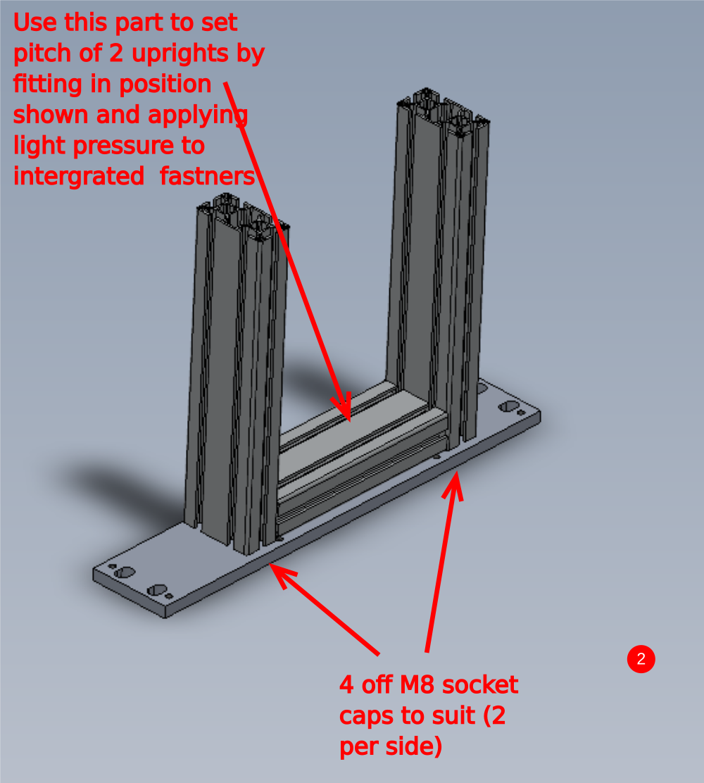
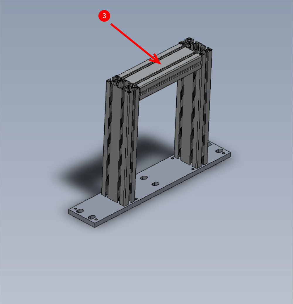
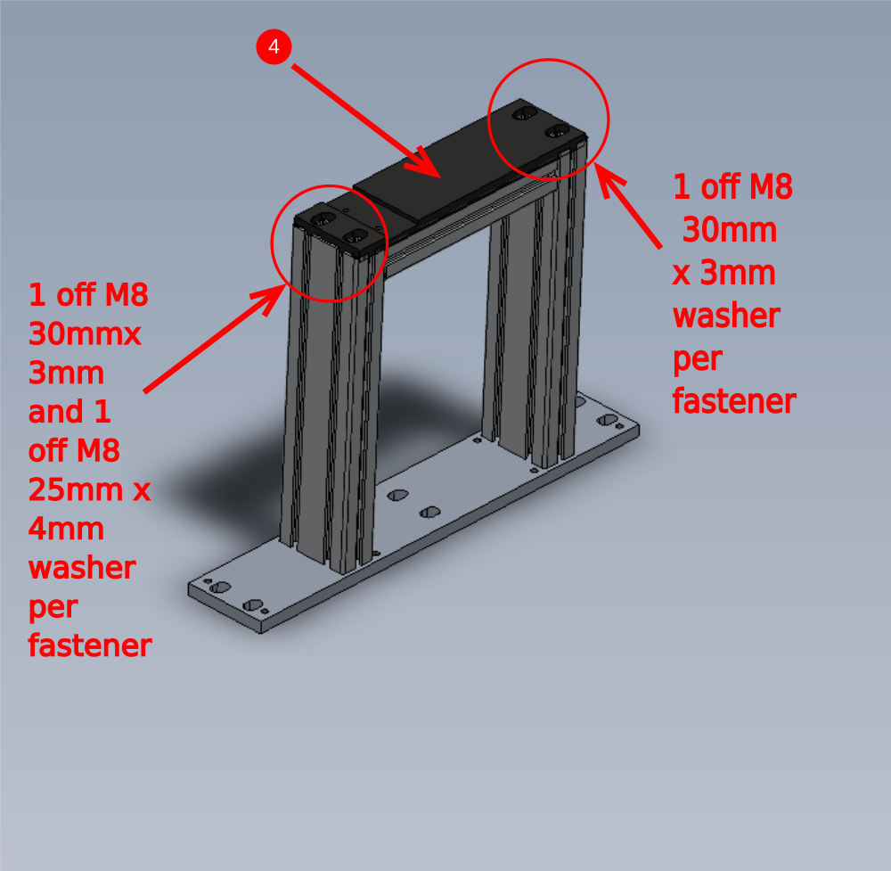
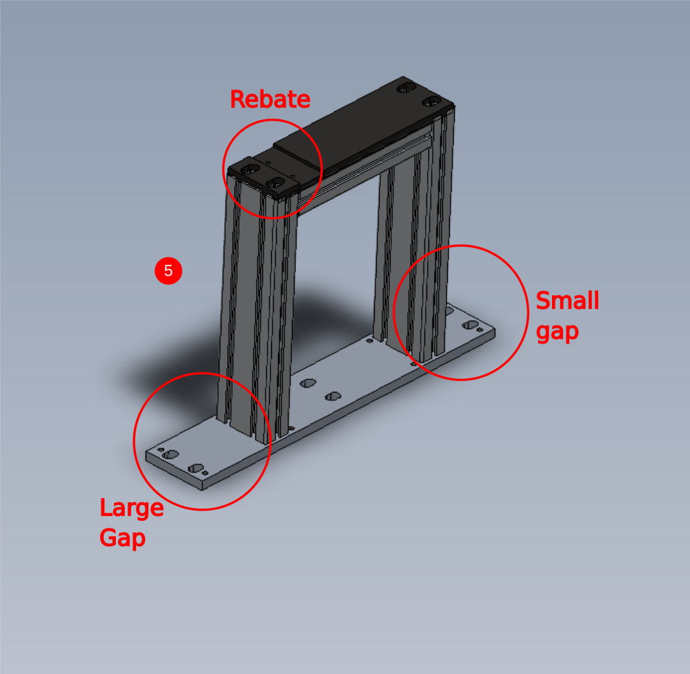
Étape 2 - Assemble maytec frame
1 Fit 8 off M0001006 Threaded insert M14/M8 30 long to indicated points . Secure with Loctite 290 once fitted
2 Attach to D0015221 Outfeed Roller Bed Mounting Plate using M8 socket caps long enough to fix into m8 insert in the profile
3 Move piece indicated to top position and apply light pressure to integrated fixings
4 Attach D0015348 MC Outfeed Roller Mounting Plate again calculating correct M8 socket cap length . See picture for details of washers. Do not use adhesive on these bolts
5
Étape 3 - Bearing fitment
Ensure bearing fit is checked when assembling parts . Minimal resistance should be required to fit these bearings into their respective rollers . Bearing should have enough contact on outer race that it will not rotate in the roller when turned
If fit is to tight inspect roller bore size
If fit is too loose, inspect to see within tolerance and if so , degrease and use bearing retaining compound

Étape 4 - Warning
excessive use of bearing fit can lead to bearing failure.
Ensure only 2 matchhead size drops are used per bearing and smeared around shaft before fitting bearing

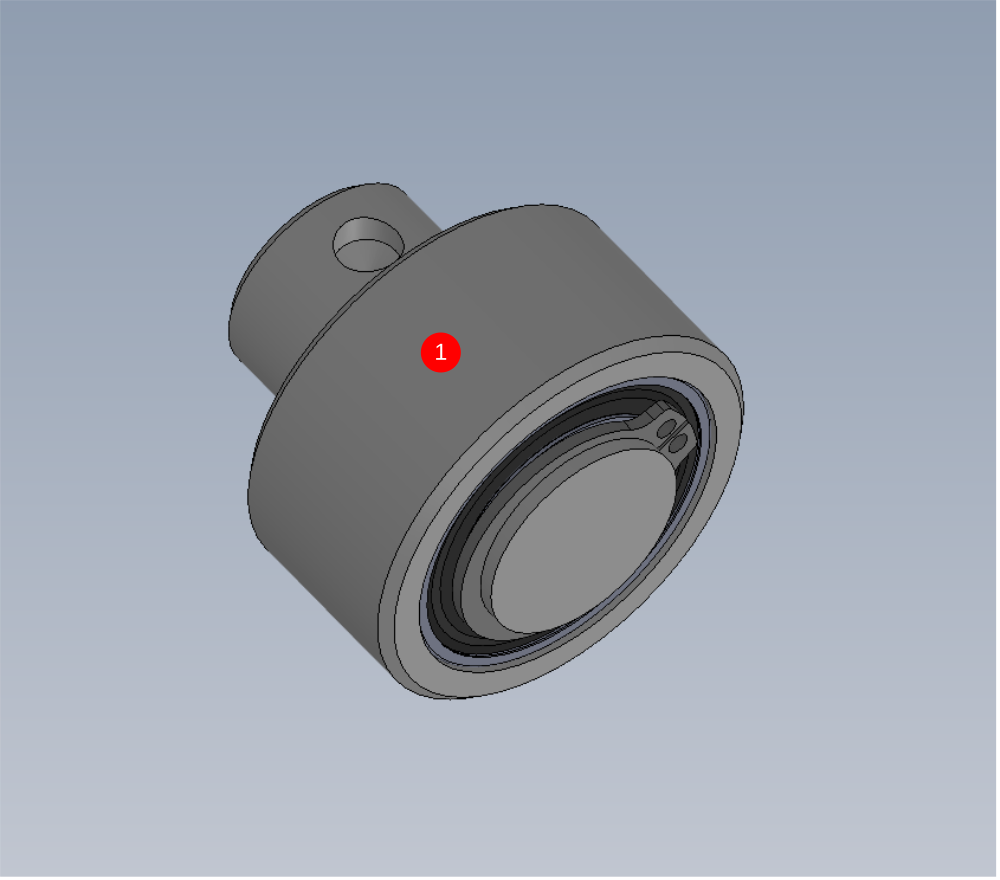
Étape 5 - Fit bearings to low rollers
6 off
Fit 2 off B0000415 bearing into D0010061 Datum Roller Ø40 x 20
Ensure bearings are pressed in far enough to be seated correctly on the shoulder below


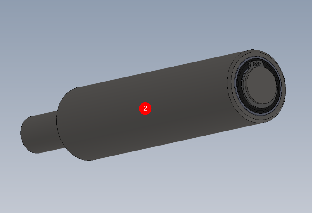
Étape 6 - Fit bearings to long rollers
7 off
Fit 2 off B0000415 bearing into D0010396 Datum Roller Ø40 x 150mm
Ensure bearings are pressed in far enough to be seated correctly on the shoulder below


Étape 7 - Check fit of shafts in bearings
Check fit of following parts .
Shafts should pass through bearings with only slight resistance . All inner bearing faces should have contact to shaft and rotate when the shaft is turned
Proceed to step 8 if fit is correct
If shafts are tight check drawing and inspect size of shaft .
If shaft slides through easily, then follow step 7
check these parts
D0010060 Roller Shaft Ø20 x 37.5 x 7
D0010061 Datum Roller Ø40 x 20 x 7
D0010396 Datum Roller Ø40 x 150mm x 7
D0010397 Shaft 20mm: 195mm Autoflow Roller x 7

Étape 8 - Degrease and bearing fit
Thoroughly degrease all parts with FE10 solvent
1 Fit 20mm external circlip to shaft
2 Fit roller to shaft
3 Add 3 drops of Loctite 641 bearing retainer to indicated area and smear around the shaft
4 Move shaft to shown position and add 3 more drops of bearing fit to indicated face and smear around
5 Position roller against circlip and remove any excess bearing fit with rag
6 Leave roller in a vertical position to allow bearing fit to cure


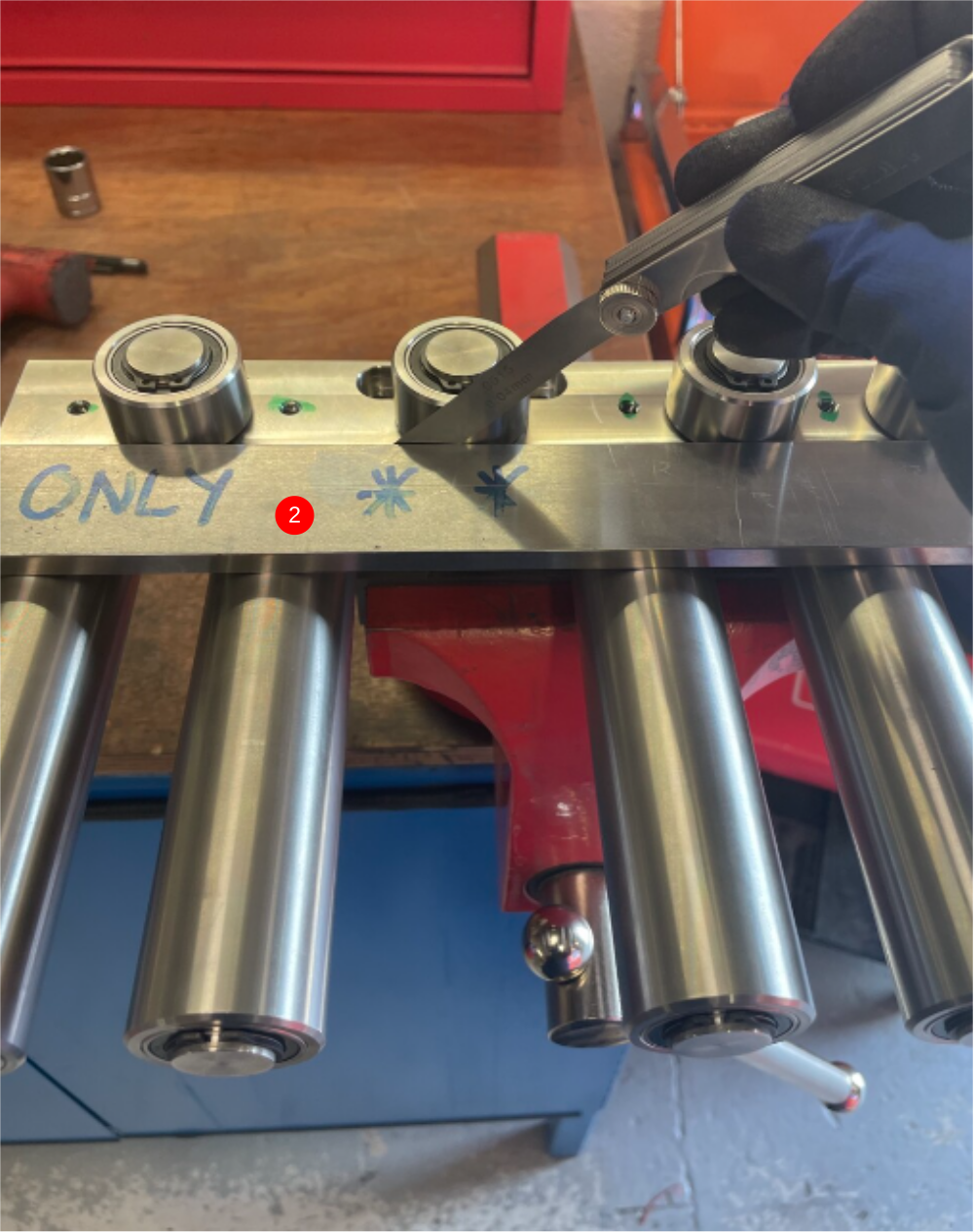
Étape 9 - Caution
It is vital that shaft dimples are correctly aligned for Fixing grubscrews to locate properly
To check correct alignment
Insert shaft and visually align dimple through grub screw hole
Insert grub screw and fasten
Wind grub screw out 1/2 turn
Shaft should be able to move slightly , but not be retracted from bore.
This will confirm grubscrew and dimple are correctly aligned

Étape 10 - Add circlip and fit roller
1 6 off
2 7 off
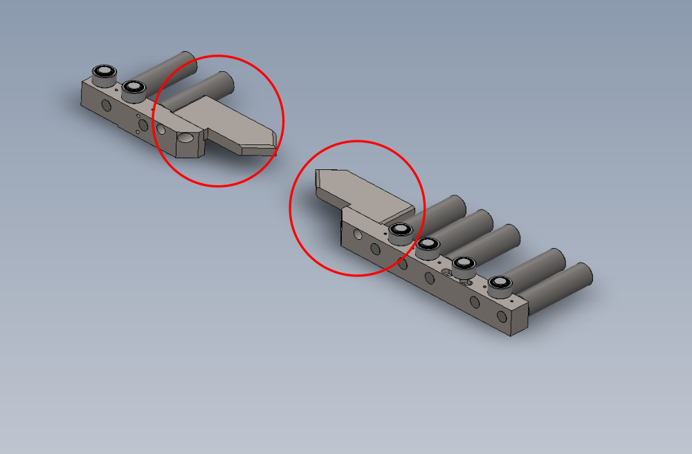
Étape 11 - Mount rollers
mount rollers to bases as shown .
Secure with M6 x 10 kcp grubscrews


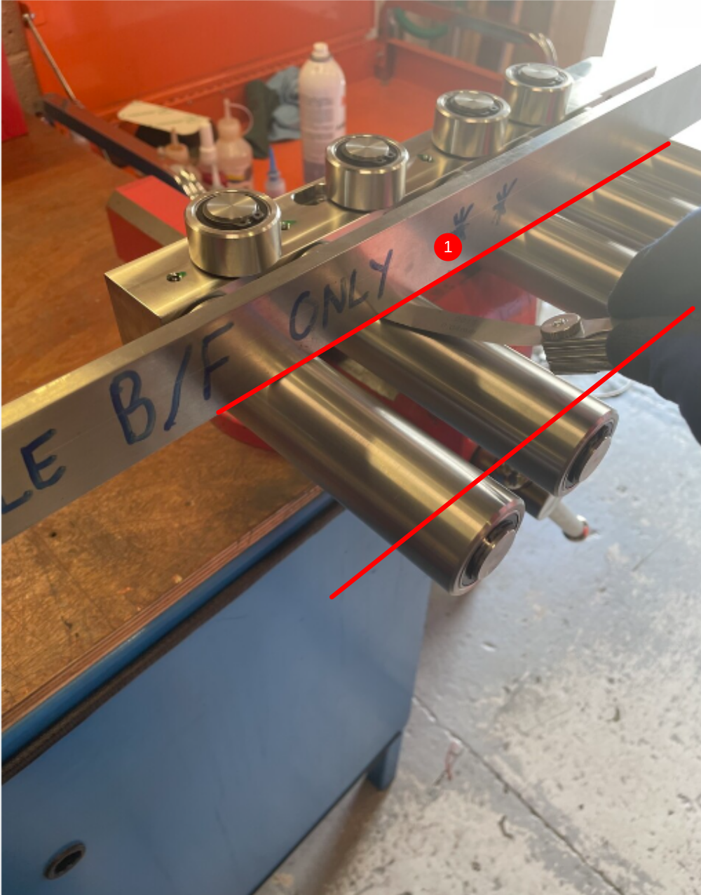
Étape 12 - Quality check rollers and position
Check alignment of rollers as shown
1 Check with straight edge at both indicated points for roller alignment
Report any gaps bigger than 0.002" 0.05mm
2 Check with straight edge at indicated point for roller alignment
Report any gaps bigger than 0.002" 0.05mm
Étape 13 - Mount Cut tables
Mount D0015217 Profile Support Pad x 2 as shown
Use 4 off M10 x 25 socket caps to secure
Use straight edge to set pads in line with rollers to 0.002" 0.05 mm or less . Report any discrepancies
Draft
 Français
 English
 Deutsch
 Español
 Italiano
 Português