Instructions for bench assembly of v notch components

Difficulté
Moyen
Durée
6 heure(s)
Sommaire
- 1 Introduction
- 2 Étape 1 - Unless otherwise stated
- 3 Étape 2 - Saw motor bar assemblies
- 4 Étape 3 - Prepare Adjustment bolts
- 5 Étape 4 - Check M16 thread and add M8 set bolt
- 6 Étape 5 - M0001093 Shaft Clamping Element (Ø15-20 shafts)
- 7 Étape 6 - Assemble motor mounts
- 8 Étape 7 - Fit to Saw motor bar
- 9 Commentaires
Introduction
Tools Required
Standard hex key set
Standard spanner set
Standard HSS drill set
Vernier 150mm
1 meter straight edge
1" parallel blocks
40mm shaft pin jigs
Feeler gauge set
Internal circlip pliers
External circlip pliers
8mm hand reamer
Parts Required
B0000109 Linear Bearing (IKO) 40 D x 62 D x 80 L x 8
B0000427 Leadscrew Ø25x10 435 Long x 1
B0001047 Fixed Bearing Support Block Ø17 x 1
B0001120 Circlip 62mm External x 16
B0001127 ROTEX GS Coupling Ø14/Ø15 Bore & Key (98 Shore Spider) x 1
B0001134 Ball Bearing 15ID 35OD 11 Long x 10
C0001122K Servo Motor: Beckhoff AM8032-1E10 (Keyed) x 1
D0010132 SZ Drive Mount Plate x 1
D0010563 Y Axis Servo Mount x 1
D0015147 V Notch Upper Support Bar x 1
D0015148 V Notch Lower Support Bar x 1
D0015149 VZ Shaft End Plate x 4
D0015150 Shaft 40mm: 1350 ZX V Notch Saw Motor Slide x 4
D0015152 V-Notch Upper Moving Bar x 1
D0015153 V-Notch Rear Moving Bar x 1
D0015154 V-Notch Front Moving Barx1
D0015157 Saw Motor Bar x 4
D0015158 Shaft 40mm: 190mm ZX V Notch Saw Motor Slide x 8
D0015159B Saw Motor Adjustment Screwx 4
D0015160 Saw Motor Block x 4
D0015164 VY Leadscrew Block x 1
D0015166 VY Motor Mounting Plate x1
D0015258 Upper Link Mount 1 x 1
D0015259 Upper Link Mount 2 x 1
D0015260 Upper Link x 2
D0015261 Lower Link x 2
D0015262 Lower Link Mount x 2
D0015263 Mid Link Shaft x 2
D0015264 Lower Link Shaft x 2
M0001093 Shaft Clamping Element (Ø15-20 shafts) x 16
Étape 1 - Unless otherwise stated
Use Loctite 243 on all fasteners
Use Loctite 572 on all threaded pneumatic connection
Pen mark all fasteners to show finalised

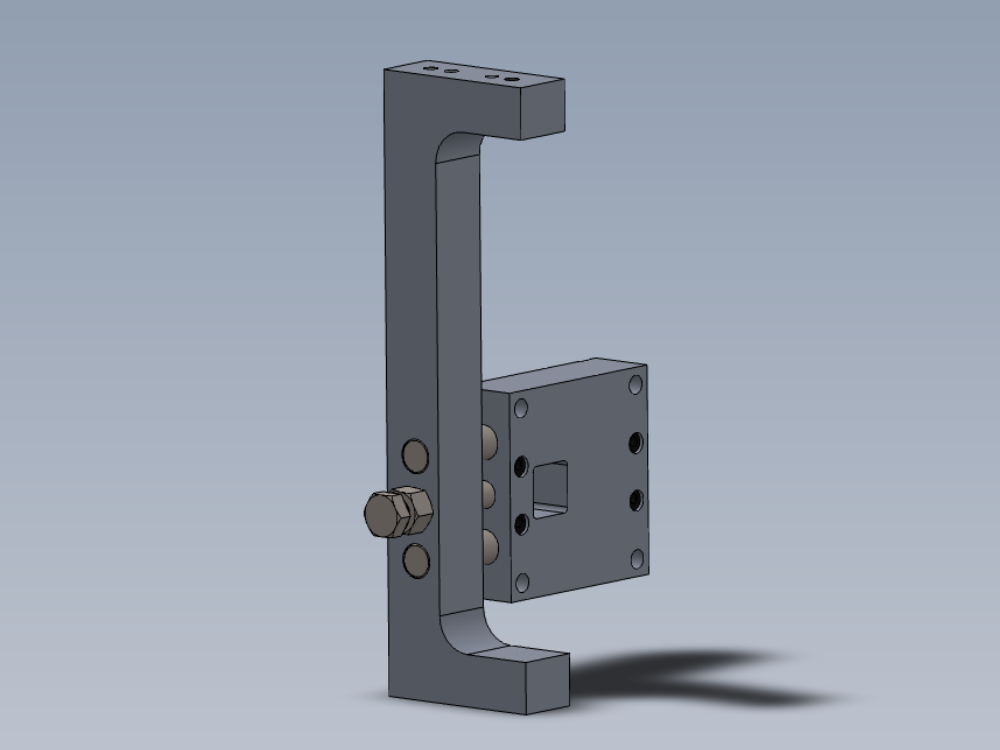
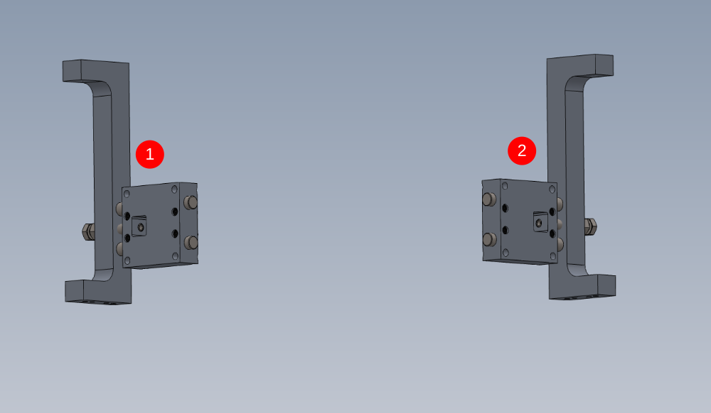
Étape 2 - Saw motor bar assemblies
2 off No. 1 and 2 off No.2 required assembling
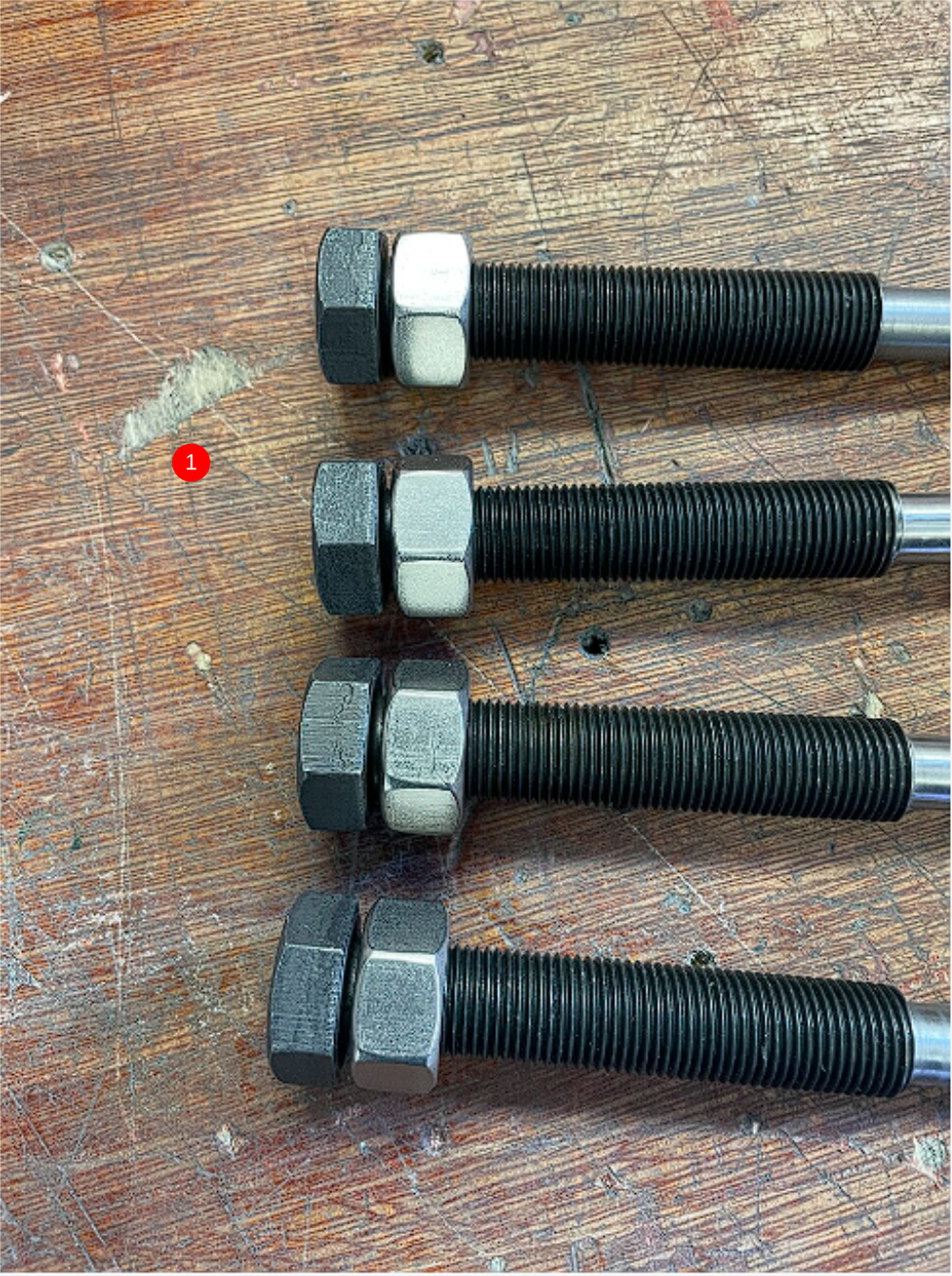
Étape 3 - Prepare Adjustment bolts
4 off D0015159B Saw Motor Adjustment Screw require M8 x 70 set bolts cutting to suit M8 thread depth on adjuster bolts
Adjust each bolt individually as discrepancies in thread depth are possible

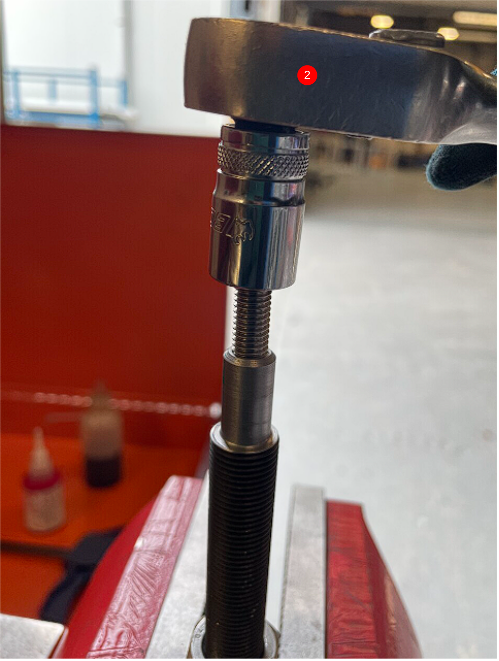
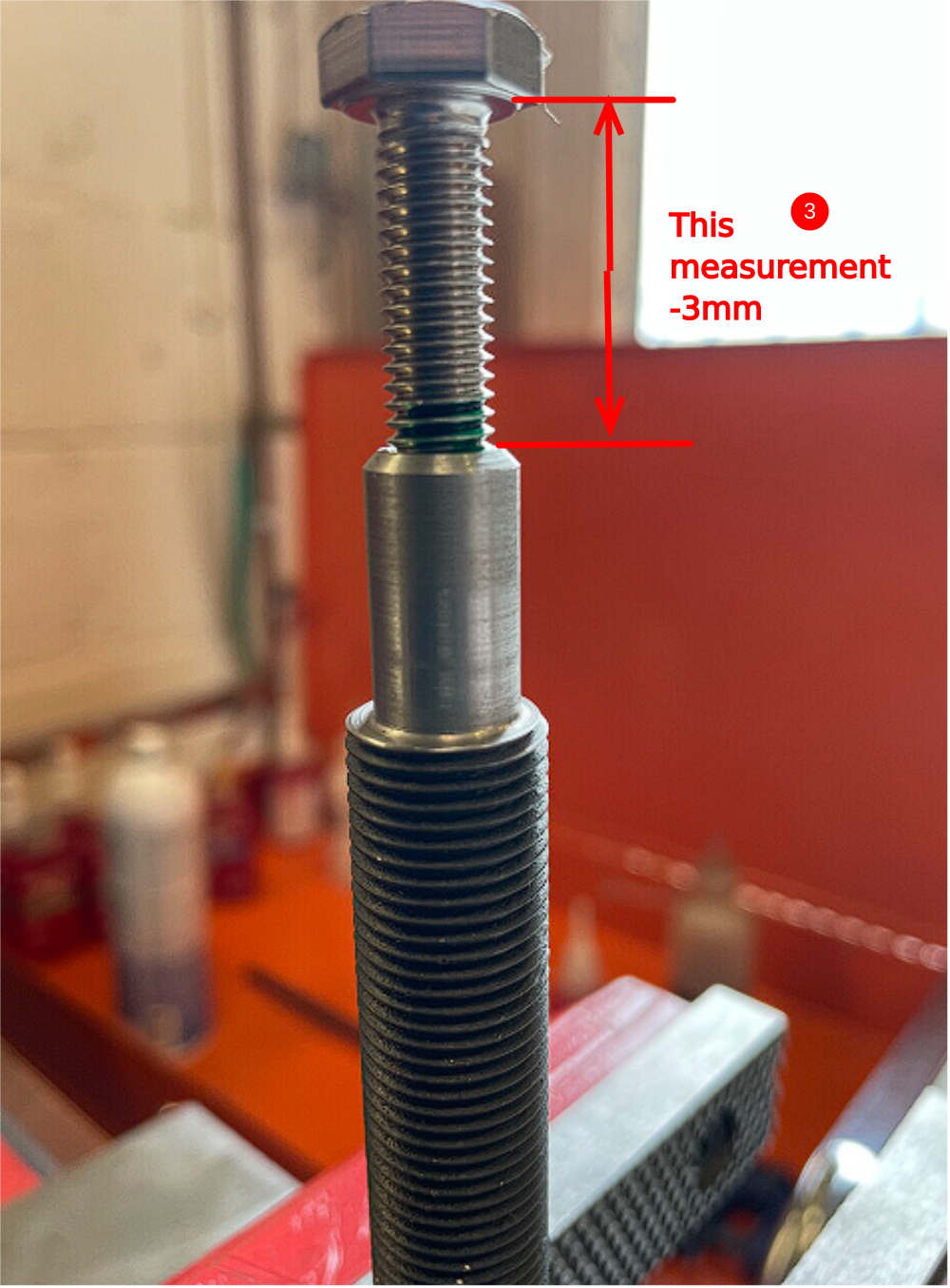
Étape 4 - Check M16 thread and add M8 set bolt
1 Fit M16 x 1.5 nut to each screw . Ensure nut winds fully to face of bolt
2 Fit M8 x 70 set bolt to each bolt. Treat the M8 and M16 adjuster bolt as pairs from this point and do not mix up. Wind the M8 set fully into the adjuster bolt and tighten
3 Measure the gap indicated , and minus 3mm. This will give you the exact amount that needs removing from the M8 bolt
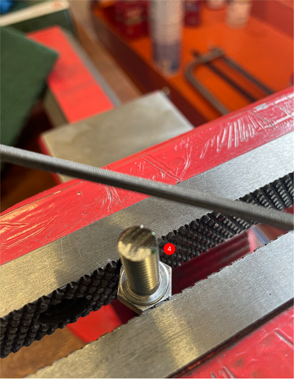
4 Remove M8 from adjuster bolt, and cut exact amount calculated off the end of the M8 bolt . Dress end
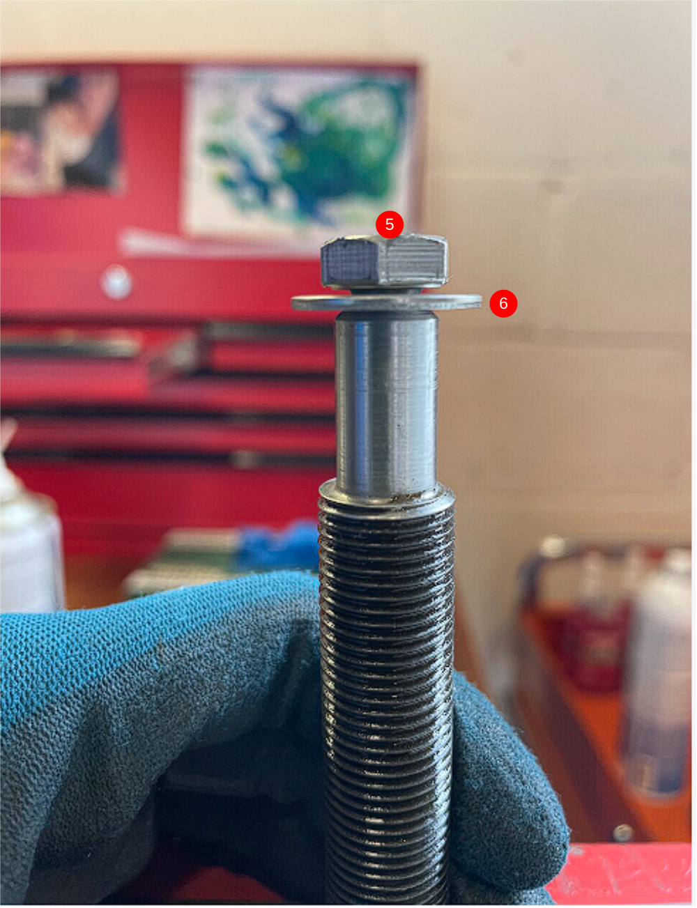
5 Add M8 penny washer to cut M8 bolt , refit to adjuster bolt. Tighten fully.
6 M8 Set bolt should fully tighten and leave a gap big enough for penny washer to float around
Repeat for remaining 3 adjuster bolts
Étape 5 - M0001093 Shaft Clamping Element (Ø15-20 shafts)
M0001093 Shaft Clamping Element require the issued M6 x 35 cap head to be swapped for a M6 x 30 socket cap.
Swap bolts in all 16, paying attention to correct re assembly


Étape 6 - Assemble motor mounts
4 off
Fit 2 off D0015158 Shaft 40mm: 190mm ZX V Notch Saw Motor Slide into D0015160 Saw Motor Block with 4 off M0001093 Shaft Clamping Element
Ensure flats of M0001093 Shaft Clamping Element are aligned correctly to allow shaft to pass through
Only apply light tension to these bolts as adjustment will be required later on
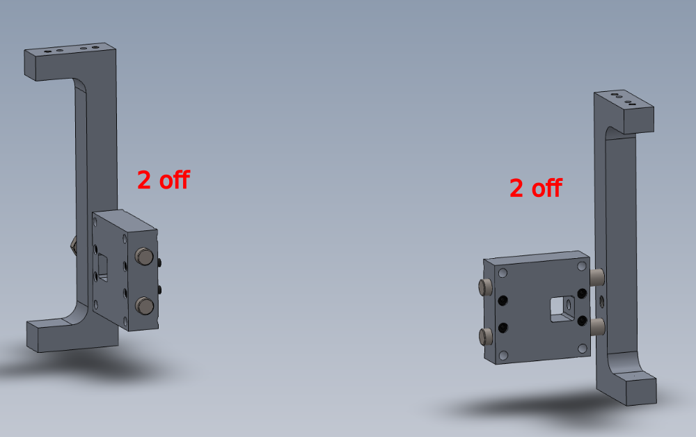
Étape 7 - Fit to Saw motor bar
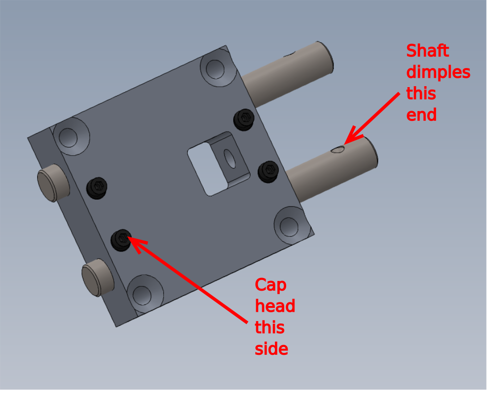
Fit assemblies as shown
Secure shafts with M8 x 12 KCP grubscrews
Make 2 off each hand
Draft
 Français
 English
 Deutsch
 Español
 Italiano
 Português