| [version en cours de rédaction] | [version en cours de rédaction] |
| Ligne 61 : | Ligne 61 : | ||
D0015149 VZ Shaft End Plate x 4 | D0015149 VZ Shaft End Plate x 4 | ||
| − | |||
| − | |||
D0015152 V-Notch Upper Moving Bar x 1 | D0015152 V-Notch Upper Moving Bar x 1 | ||
Version du 8 mars 2024 à 13:38
Instructions for bench assembly of v notch components

Difficulté
Moyen
Durée
8 heure(s)
Sommaire
- 1 Introduction
- 2 Étape 1 - Unless otherwise stated
- 3 Étape 2 - Saw motor bar assemblies
- 4 Étape 3 - Prepare Adjustment bolts
- 5 Étape 4 - Check M16 thread and add M8 set bolt
- 6 Étape 5 - M0001093 Shaft Clamping Element (Ø15-20 shafts)
- 7 Étape 6 - Assemble motor mounts
- 8 Étape 7 - Fit to Saw motor bar
- 9 Étape 8 - Set distance
- 10 Étape 9 - Warning!
- 11 Étape 10 - Assemble leadscrew assembly
- 12 Étape 11 - Assemble motor assembly
- 13 Étape 12 - Greasing Point location
- 14 Étape 13 - combine servo assembly
- 15 Étape 14 - Assemble link bars
- 16 Étape 15 - Fit bearings
- 17 Étape 16 - Fit connector shafts
- 18 Étape 17 - Assemble link mounts
- 19 Étape 18 - Assemble bearing blocks
- 20 Étape 19 - Assemble Main Cross members
- 21 Étape 20 - Mount blocks and add setting jigs
- 22 Étape 21 - Set pitching of blocks
- 23 Étape 22 - Align with straight edge
- 24 Étape 23 - Dowel
- 25 Étape 24 - Finalise fixings
- 26 Étape 25 - Repeat steps 19 to 22
- 27 Commentaires
Introduction
Tools Required
Standard hex key set
Standard spanner set
Standard HSS drill set
Vernier 150mm
2 meter straight edge
40mm shaft pin jigs
Feeler gauge set
Internal circlip pliers
External circlip pliers
8mm hand reamer
Parts Required
B0000041 5 x 5 x 19 key x 1
B0000109 Linear Bearing (IKO) 40 D x 62 D x 80 L x 8
B0000427 Leadscrew Ø25x10 435 Long x 1
B0001047 Fixed Bearing Support Block Ø17 x 1
B0001120 Circlip 62mm External x 16
B0001127 ROTEX GS Coupling Ø14/Ø15 Bore & Key (98 Shore Spider) x 1
B0001134 Ball Bearing 15ID 35OD 11 Long x 10
C0001122K Servo Motor: Beckhoff AM8032-1E10 (Keyed) x 1
D0010132 SZ Drive Mount Plate x 1
D0010563 Y Axis Servo Mount x 1
D0015147 V Notch Upper Support Bar x 1
D0015148 V Notch Lower Support Bar x 1
D0015149 VZ Shaft End Plate x 4
D0015152 V-Notch Upper Moving Bar x 1
D0015153 V-Notch Rear Moving Bar x 1
D0015154 V-Notch Front Moving Barx1
D0015157 Saw Motor Bar x 4
D0015158 Shaft 40mm: 190mm ZX V Notch Saw Motor Slide x 8
D0015159B Saw Motor Adjustment Screwx 4
D0015160 Saw Motor Block x 4
D0015164 VY Leadscrew Block x 1
D0015166 VY Motor Mounting Plate x1
D0015258 Upper Link Mount 1 x 1
D0015259 Upper Link Mount 2 x 1
D0015260 Upper Link x 2
D0015261 Lower Link x 2
D0015262 Lower Link Mount x 2
D0015263 Mid Link Shaft x 2
D0015264 Lower Link Shaft x 2
M0001093 Shaft Clamping Element (Ø15-20 shafts) x 16
Étape 1 - Unless otherwise stated
Use Loctite 243 on all fasteners
Use Loctite 572 on all threaded pneumatic connection
Pen mark all fasteners to show finalised

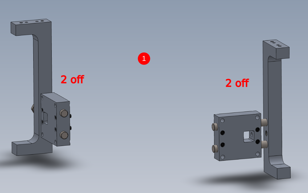
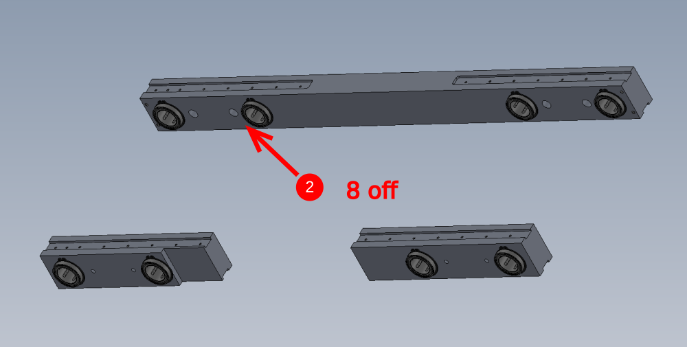
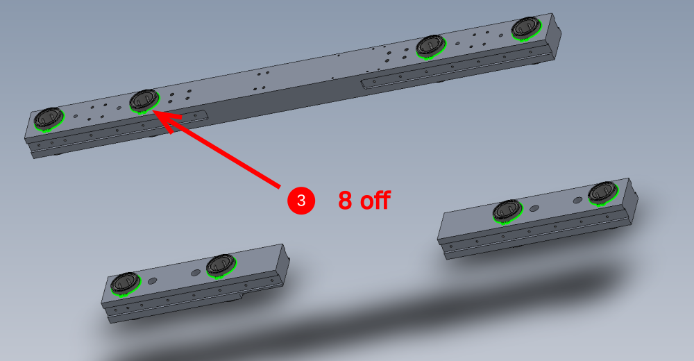
Étape 2 - Saw motor bar assemblies
2 off No. 1 and 2 off No.2 required assembling
Étape 3 - Prepare Adjustment bolts
4 off D0015159B Saw Motor Adjustment Screw require M8 x 70 set bolts cutting to suit M8 thread depth on adjuster bolts
Adjust each bolt individually as discrepancies in thread depth are possible

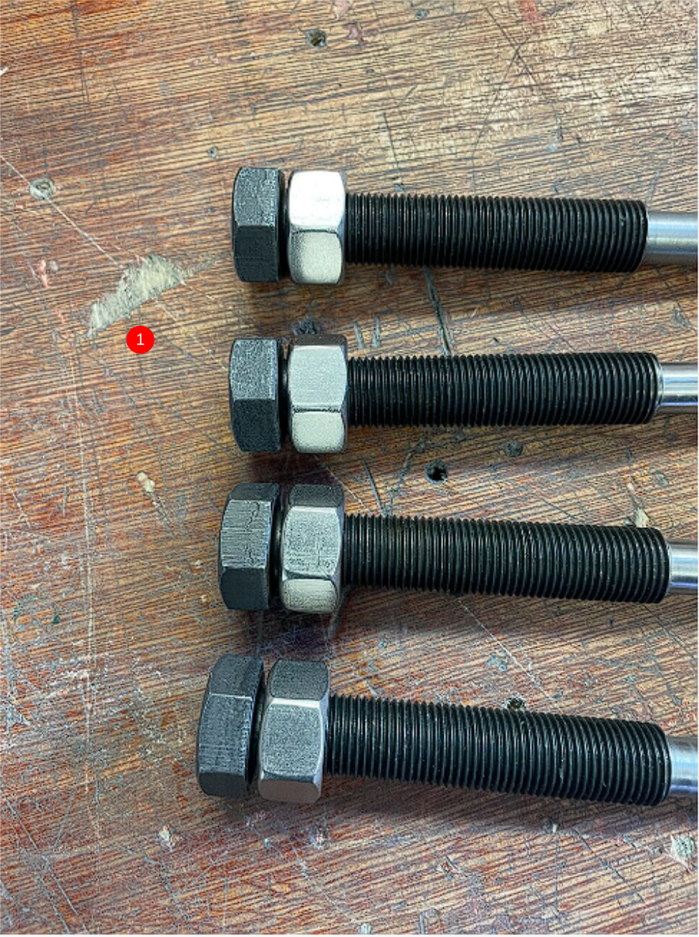
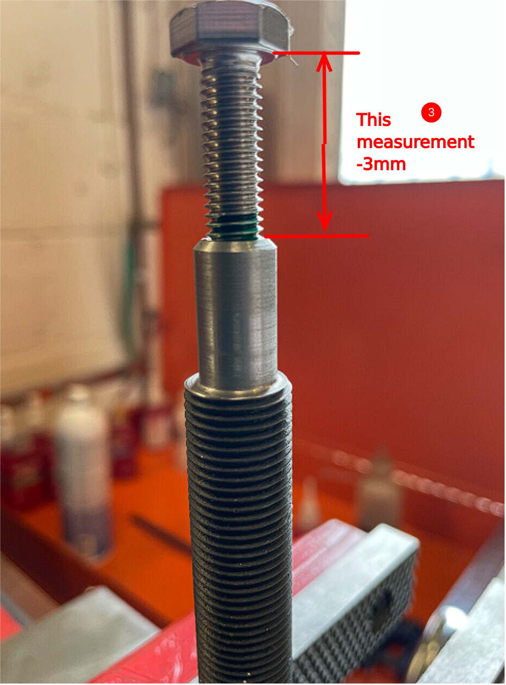
Étape 4 - Check M16 thread and add M8 set bolt
1 Fit M16 x 1.5 nut to each screw . Ensure nut winds fully to face of bolt
2 Fit M8 x 70 set bolt to each bolt. Treat the M8 and M16 adjuster bolt as pairs from this point and do not mix up. Wind the M8 set fully into the adjuster bolt and tighten
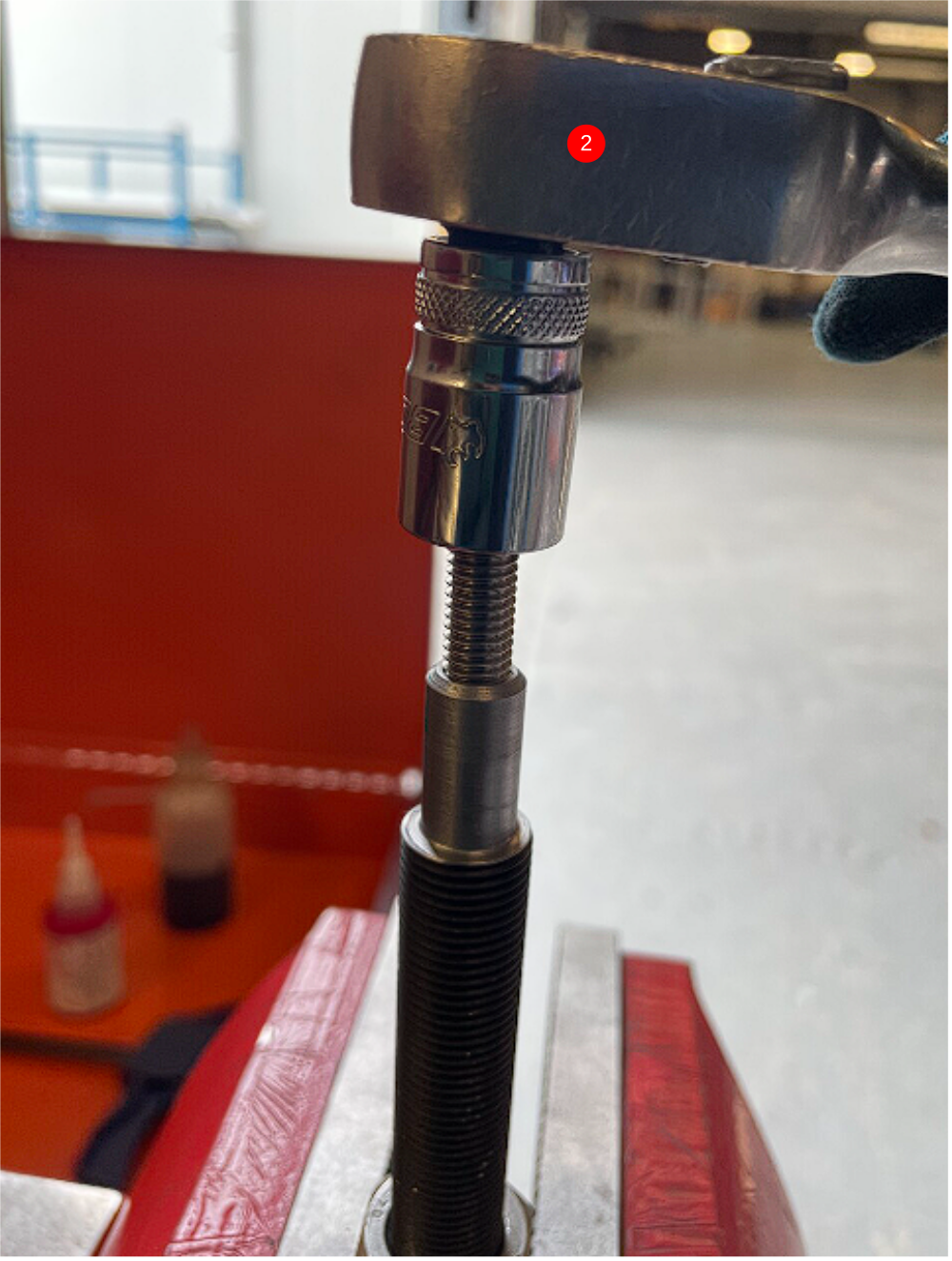
3 Measure the gap indicated , and minus 3mm. This will give you the exact amount that needs removing from the M8 bolt
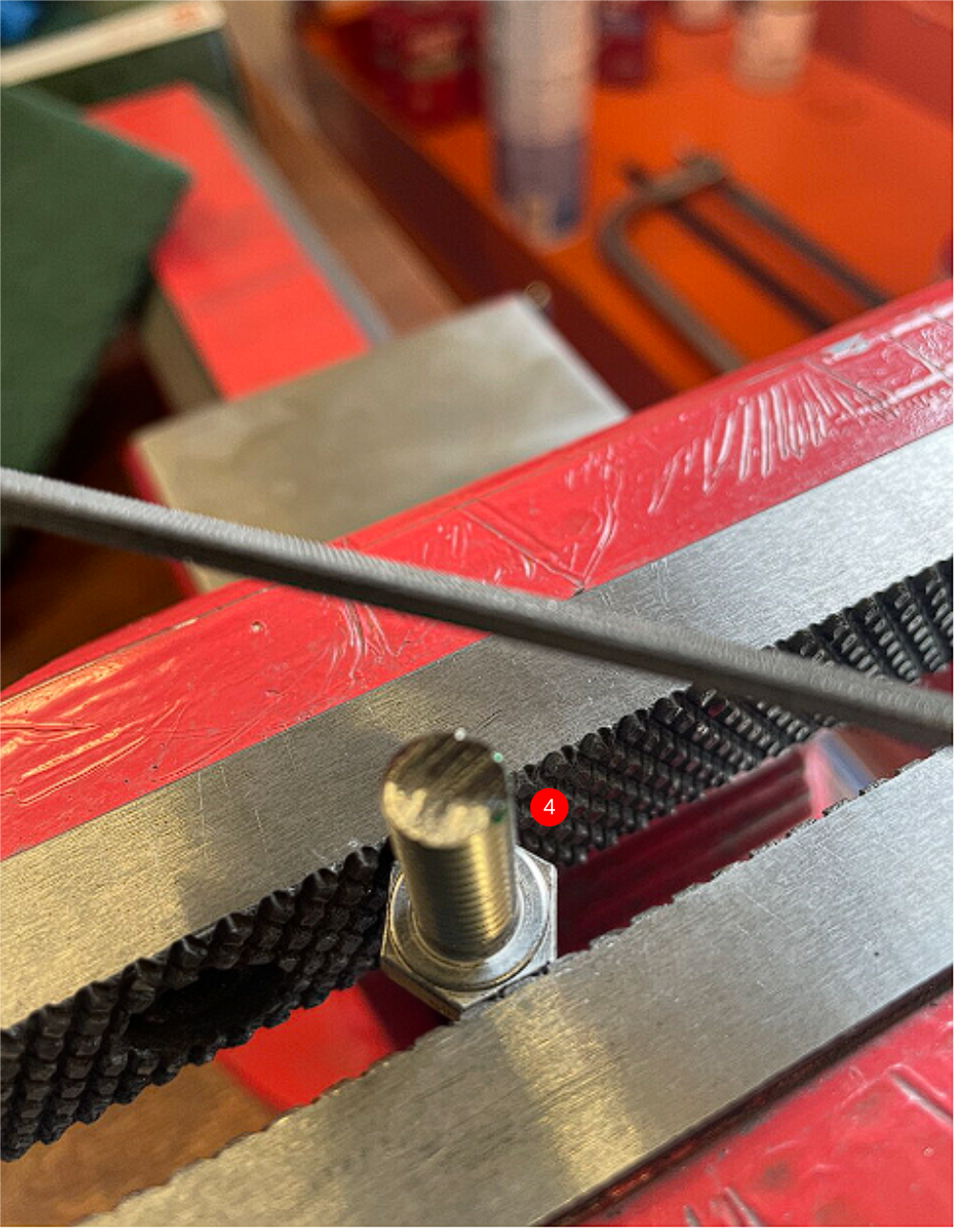
4 Remove M8 from adjuster bolt, and cut exact amount calculated off the end of the M8 bolt . Dress end
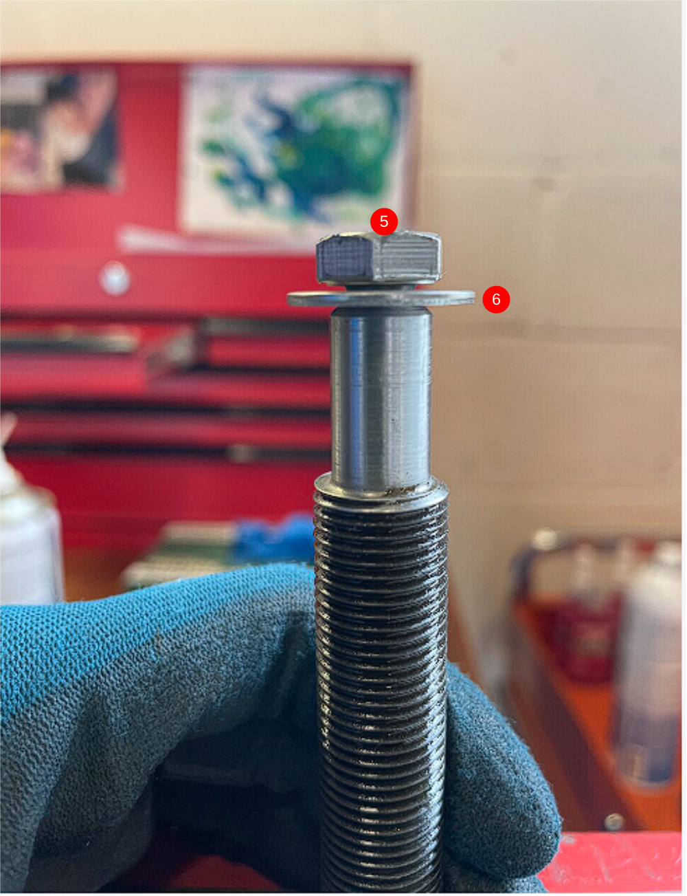
5 Add M8 penny washer to cut M8 bolt , refit to adjuster bolt. Tighten fully.
6 M8 Set bolt should fully tighten and leave a gap big enough for penny washer to float around
Repeat for remaining 3 adjuster bolts
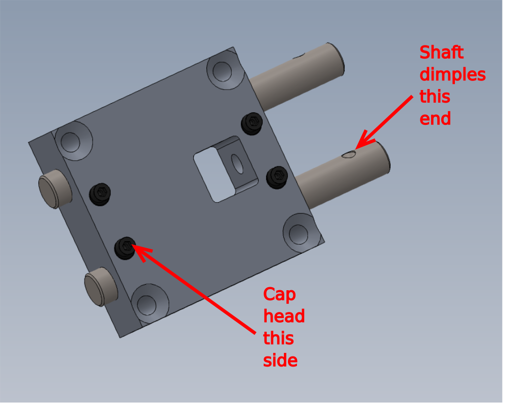
Étape 5 - M0001093 Shaft Clamping Element (Ø15-20 shafts)
M0001093 Shaft Clamping Element require the issued M6 x 35 cap head to be swapped for a M6 x 30 socket cap.
Swap bolts in all 16, paying attention to correct re assembly


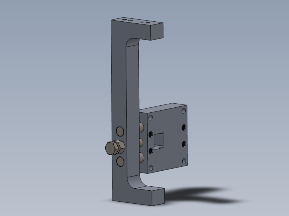
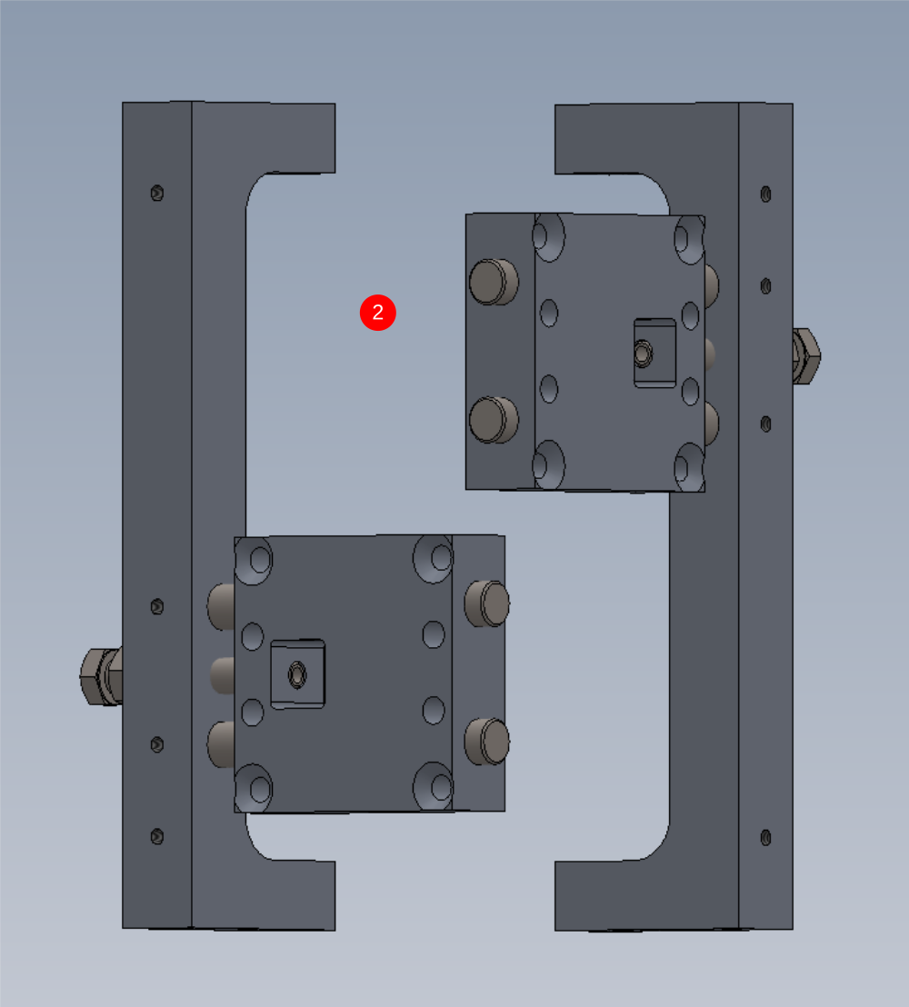
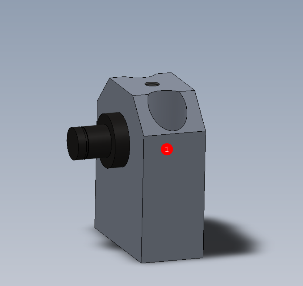
Étape 6 - Assemble motor mounts
4 off
Fit 2 off D0015158 Shaft 40mm: 190mm ZX V Notch Saw Motor Slide into D0015160 Saw Motor Block with 4 off M0001093 Shaft Clamping Element
Ensure flats of M0001093 Shaft Clamping Element are aligned correctly to allow shaft to pass through
Only apply light tension to these bolts as adjustment will be required later on

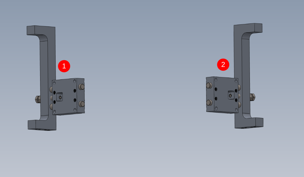
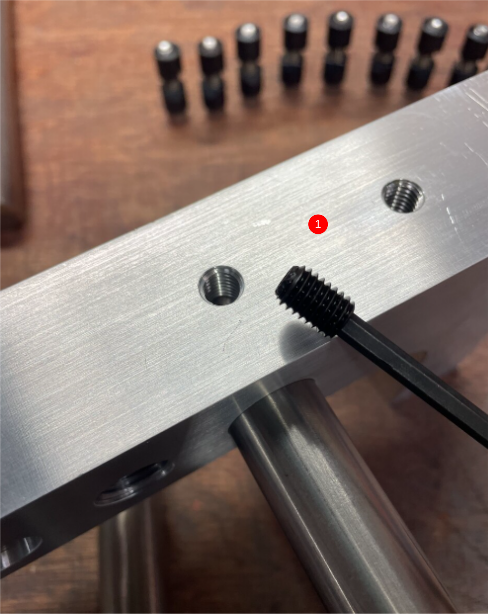
Étape 7 - Fit to Saw motor bar
1 Fit assemblies as shown
Secure shafts with M8 x 12 KCP grubscrews
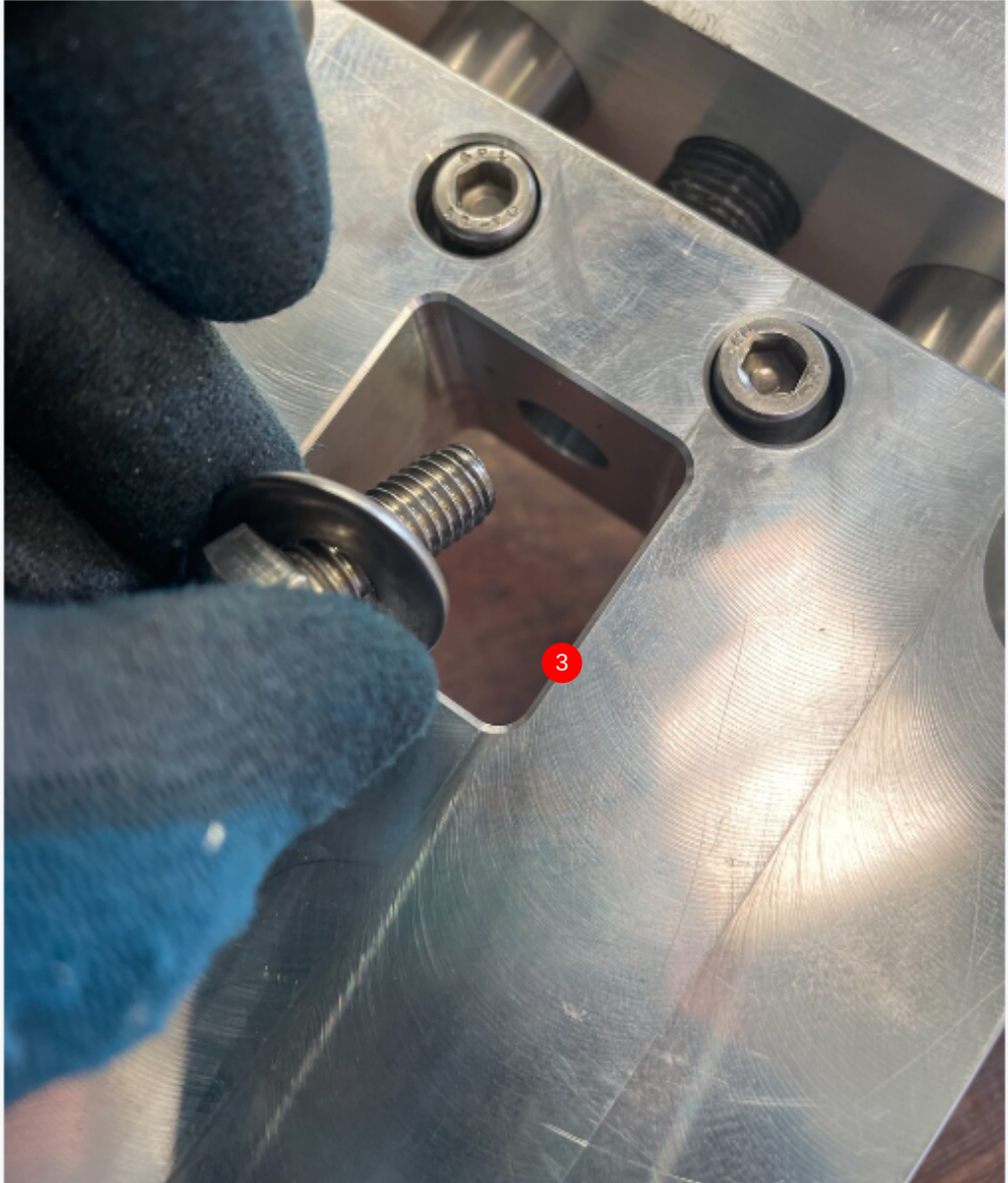
2 Add previously assembled M16 adjusted bolts . Remove m8 and washer , apply copper slip to thread and machined shank of bolt and wind into assembly .
3 Apply loctite 270 to m8 bolt and refit and thoroughly tighten Make 2 off each hand


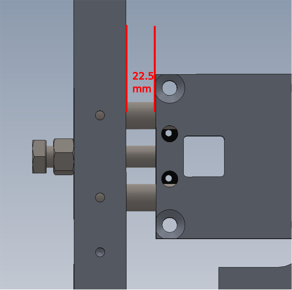
Étape 8 - Set distance
Set gap to 22.5mm and lock off m16 nut and ensure measurement isn't effected from tightening
Tolerance -+0.1mm


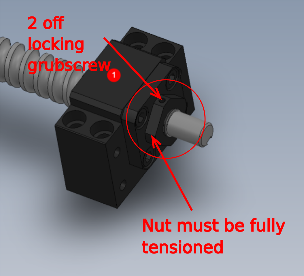
Étape 9 - Warning!
in the following steps
Attach B0001047 Fixed Bearing Support Block Ø17 x 1 as shown to B0000427 Leadscrew Ø25x10 435 Long . Ensure locking grubscrews are tensioned in lock nut once tightened
It is vital that the indicated part is correctly tightened and securing grub screws are locked off when tensioned.
Qualities have arisen from this area so please ensure correct practice is followed when assembling
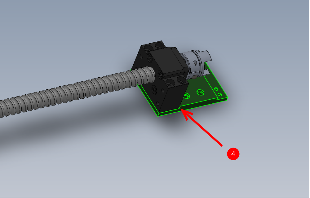
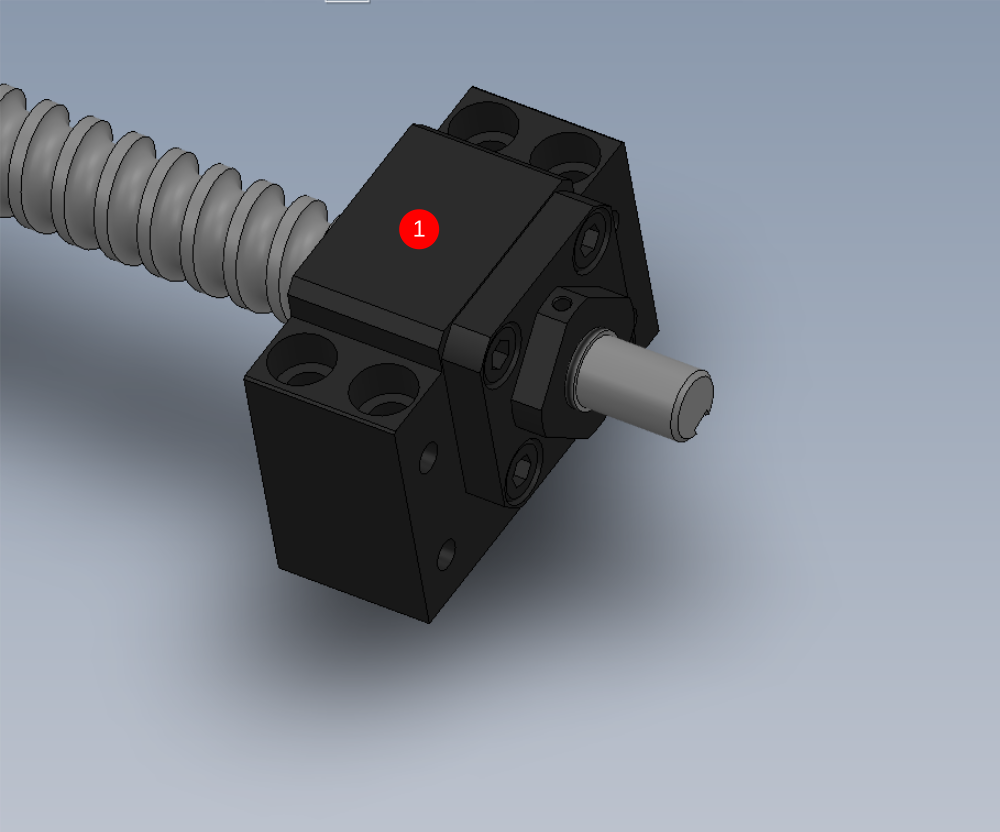
Étape 10 - Assemble leadscrew assembly
1 Attach B0001047 Fixed Bearing Support Block Ø17 x 1 as shown to B0000427 Leadscrew Ø25x10 435 Long . Ensure locking grubscrews are tensioned in lock nut once tightened
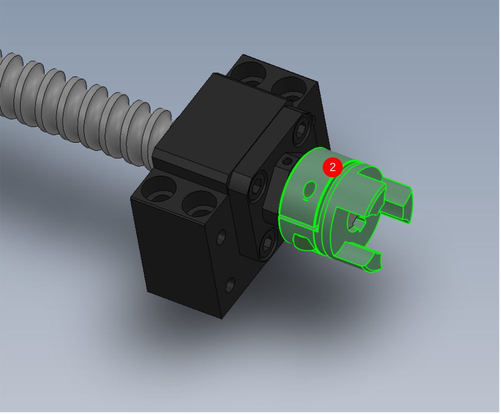
2 Insert B0000041 key into leadscrew and fit B0001127 ROTEX GS Coupling Ø14/Ø15 Bore & Key (98 Shore Spider) , push to should and finalise coupling m6 fastener
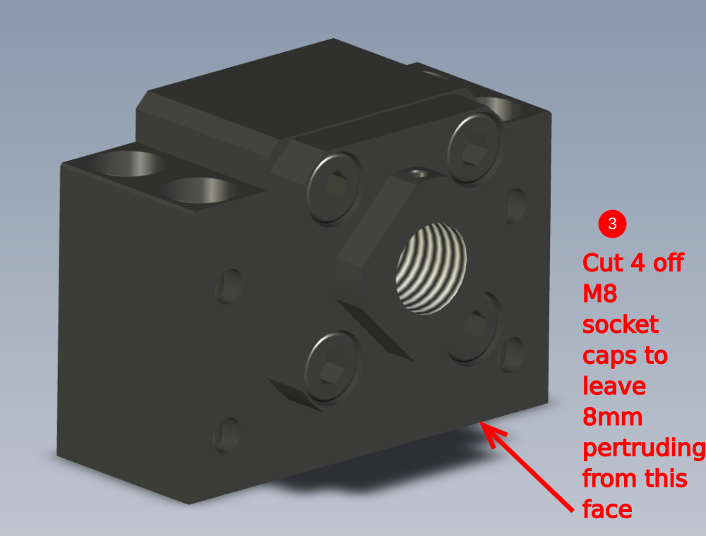
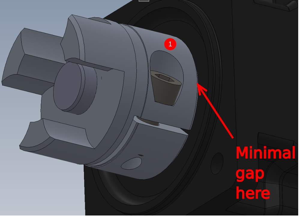
3 Cut 4 off M8 socket caps to leave 8mm protrusion from indicated face
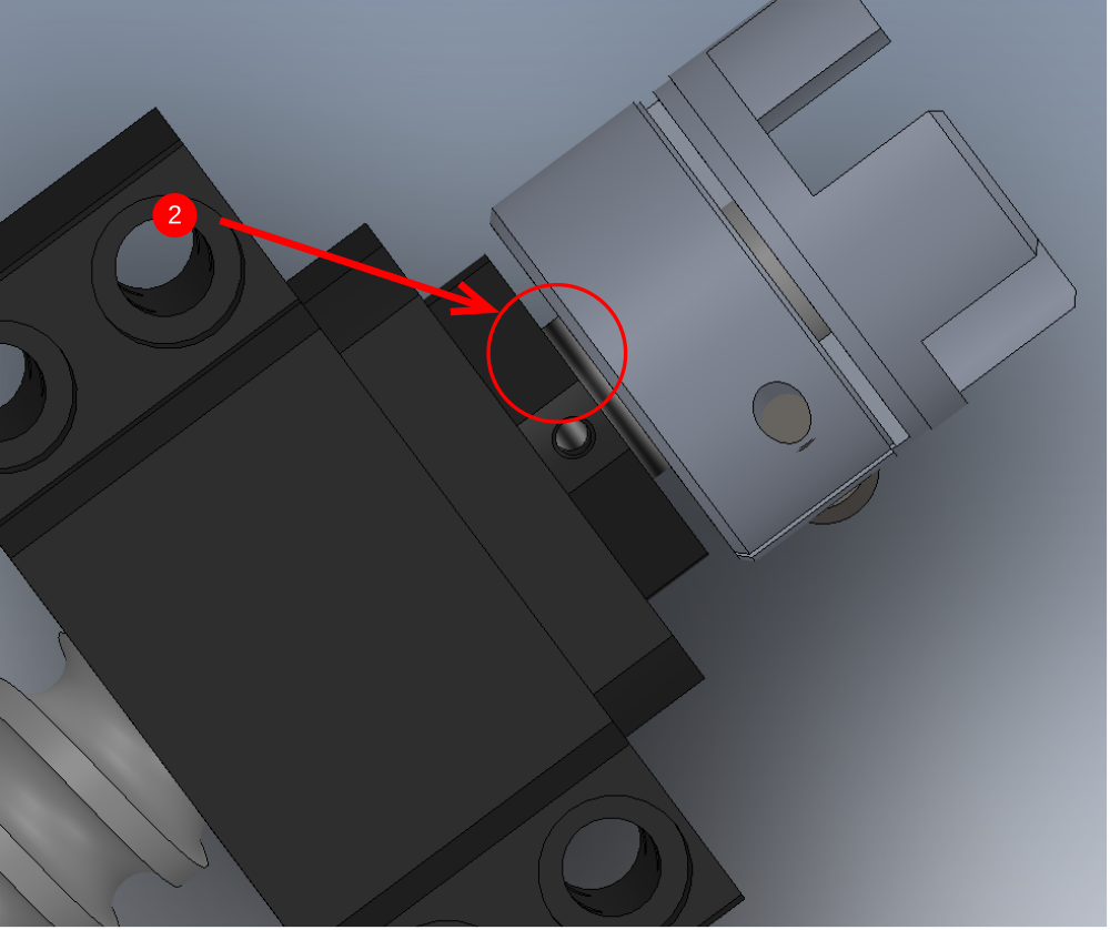
4 Attach to D0010132 SZ Drive Mount Plate ensuring indicated faces are touching

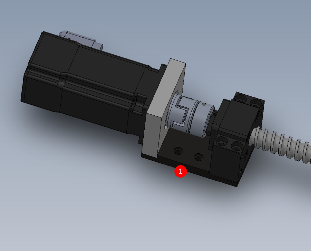
Étape 11 - Assemble motor assembly
1 Attach B0001127 ROTEX GS Coupling Ø14/Ø15 Bore & Key (98 Shore Spider) to C0001122K Servo Motor: Beckhoff AM8032-1E10 (Keyed). Set coupling close to motor face (1mm)
2 Fit D0010563 Y Axis Servo Mount x 1 using 4 off M5 x 16 socket caps
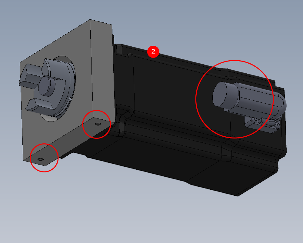
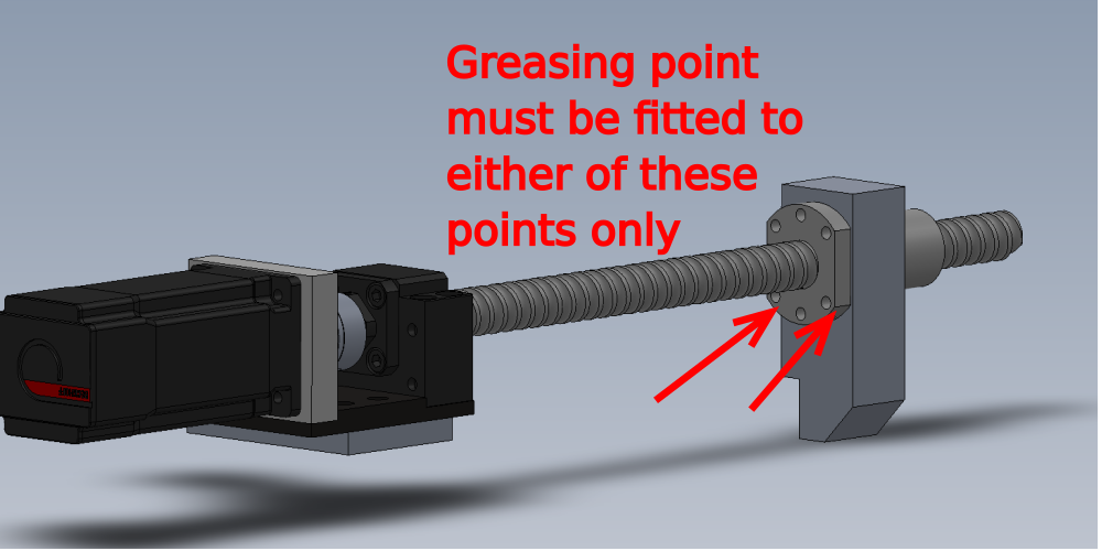
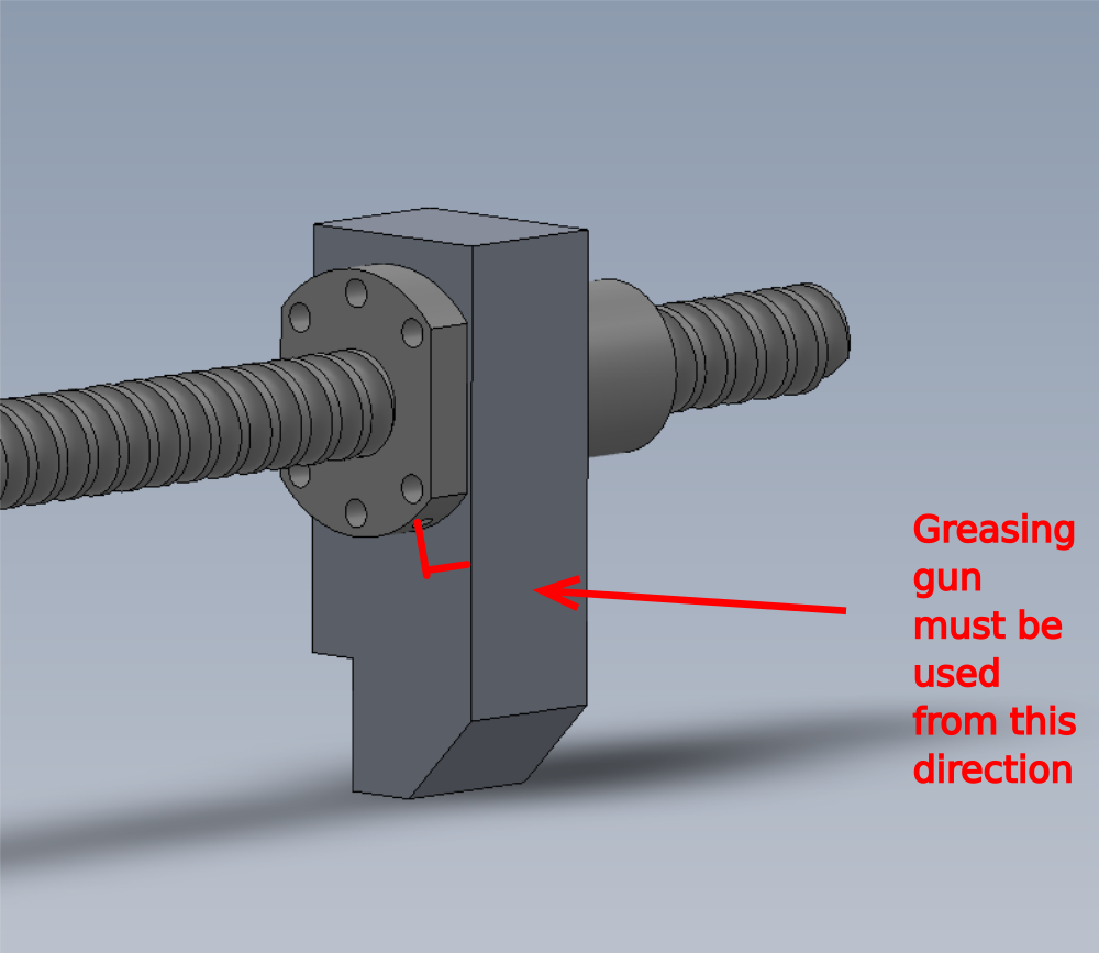
Étape 12 - Greasing Point location
Please ensure grease point is fitted as shown.

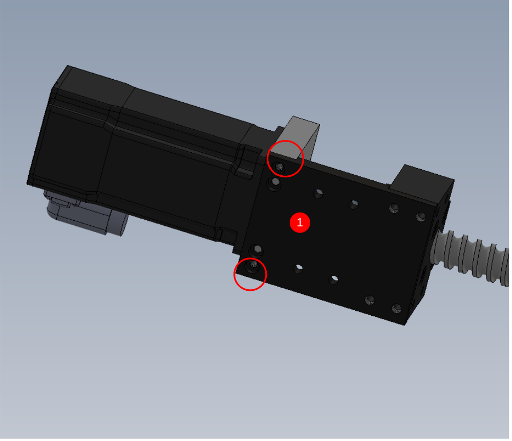
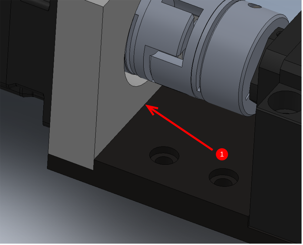
Étape 13 - combine servo assembly
1 Use M5 x 12 socket cap 2off to combine assemblies
Make sure faces are mated correctly (indicated) and coupling is aligned
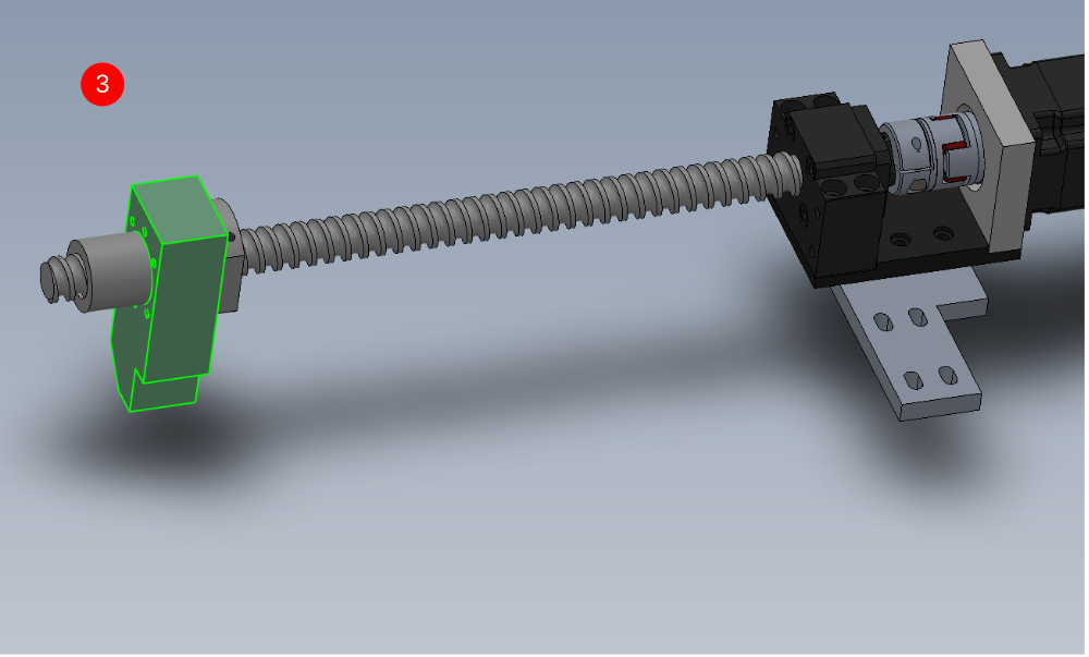
2 Fit D0015166 VY Motor Mounting Plate as shown using 4 off M6 x 16 sockets caps . Do not apply tension or adhesive to these bolts
3 Fit 90 degree grease nipple to leadscrew nut face in the direction shown. Fit D0015164 VY Leadscrew Block x 1 using 6 off M6 x 20 socket caps and A form washers .
Étape 14 - Assemble link bars

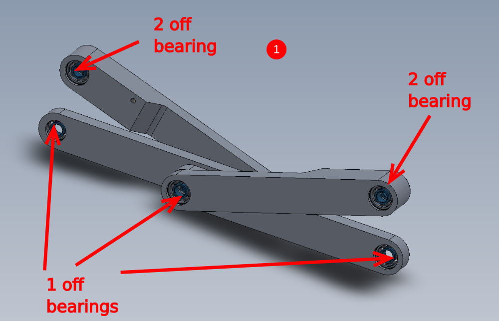
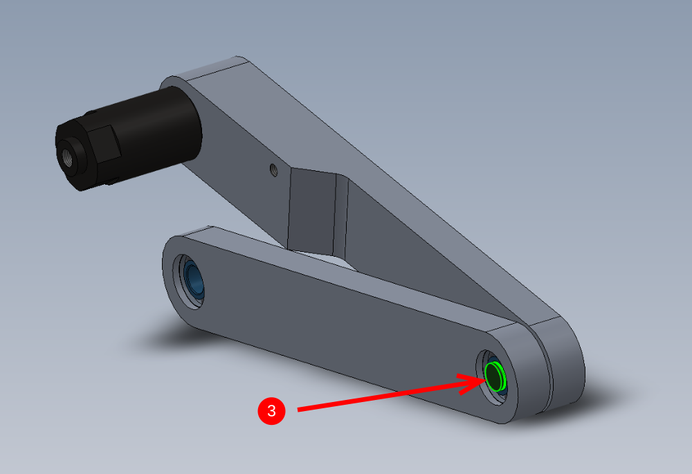
Étape 15 - Fit bearings
1 Fit B0001134 Ball Bearing 15ID 35OD 11 Long x 10 to parts
D0015260 Upper Link x 2
D0015261 Lower Link x 2
2 Captivate with 10 off 38mm internal circlip
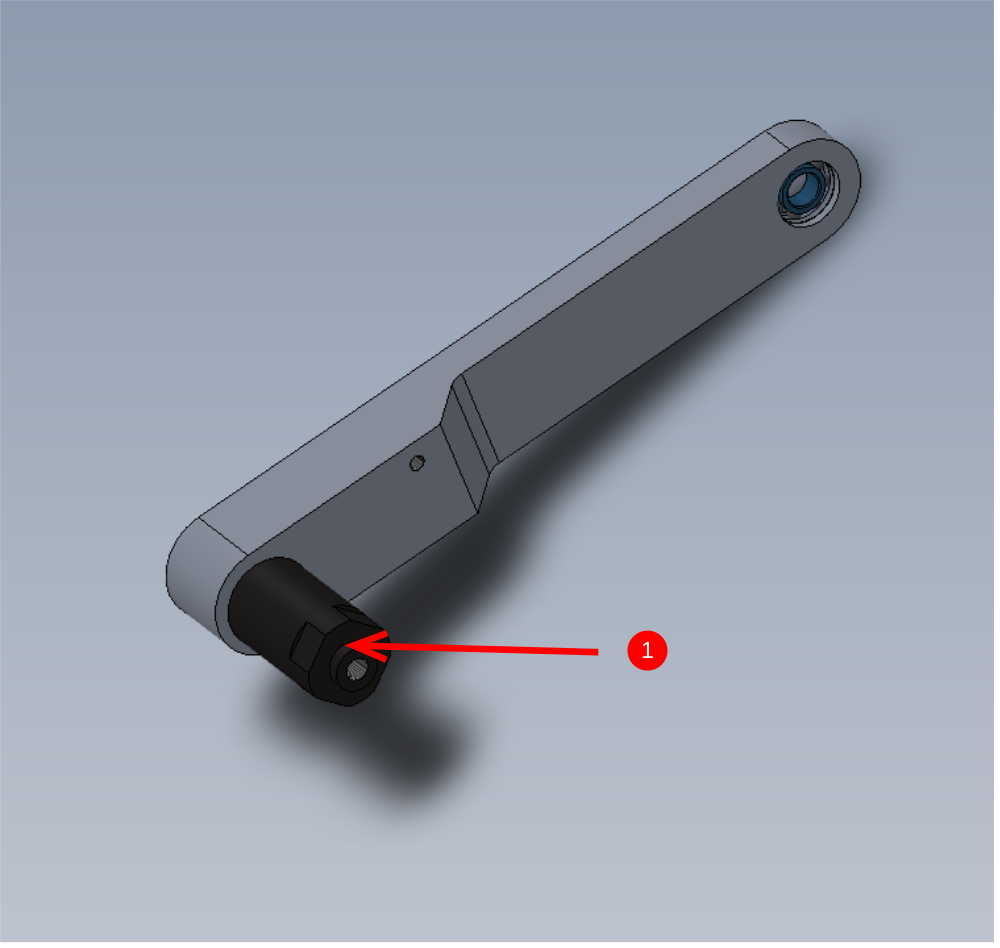
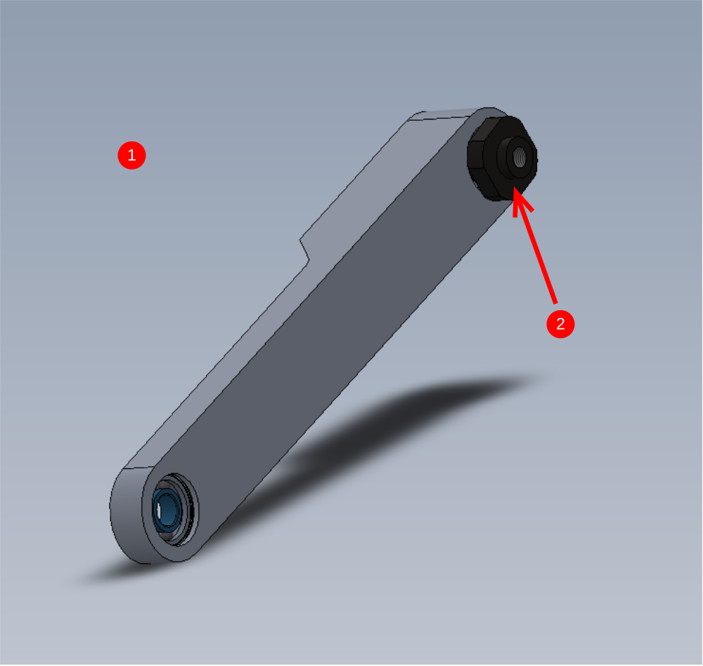
Étape 16 - Fit connector shafts
1 Fit D0015259 Upper Link Mount 2 x 1 as shown . Captivate with external circlip (size required)
2 Fit D0015258 Upper Link Mount 1 x 1 as shown. Captivate with external circlip 3 Fit D0015263 Mid Link Shaft as shown to combine parts built . Fix with 15mm external circlips
4 Fit D0015263 Mid Link Shaft as shown to combine parts built . Fix with external circlips (size required)
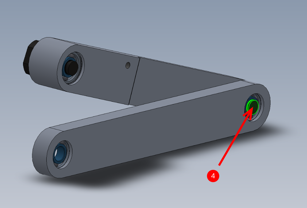
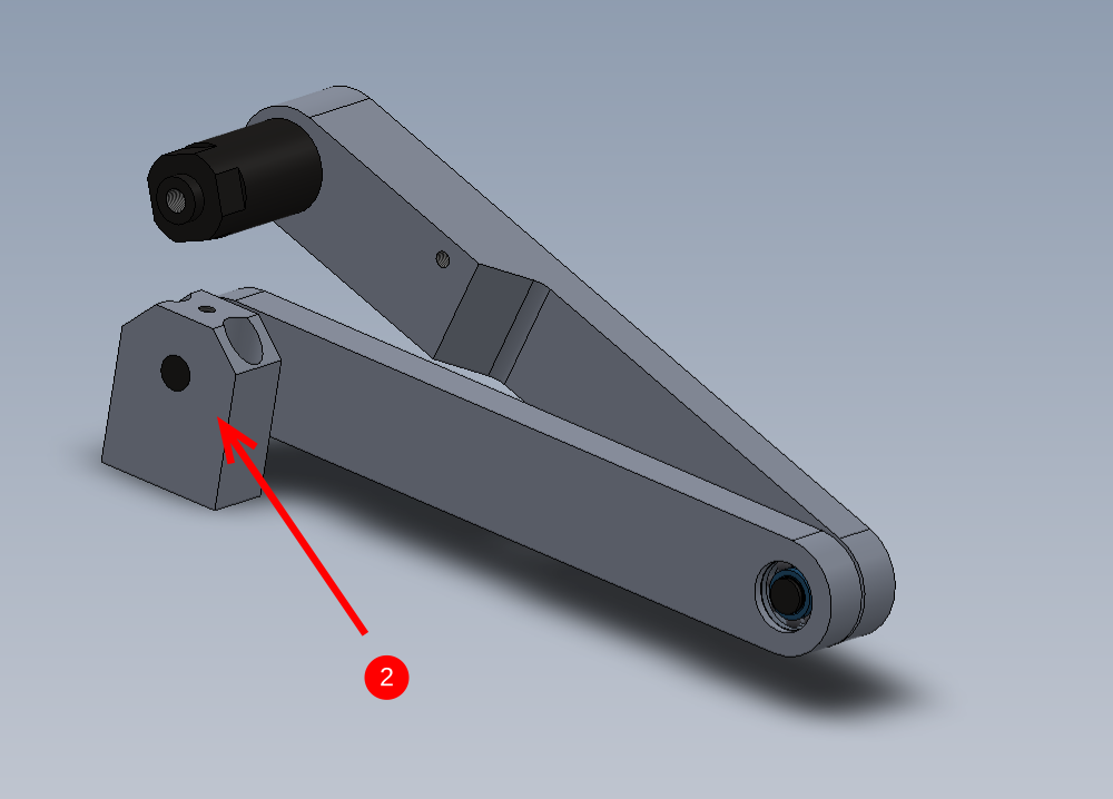
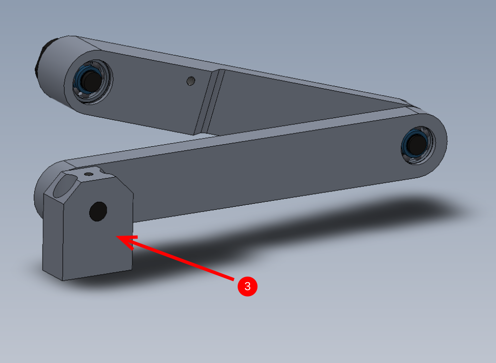
Étape 17 - Assemble link mounts
1 Fit D0015264 Lower Link Shaft to D0015262 Lower Link Mount as shown
Captivate with M8 x 16 KCP grubscrew aligned into dimple on shaft
2 off to assemble
2 Fit to assembly as shown and captivate with 38mm external circlip
3 Fit to assembly as shown and captivate with 38mm external circlip
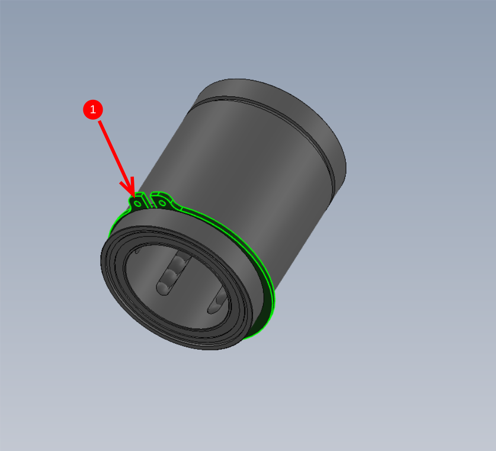
Étape 18 - Assemble bearing blocks
1 Fit 8 off B0001120 Circlip 62mm External to 8 off B0000109 Linear Bearing (IKO) 40 D x 62 D x 80 L x 8 as shown
2 Insert bearings into bores of parts
D0015152 V-Notch Upper Moving Bar x 1
D0015153 V-Notch Rear Moving Bar x 1
D0015154 V-Notch Front Moving Barx1
Bearing bore is slightly oversize, so bearings should push through by hand when aligned correctly
3 Fit 8 off circlips to captive fitted bearings
Étape 19 - Assemble Main Cross members
Use following parts
D0015147 V Notch Upper Support Bar x 1
D0015148 V Notch Lower Support Bar x 1
D0015149 VZ Shaft End Plate x 4
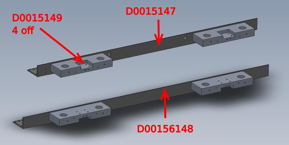
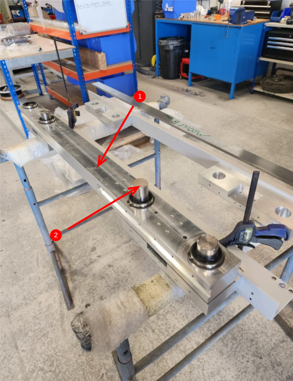
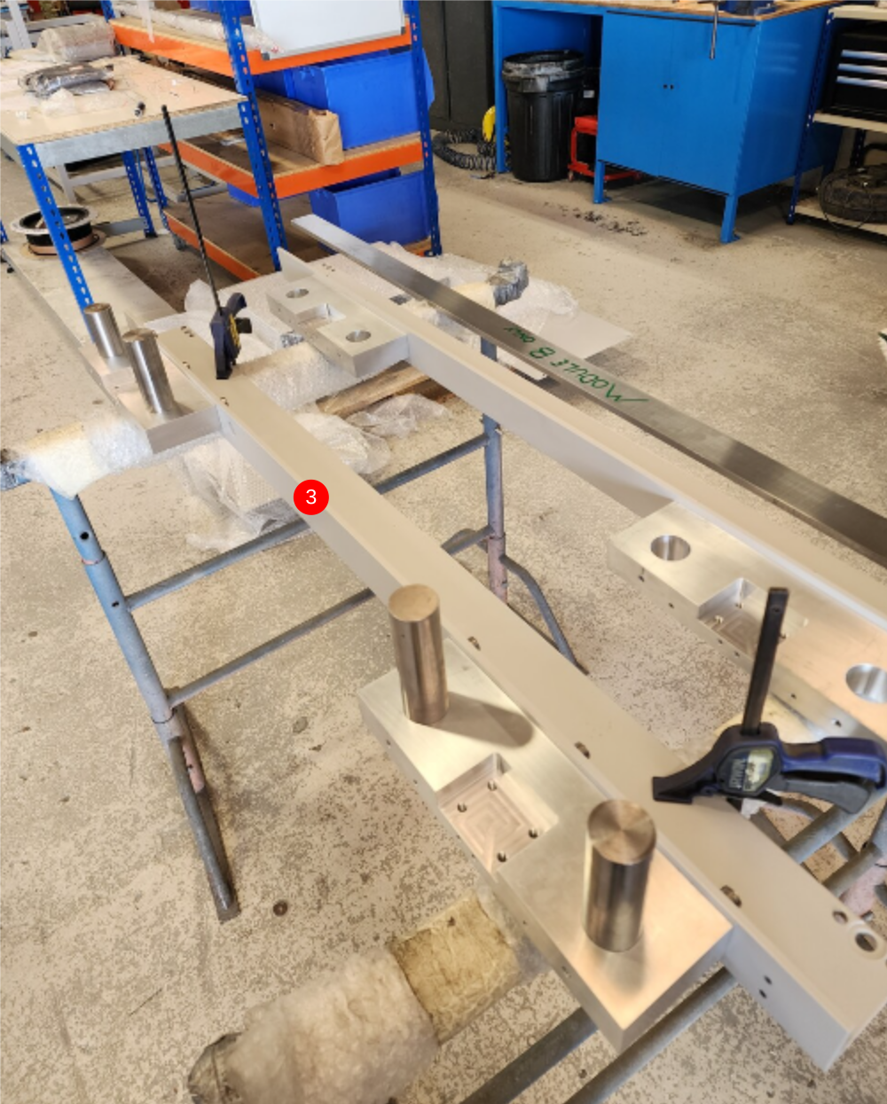
Étape 20 - Mount blocks and add setting jigs
Orientate D0015149 VZ Shaft End Plate x 2 as shown onto 0015147 V Notch Upper Support Bar
Use 12 of M10 x 25 socket caps and A form washers to lightly fasten blocks to support bar . Do not apply adhesive at this stage.


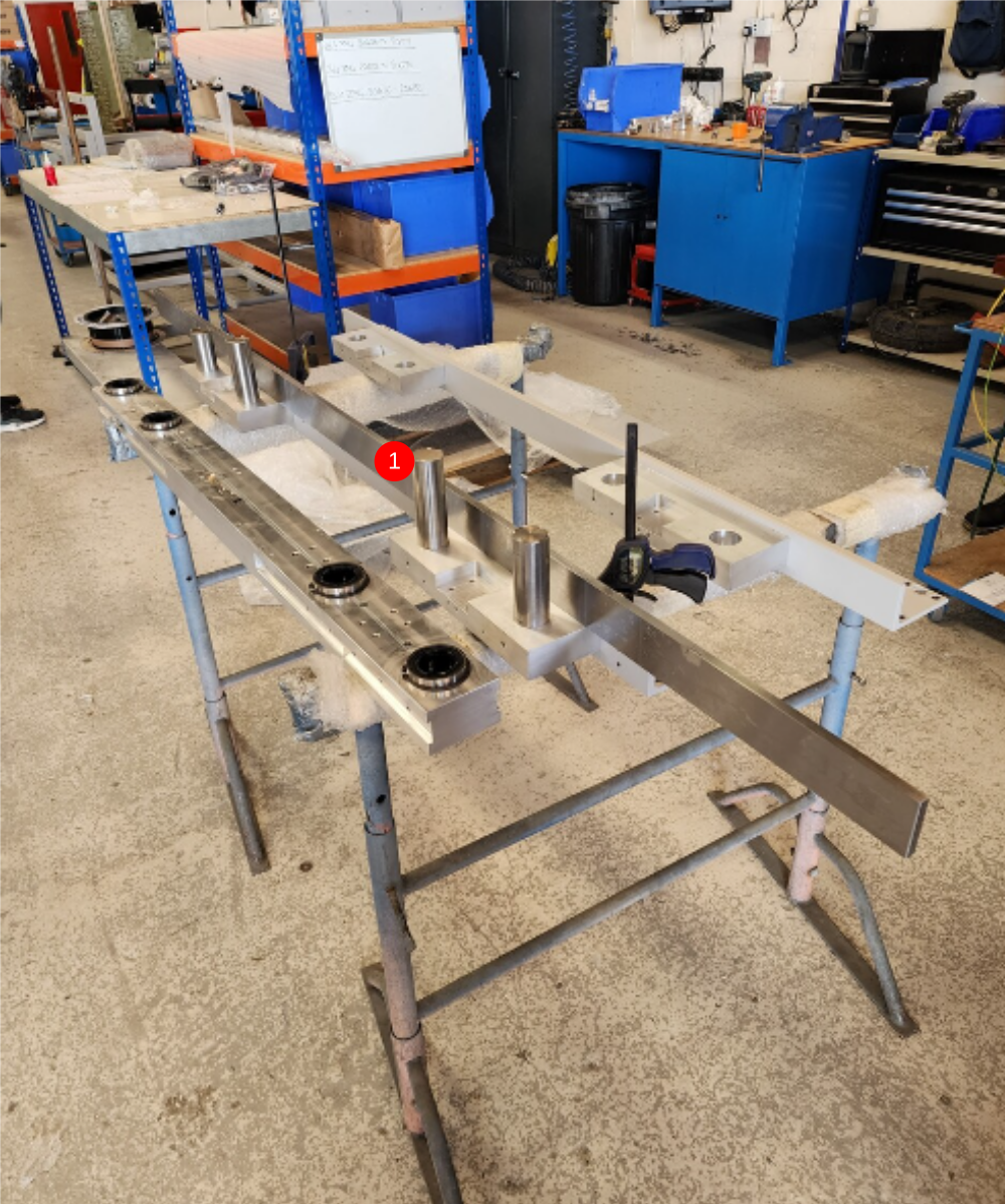
Étape 21 - Set pitching of blocks
1 Position pre assembles bearing block over end plates
2 Insert 4 off 40mm shaft blanks into bores through bearings in bearing block and secure with M8 x 12 flat bottomed grubscrews
3 Tighten m10 socket caps to hold pitching of end plates then remove bearing block

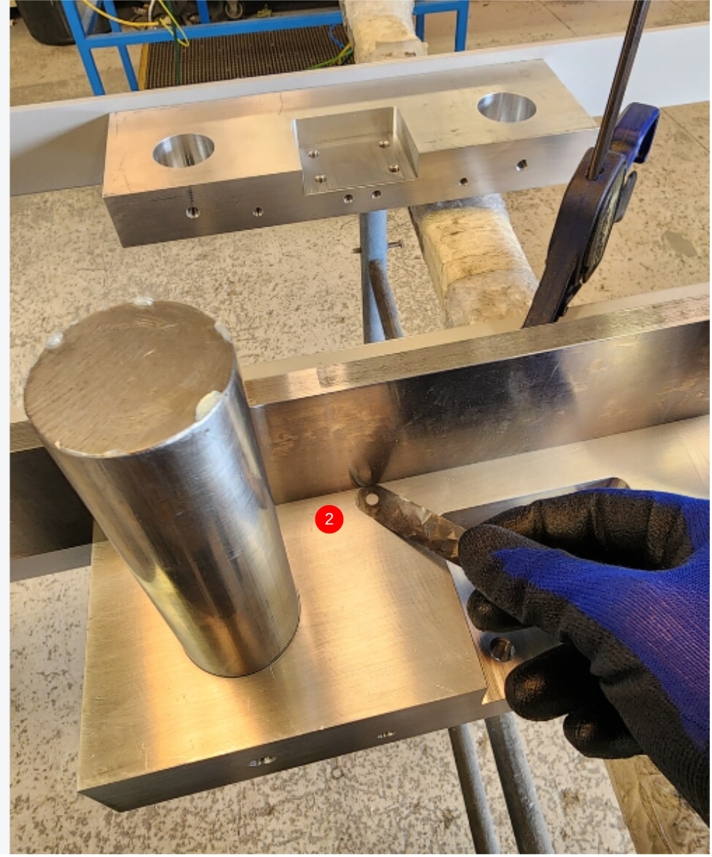
Étape 22 - Align with straight edge
1 Use 2 meter straight edge to flatness between blocks
2 Identify area where gap is present on each block using feeler gauge 0.05mm /0.002" to check
3 Only adjust 1 point on each block up to achieve flatness. Slacken socket caps on the end you want to adjust.
4 Tighten M10 Socket caps to fix position then recheck with straightedge
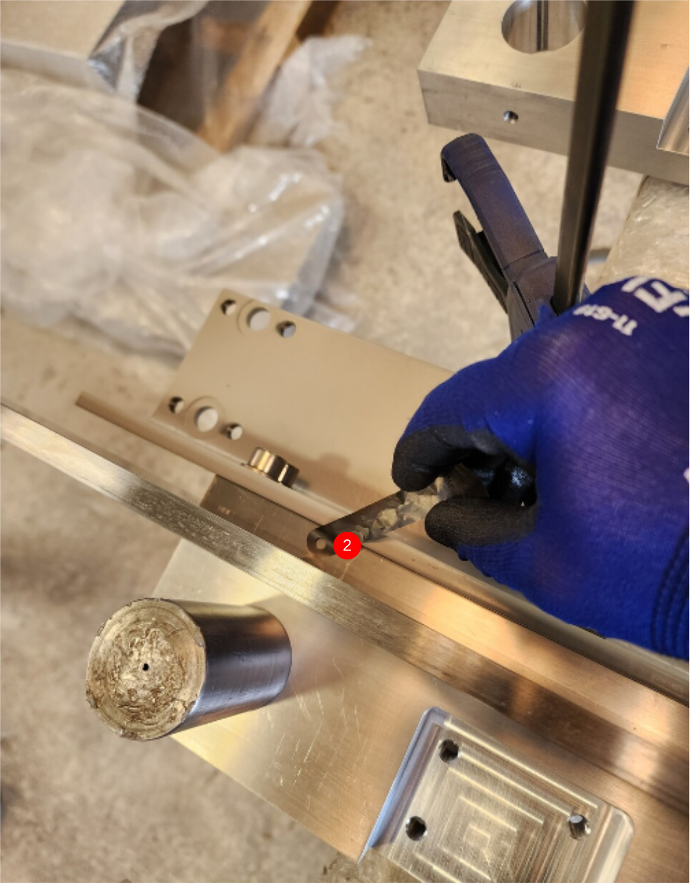
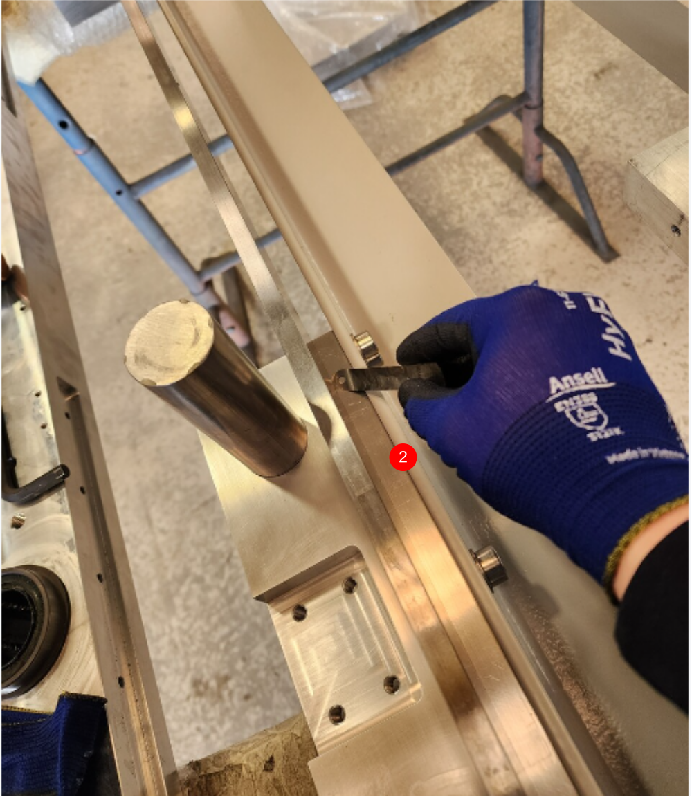
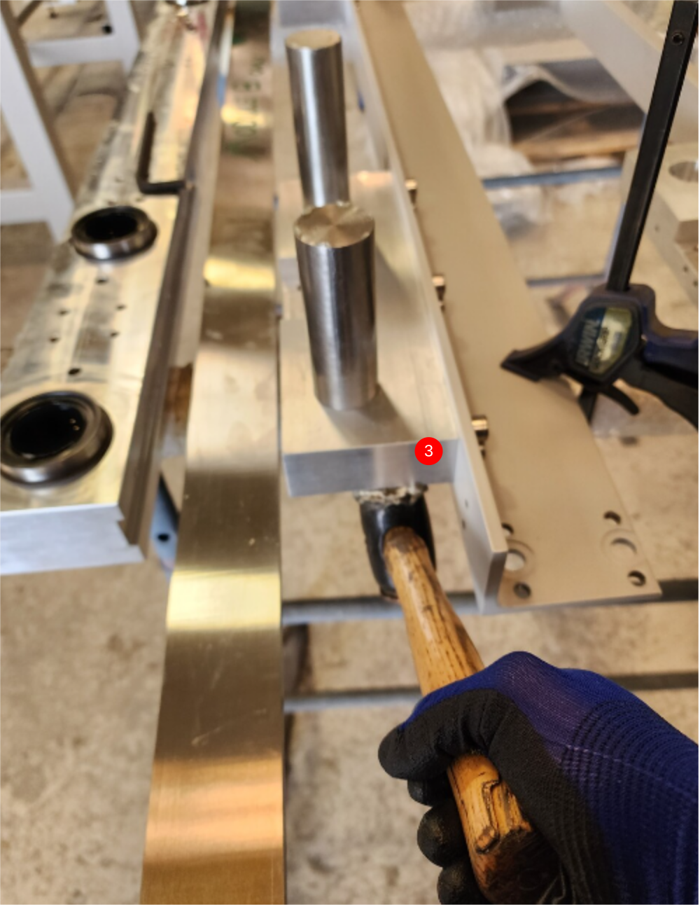
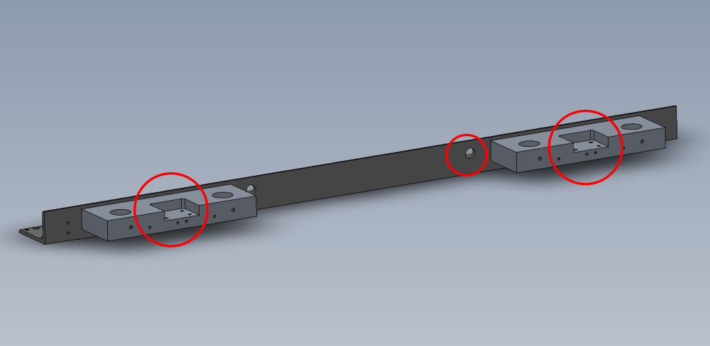
Étape 23 - Dowel
Position now requires doweling with 8mm x 50 dowels (2 per endplate )
Add dowels in the positions shown
Leave dowels protruding 10mm from painted face

Étape 24 - Finalise fixings
M10 socket caps can now be individually removed, adhesive added and re tightened and finalised
Étape 25 - Repeat steps 19 to 22
Use steps above to build 2nd crossmember using parts
D0015148 V Notch Lower Support Bar x 1
D0015149 VZ Shaft End Plate x 2
Note orientation of blocks


Draft
 Français
 English
 Deutsch
 Español
 Italiano
 Português