Installation steps for Electrical looms installation into Module B

Difficulté
Difficile
Durée
1 minute(s)
Sommaire
- 1 Introduction
- 2 Étape 1 - Unless otherwise stated
- 3 Étape 2 - Route Pre made 300hz connection
- 4 Étape 3 - Handing guide
- 5 Étape 4 - Guard switches
- 6 Étape 5 - Route Network cables
- 7 Étape 6 - Route 25way cable
- 8 Étape 7 - V notch Motor Cables and VY Datum
- 9 Étape 8 - Route V notch motor cables and X120 1st energy chain
- 10 Étape 9 - Route V notch motor cables, SY servo cable and X120 2nd energy chain
- 11 Étape 10 - Route V notch motor cables, SY servo cable and X120
- 12 Étape 11 - Door Hinge safety cables
- 13 Étape 12 - Camera Ring
- 14 Étape 13 - Camera Infeed
- 15 Étape 14 - Camera Outfeed
- 16 Étape 15 - Beacon and light
- 17 Étape 16 - Air service unit Connection
- 18 Étape 17 - Width Sensor connection
- 19 Étape 18 - Identify rear loom position
- 20 Étape 19 - Loom Cables
- 21 Commentaires
Introduction
Parts Required
Pre labelled Wiring loom assembly R0015034B from electrical team
Tools required
Flush cutters
Tie wraps small
Tie Wraps LargeÉtape 1 - Unless otherwise stated
All bolts to have Loctite 243 adhesive applied unless otherwise stated
All Threaded Pneumatic connections to have Loctite 570 applied
All bolts to be pen marked once adhesive applied and correct tension added

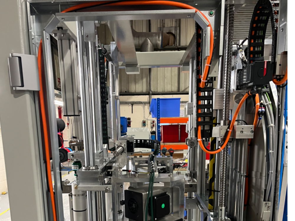
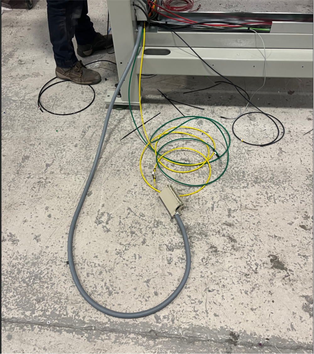
Étape 2 - Route Pre made 300hz connection
Route as shown power connection from wiring loom assembly
Z105 onwards as pictures
Z104 and below Different style plug mounted internally in trunking
Route cable to rear of machine as shown


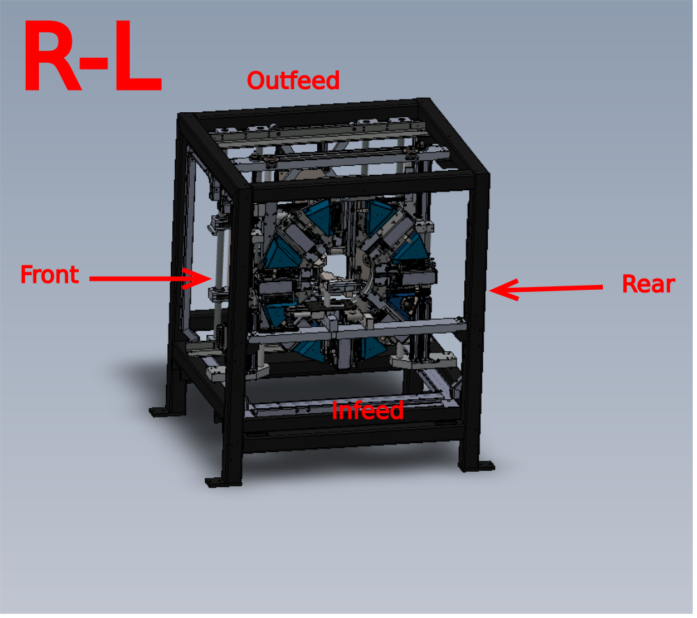
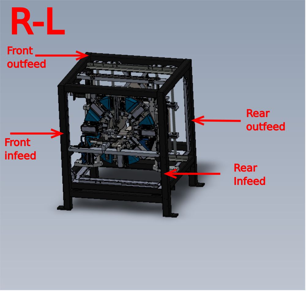
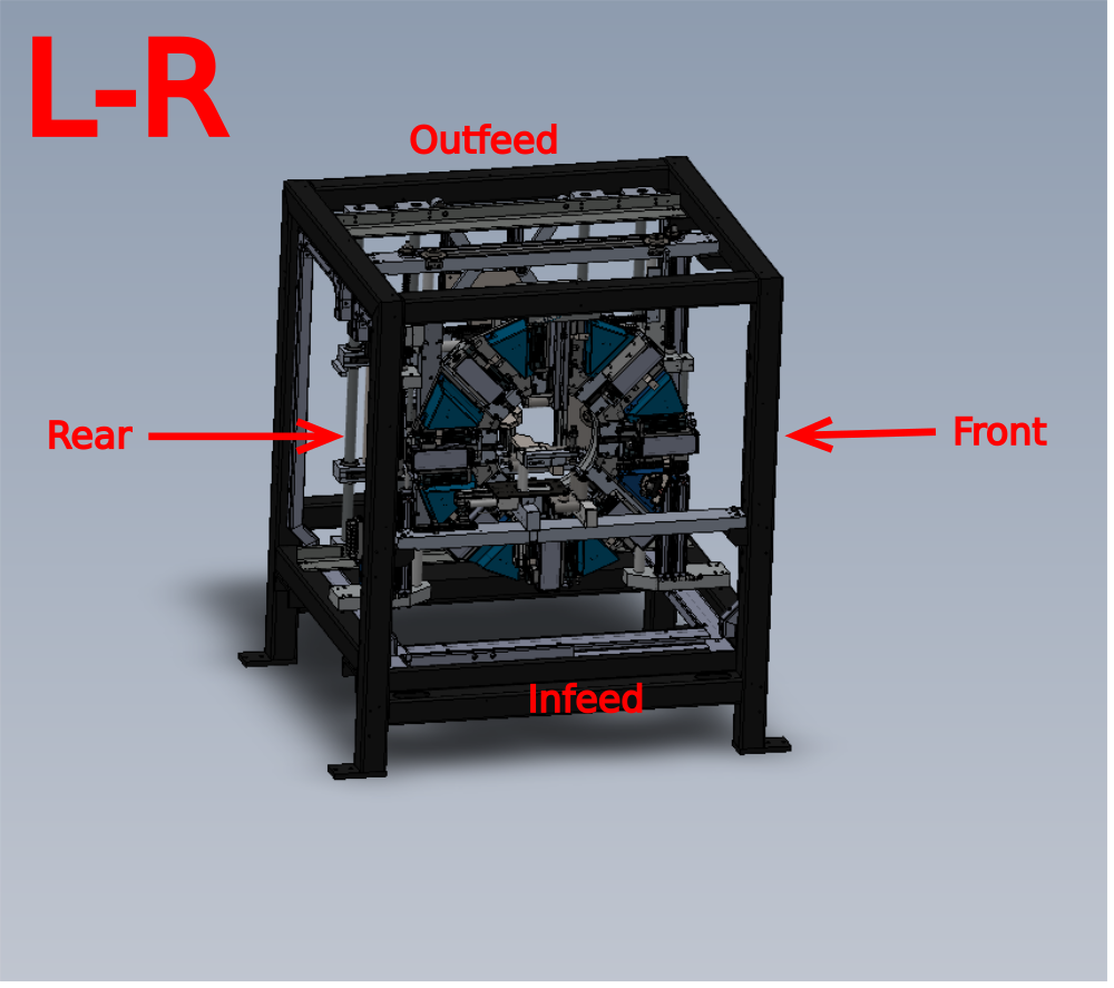
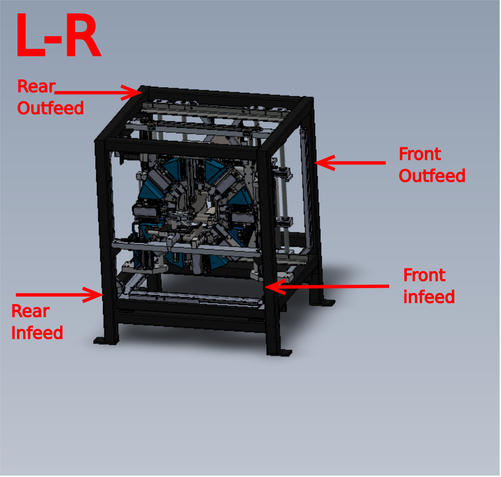
Étape 3 - Handing guide
Please diagram to determine handing positions of machine sections
Étape 4 - Guard switches
Use pre wired guard switches from wiring loom box
CB45B Front interlock guard switch
Cb46B Rear interlock guard switch
Use diagram to determine position
Run cable to rear exits of machine


Étape 5 - Route Network cables
Route yellow and green network cables from loom box as shown
Cables route from Rear outfeed to rear infeed as shown .
Please clarify length of cable to be left extended from front or back of machine please


Étape 6 - Route 25way cable
Route 25way cable as shown. Route from Rear Infeed to Rear outfeed positions
Male plug to be positioned at Rear infeed position as shown

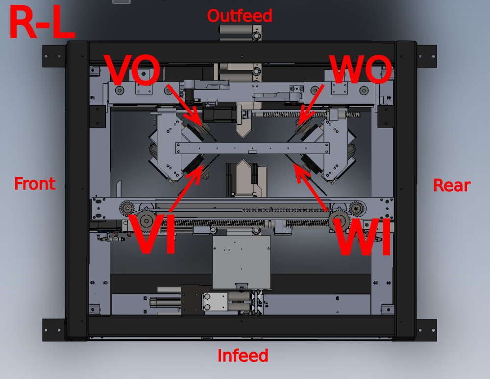
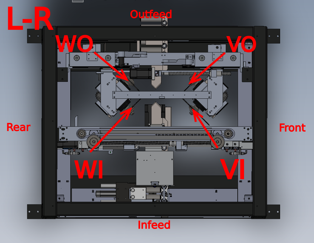
Étape 7 - V notch Motor Cables and VY Datum
Use cables
CB01B for connection to VI motor
CB02B for connection to VO motor
CB03B for connection to WI motor
CB04B for connection to WO motor
and already installed Cable x120
Motor identification should be determined by diagrams shown
Étape 8 - Route V notch motor cables and X120 1st energy chain
Route Cables as shown , to first energy chain , then through energy chain to exit point
Ensure cable retention points on energy chain brackets are used


Étape 9 - Route V notch motor cables, SY servo cable and X120 2nd energy chain
Use Servo cable identified V axis from wiring loom box, and incorporate with previous step cables to enter next energy chain .
Ensure cables are as shown and cable retention bracket is used to enable cables to be kept flat once fitted
Exit cables from top of energy chain


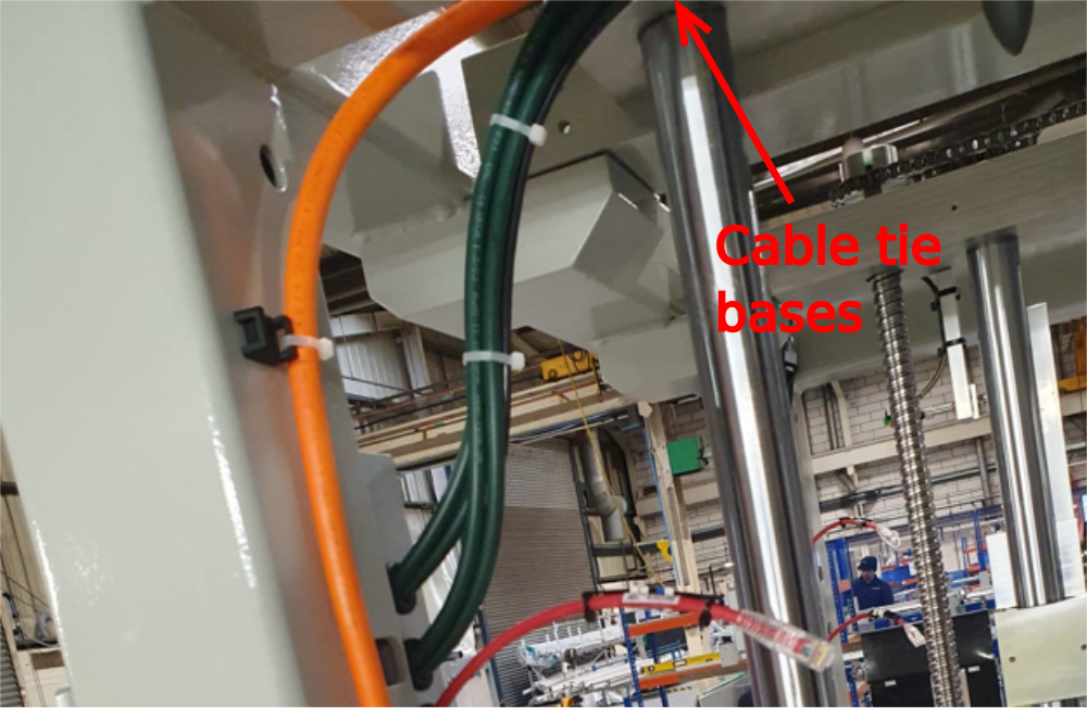
Étape 10 - Route V notch motor cables, SY servo cable and X120
Route 4 off green cables and x120 into trunking through 2 off 20mm grommit holes
Route servo cable as shown on cable tie bases
Ensure large cable base is fitted and used at indicated point
Exit cables at rear of machine


Étape 11 - Door Hinge safety cables
Use step 3 for correct identification of positions required
Use 4 off cables from wiring loom box
CB40B Front Infeed Hinge
CB41B Front Outfeed Hinge
CB42B Rear Infeed Hinge
CB43B Rear Outfeed Hinge
Ensure Tie base is used as shown , and star grommits are used for cable entry and exit through main frame work
All Cables to exit at rear of machine


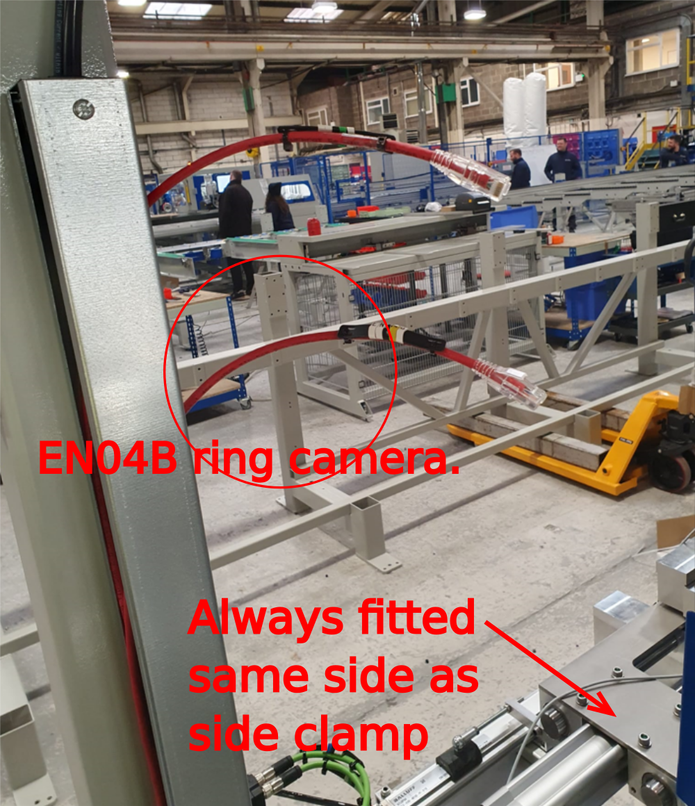
Étape 12 - Camera Ring
Use cable from loom box labelled EN04B
Run from vertical trunking and exit cable at rear of machine
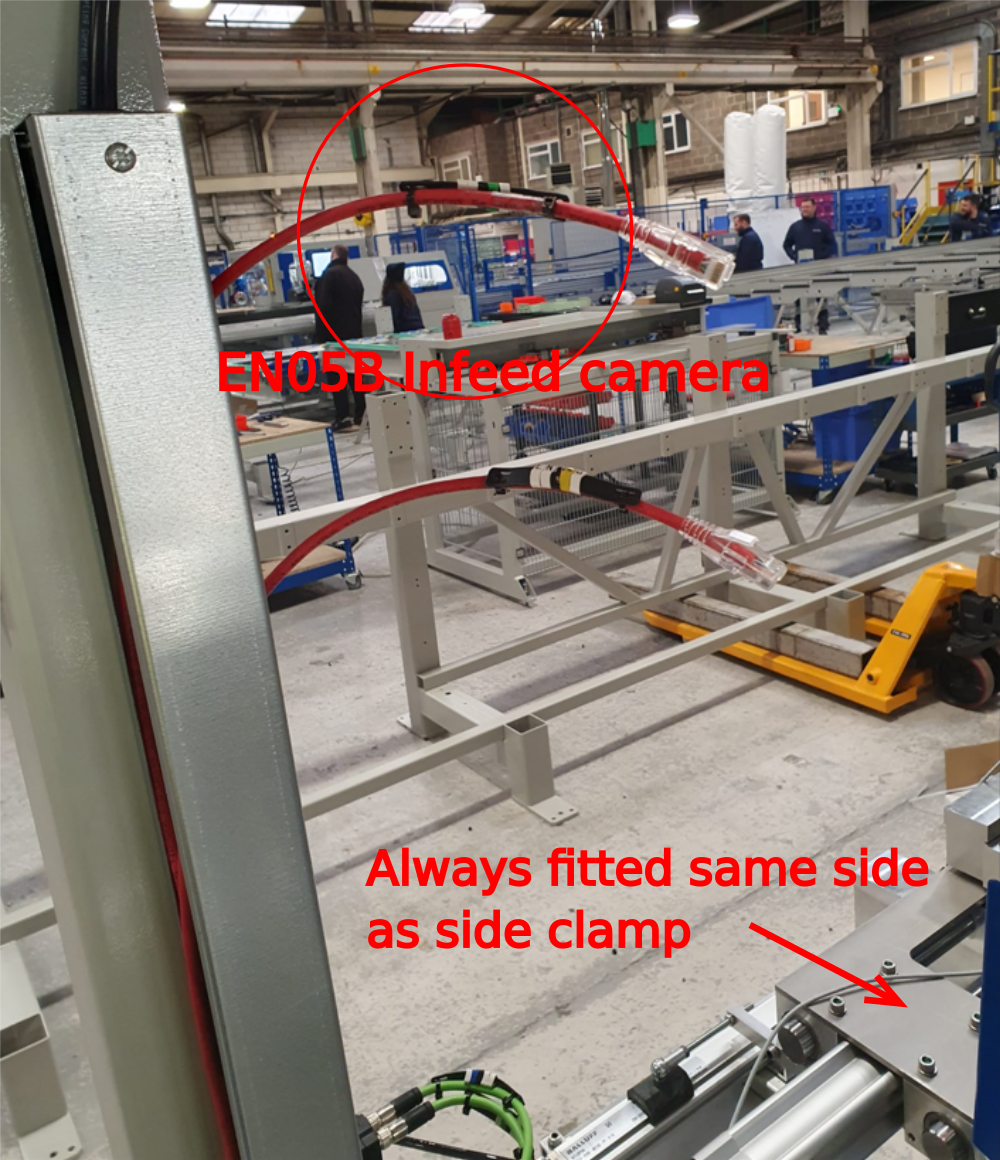
Étape 13 - Camera Infeed
Use cable from loom box labelled EN05B
Run from vertical trunking and exit cable at rear of machine
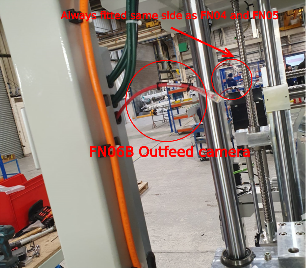
Étape 14 - Camera Outfeed
Use cable from loom box labelled EN06B
Always fitted same side of machine as previous 2 fitted camera cables
Run from vertical trunking and exit cable at rear of machine
Étape 15 - Beacon and light
Use cables CB532B and CB06B from wiring loom box.
Fit as shown to Infeed Front position on frame.
Route cables to exit at rear of frame

Étape 16 - Air service unit Connection
Use cable CB44B from wiring loom assembly.
Exit lower infeed trunking as shown leaving 1.5 meters out of trunking .
Route cable through trunking and exit at rear of frame

Étape 17 - Width Sensor connection
Use cable AX2 and connect to width sensor assembly as shown
For R-L configuration, cable must enter trunking and route across lower trunking from width sensor to FB03B connection box
For L-R configuration (shown) connect cable to width sensor assembly, enter trunking then exit again for connection to FB03B

Étape 18 - Identify rear loom position
Use diagram to identify rear loom routing point
For L-R cable loom should route to the right side (viewed from back )
For R-L cable loom should route to the left side (viewed from back )
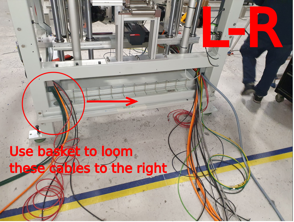
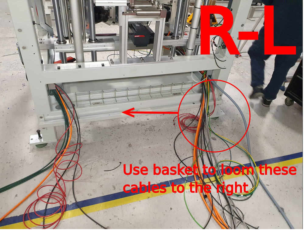
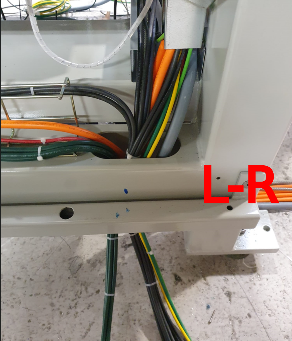
Étape 19 - Loom Cables
Loom cables across wire basket
Ensure top 2 fixing points are not used for cables (required for pneumatics)

Draft
 Français
 English
 Deutsch
 Español
 Italiano
 Português