Instructions to correctly align and mount hepco drive beam

Difficulté
Difficile
Durée
8 heure(s)
Introduction
Tools Required
Engineers level
Étape 1 - Unless otherwise stated
Always Use Loctite 243 on all fasteners
Always use Loctite 570 on all threaded pneumatic connections
Pen mark all fasteners to show finalised

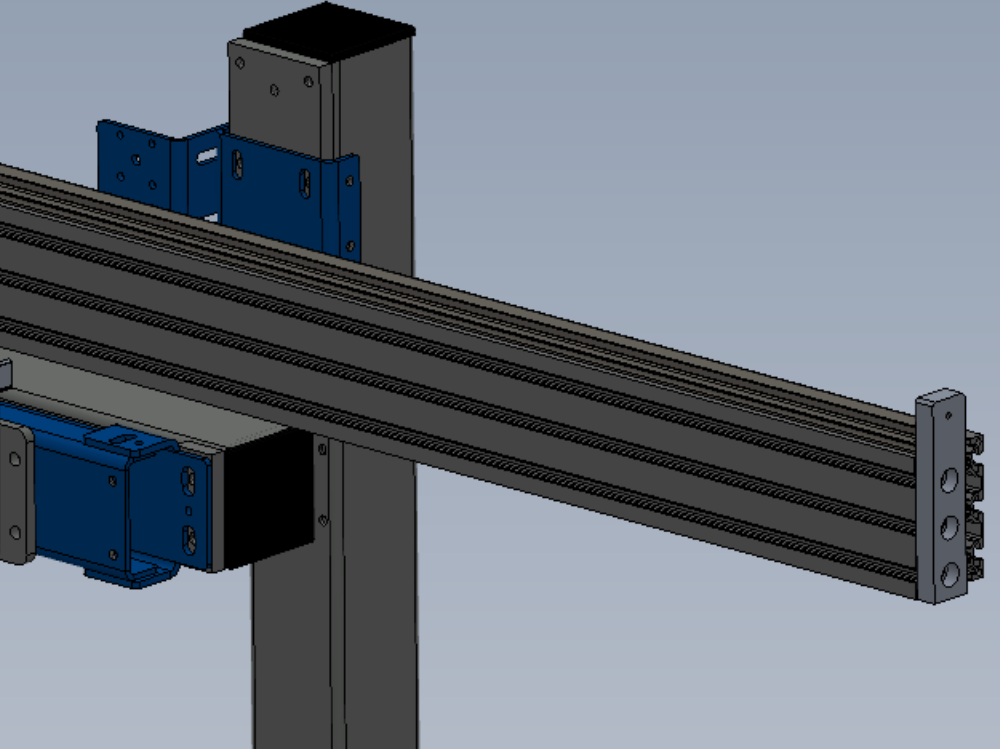
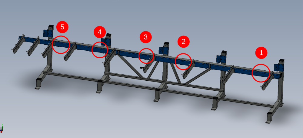
Étape 2 - Attach Setting jigs
Mount setting jigs to channel section in positions shown using M8 cap head bolts and heavy washers
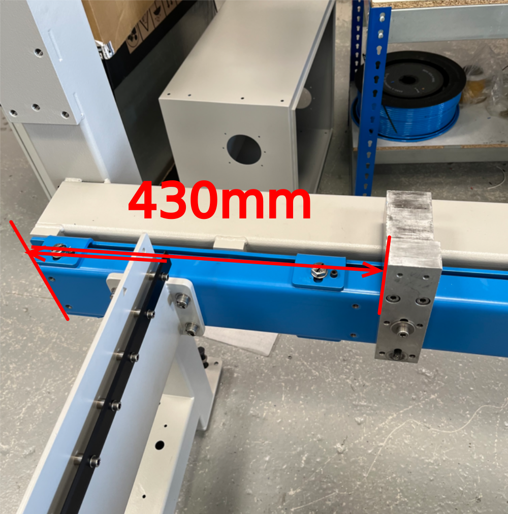
Position one shown will require fixing points drilling to channel section . Drill M8 and position to measurement shown of 430mm
Étape 3 - Level Setting Jigs
Use an engineers level to individually adjust each jig to be level on both axis


Étape 4 - Level x axis between jigs
Using a 2 meter straight edge , the jigs should be levelled to each other as shown


Étape 5 -
Étape 6 -
Étape 7 -
Étape 8 -
Étape 9 -
Étape 10 -
Draft
 Français
 English
 Deutsch
 Español
 Italiano
 Português