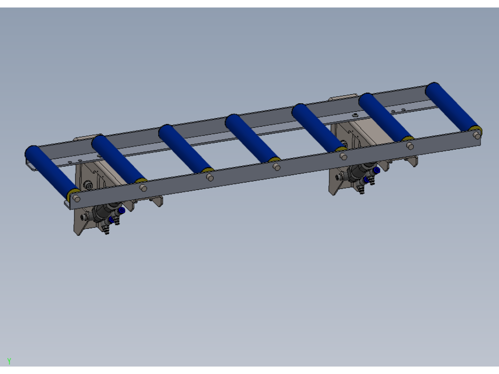
Instructions to bench assemble roller beds

Difficulté
Moyen
Durée
6 heure(s)
Sommaire
- 1 Introduction
- 2 Étape 1 - Unless otherwise stated
- 3 Étape 2 - Assemble Cylinder assembly
- 4 Étape 3 - Check for rework
- 5 Étape 4 - Check for rework of following parts
- 6 Étape 5 - Fit bushes and mount cylinder
- 7 Étape 6 - Combine support arm and roller bracket
- 8 Étape 7 - Prepare M3 holes
- 9 Étape 8 - Assemble Large roller Table
- 10 Étape 9 - Fit rollers
- 11 Étape 10 - Assemble medium roller table
- 12 Étape 11 - Assemble small roller table
- 13 Étape 12 - Pneumatic pre assembly
- 14 Commentaires
Introduction
Tools Required
Standard Hex key set
Standard spanner set
Tape measure/Rule
8.2mm HSS drill
Drill
Parts Required
B0001092 Plastic Roller Blue Ø30 x 194 Long. Spring Loaded Shafts x 45
B0001103 bush flange x 26
B0001220 spacer x 26
D0015001 Roller Bed Cylinder Arm x 13
D0015002 Shaft 10mm: 58mm Rod End x 13
D0015003 Roller Bed Rail 375mm x 4
D0015004 Roller Bed Rail 550mm x 2
D0015005 Roller Bed Rail 1000mm x 10
D0015006B Roller Bed Arm Bracket x 13
D0015010 Rod End Spacer x 26
D0015481 Shaft 8mm: 50mm Cylinder Pivot x 13
D0015547 Sensor Blower Plate x 2
D0015603 Roller Bed Pivot Shaft (silver steel) x 13
E0001120 Sensor: Ultrasonic M8 20-150mm x 2
P0000046 Fitting: 'Y' Adaptor 6mm x 1
P0000049 Cylinder Spherical Bearing M10 x 1.25 x 13
P0000200 Elbow Adaptor 6mm - M5 x 2
P0001030 Fitting: SMC 6mm Equal Tee x 10
P0001110 cylinder 25 x 10 x 13
P0001198 Fitting flow reg x 26
Étape 1 - Unless otherwise stated
Use locktite 243 on all fasteners
Use loctite 572 on all threaded pneumatic connection
Pen mark all fasteners to show finalised

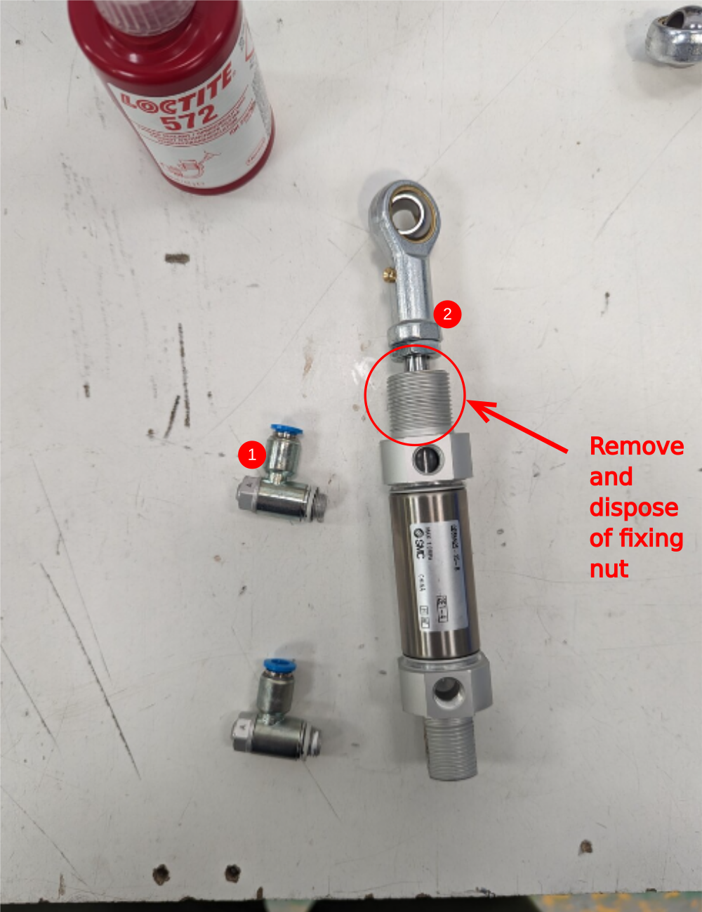
Étape 2 - Assemble Cylinder assembly
13 off
1 Fit 2 off P0001198 fittings to cylinder P0001110
2 Fit spherical bearing P0000049 to cylinder end , Do not add final tension to the nut

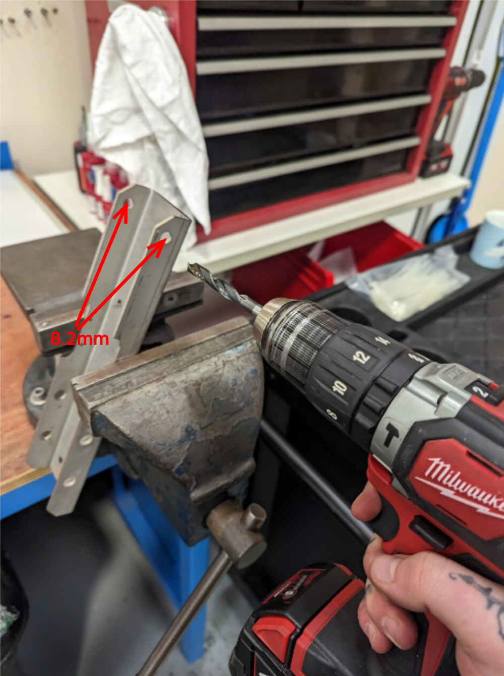
Étape 3 - Check for rework
13 off
Check part D00150001 has been supplied to new specification
Check indicated hole, should measure 8.2mm. If not open up with hand drill
Drawing change requested 06/06/23 to amend from 8mm to 8.2mm
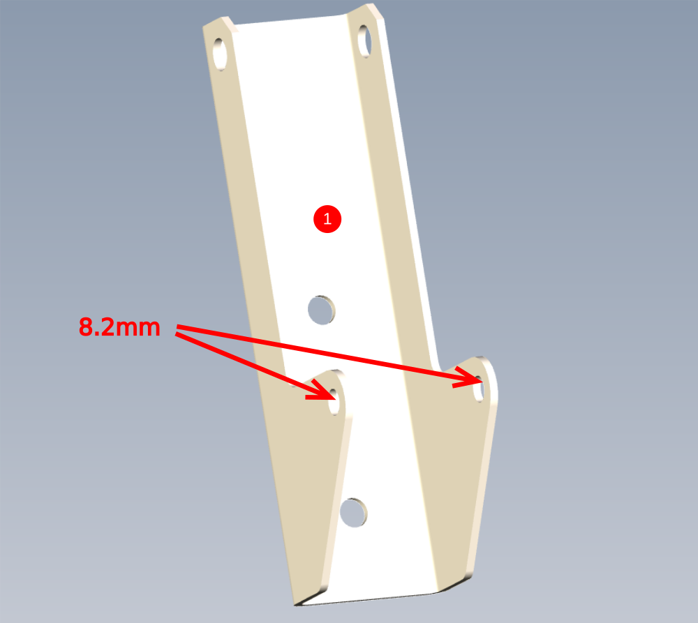
Étape 4 - Check for rework of following parts
1 D0015006B indicated holes should measure as shown. Rework by hand if issued old spec
ECR raised 06/06/23
2 D0015002 rod end shaft . Check fit in P0000049 spherical bearing . Polish down diameter to allow shaft to pass through.
ECR raised 06/06.23 to improve tolerance of shaft to allow better fitment
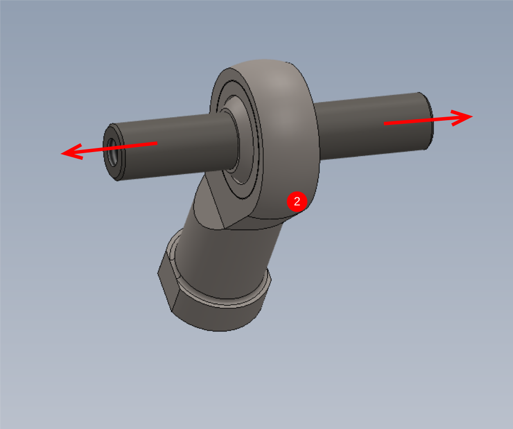
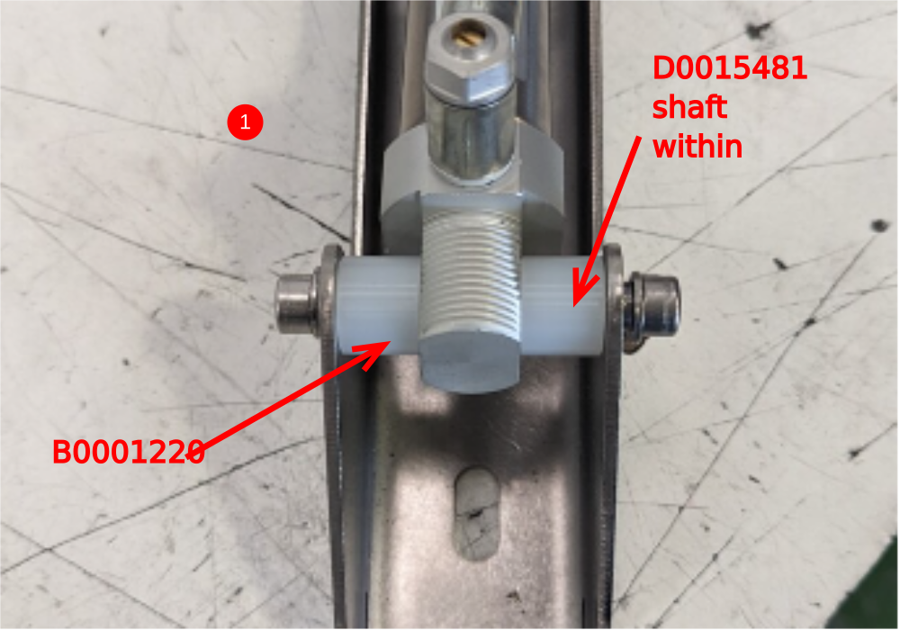
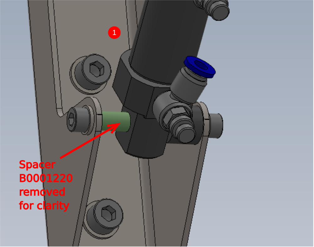
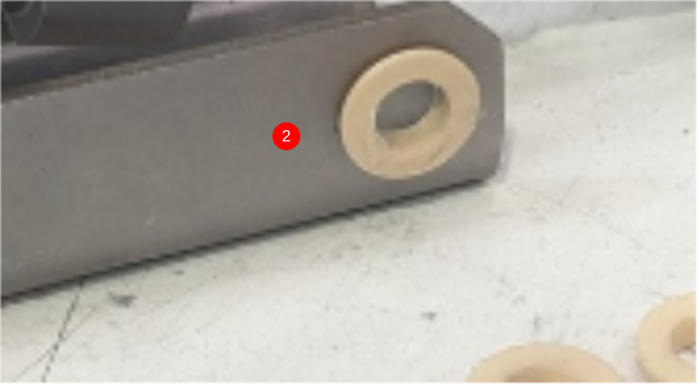
Étape 5 - Fit bushes and mount cylinder
13 off
1 Combine D0015481 shaft and B0001220 spacer as shown to mount cylinder to bracket. Use 26 off M6 x 12 socket caps and A form washers to fasten
2 Fit 2 off B0001103 bushes to D0015006B

Étape 6 - Combine support arm and roller bracket
13 off
1 Fit 2 off D0015010 spacers, 1 off d0015002 shaft through spherical bearing and fix with 2 off m6 X 12 socket caps and A form washers
2 Fit 1 0ff D0015603 pivot shaft with 2 off M6 x 12 socket caps and A Form washers
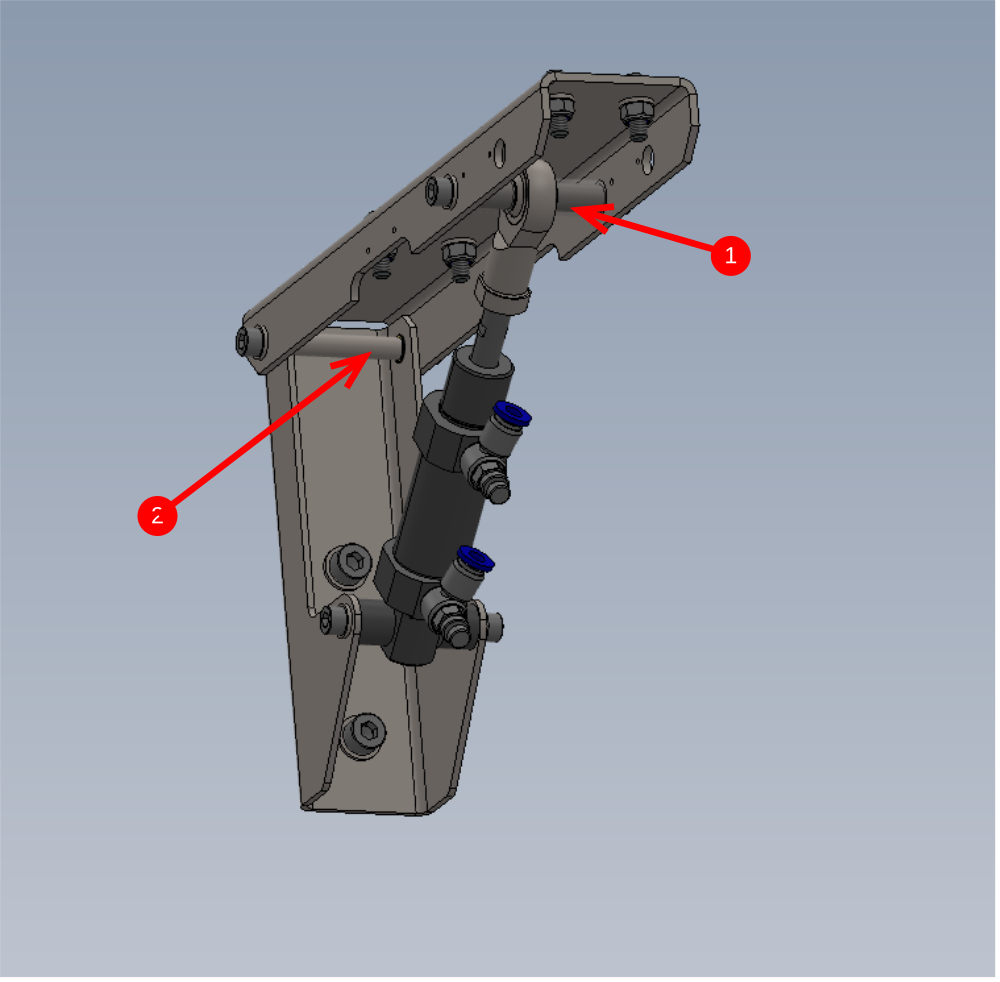
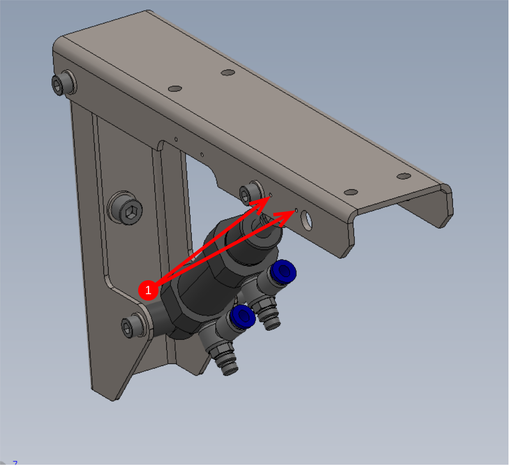
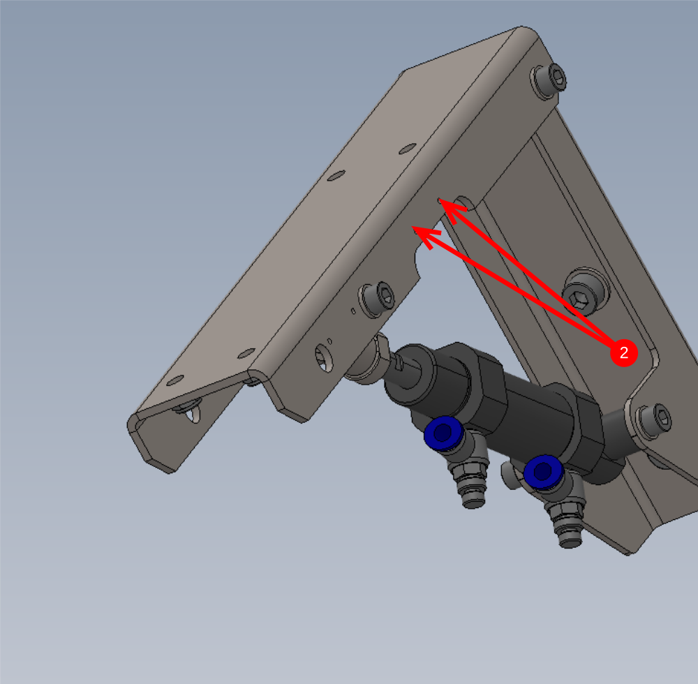
Étape 7 - Prepare M3 holes
1 off only and mark for later Reference
1 Tap 2 off indicated holes M3
2 Tap 2 off indicated holes M3
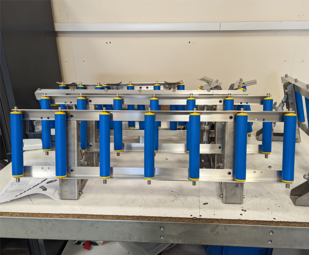
Étape 8 - Assemble Large roller Table
5 off to be assembled
1 Mount 2 off D0015005 to prebuild cylinder assemblies as shown
Use M6 x 20 button socket head , A form washer and M6 nyloc nuts to fix.
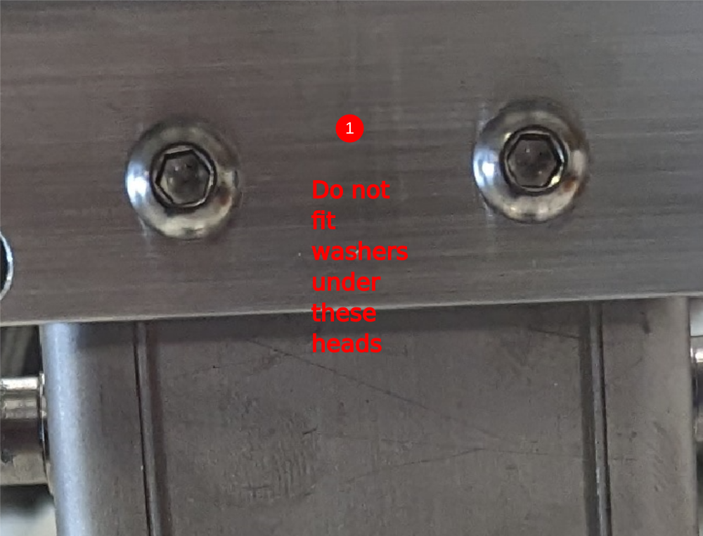
Do not use washer under head of button head screw, only use washers on nut side
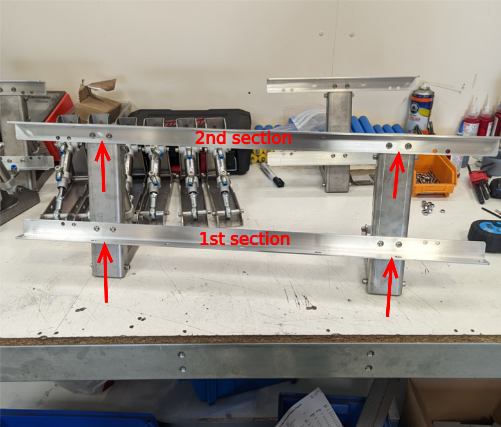
2 Adjust the 2 off D0015005
1st section pushed against edge of clearance hole in direction shown
2nd section pushed in same direction
3rd Check parallel and adjust to correct
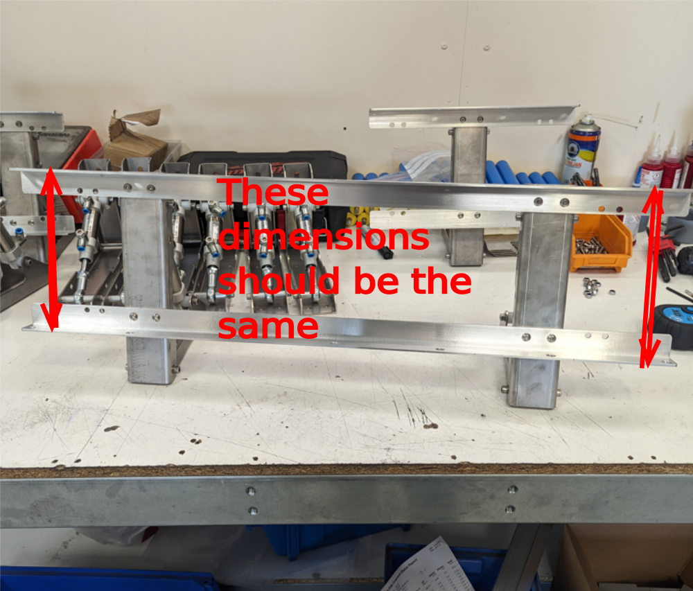
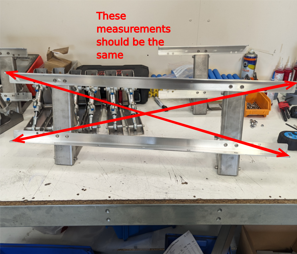
4th check squareness by taking corner measurements and adjusting if required
Once all above is achieved, finalise fasteners
Étape 9 - Fit rollers
Fit 7 off B0001092 roller to each assembly
Étape 10 - Assemble medium roller table
Using same checks and setting as above assemble roller table with 4 rollers as shown

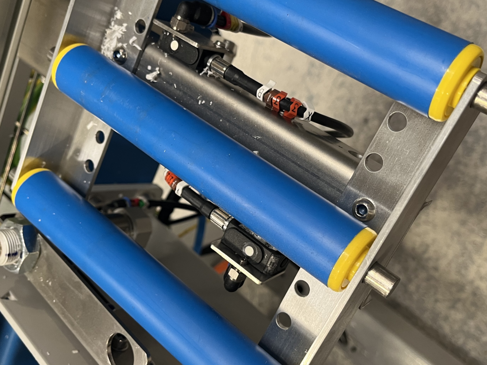
Étape 11 - Assemble small roller table
2 off
Using same checks and setting as above assemble 2 off roller tables with 3 rollers as shown,
Use the pre built cylinder bracket with m3 tapped holes for 1 off, and add 2 off Sensor E001120 ,2 off Blower P0000200 and 2 off bracket D0015547 as shown . Connect P0000160 flow reg with a small section of 6mm black air pipe to each P0000200 elbow. Label as 2449


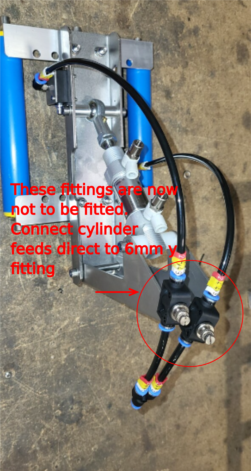
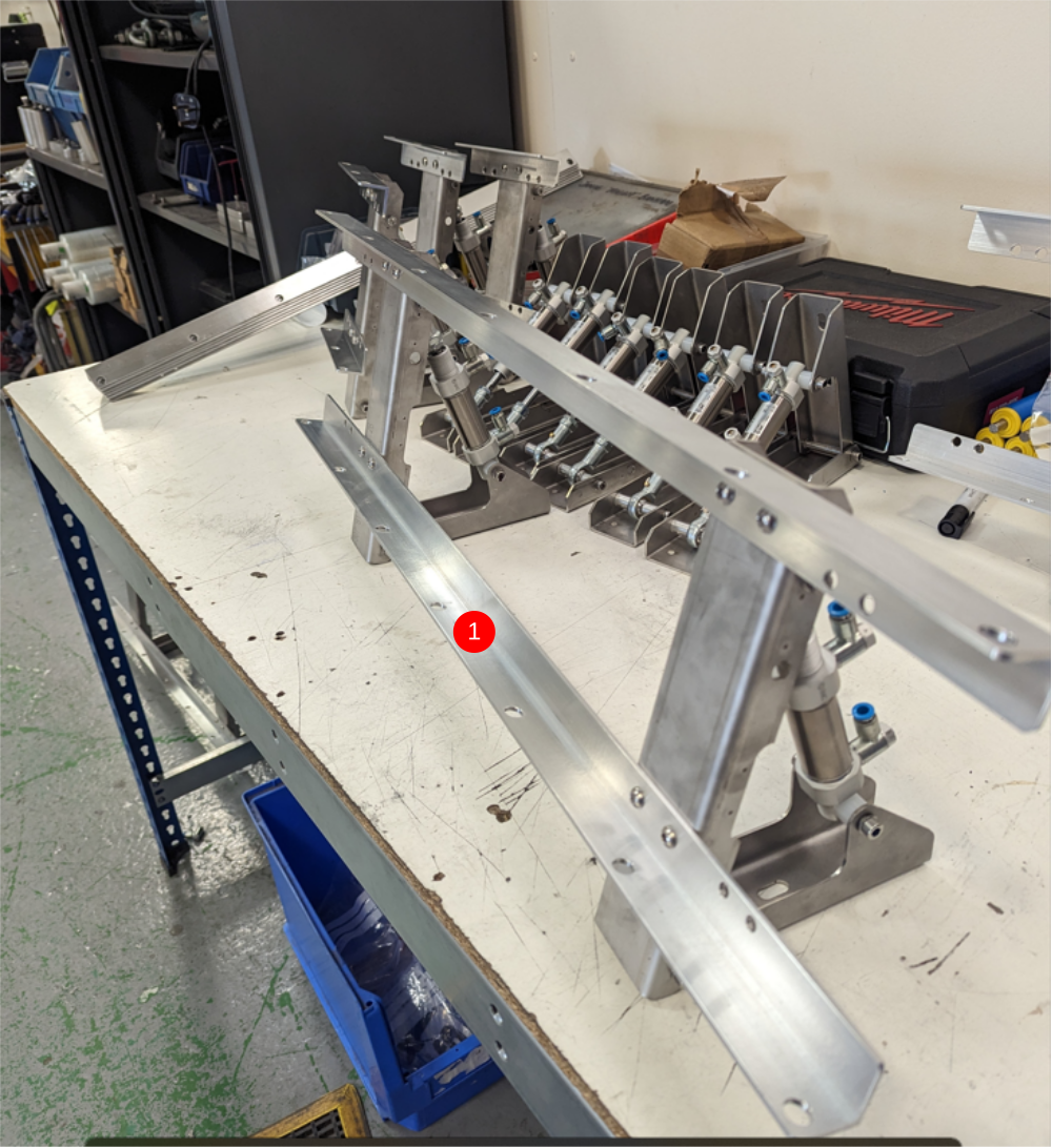
Étape 12 - Pneumatic pre assembly
5 off
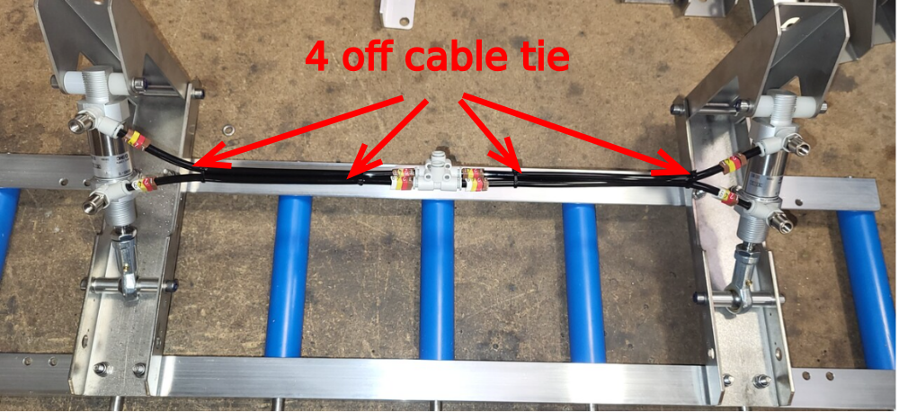
7 Roller bed assemblies with two cylinders require pneumatic pipe installation.
Use identification numbers as follows
1241 Home position
1249 Active position (down)
Draft
 Français
 English
 Deutsch
 Español
 Italiano
 Português